List of Figures
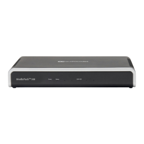
Figure 3-1: Front Panel..........................................................................................................................13
Figure 3-2: Rear Panel ..........................................................................................................................15
Figure 4-1: Minimum Vertical Space for 19-inch Rack Mounting..........................................................17
Figure 4-2: Positioning Shelf in Rack.....................................................................................................18
Figure 4-3: Positioning the Device's Anti-Slide Rubber Legs into Shelf's Openings.............................19
Figure 4-4: Device Mounted on Shelf in 19-inch Rack..........................................................................19
Figure 4-5: Dimensions for Drilled Holes...............................................................................................20
Figure 4-6: Protruded Screw Distance from Wall Surface.....................................................................22
Figure 4-7: Hanging Device on Screw Heads .......................................................................................22
Figure 5-1: Default Ethernet Port Groups and Port String Names for Software Configuration.............23
Figure 5-2: Cabling LAN Ports...............................................................................................................24
Figure 5-3: RJ-45 Connector Pinouts for TE or NT BRI Ports...............................................................25
Figure 5-4: Cabling BRI Ports................................................................................................................26
Figure 5-5: Cabling BRI PSTN Fallback................................................................................................27
Figure 5-6: RJ-11 Connector Pinouts for FXS Interface........................................................................28
Figure 5-7: Connecting FXS Interfaces .................................................................................................29
Figure 5-8: RJ-11 Connector Pinouts for FXO Interface .......................................................................30
Figure 5-9: Connecting FXO Interfaces.................................................................................................30
Figure 5-10: RJ-11 Connector Pinouts for FXS Lifeline ........................................................................31
Figure 5-11: Cabling the FXS Analog Lifeline .......................................................................................31
Figure 5-12: RJ-45 to DB-9 Female Cable Adapter ..............................................................................32
Figure 5-13: Cabling Serial Port ............................................................................................................32
Figure 5-14: Connecting USB Storage Device......................................................................................33
Figure 5-15: AC/DC Power Adapter ......................................................................................................34
Figure 5-16: Inserting Plug into Power Adapter.....................................................................................35
Figure 5-17: Cabling to Power using Power Adapter............................................................................36
List of Tables
Table 3-1: Physical Dimensions and Operating Environment...............................................................13
Table 3-2: Front Panel Description........................................................................................................13
Table 3-3: Power LED Description ........................................................................................................14
Table 3-4: Status LED Description ........................................................................................................14
Table 3-5: Front Panel Description........................................................................................................15
Table 3-6: LAN LED Description............................................................................................................16
Table 5-1: RJ-45 Connector Pinouts for GE..........................................................................................23
Table 5-2: RJ-45 to DB-9 Serial Cable Connector Pinouts ...................................................................32
Table 5-3: Power Specifications............................................................................................................34
Table 5-4: Power Adapter with Interchangeable Plugs.........................................................................35


