manuals.online logo
Brands
  1. Home
  2. •
  3. Brands
  4. •
  5. Audiovox
  6. •
  7. Car Video System
  8. •
  9. Audiovox VOD10 - Car - Overhead LCD Monitor User manual

Audiovox VOD10 - Car - Overhead LCD Monitor User manual

Installation Guide
VOD10
10.2” OVERHEAD LCD MONITOR
WITH DVD PLAYER
R
Important Notice
An LCD panel and/or video monitor may be installed in a motor vehicle and visible to the
driver if the LCD panel or video monitor is used for vehicle information, system control,
rear or side observation or navigation. If the LCD panel or video monitor is used for
television reception, video or DVD play, the LCD panel or video monitor must be installed
,
so that these features will only function when the vehicle is in "park" or when the vehicle s
parking brake is applied.
An LCD panel or video monitor used for television reception, video or DVD play that
operates when the vehicle is in gear or when the parking brake is not applied must be
,
installed to the rear of the driver s seat where it will not be visible, directly or indirectly, to
the operator of the motor vehicle.
Installation of overhead products requires careful planning and preparation. Be
extremely careful when working on a vehicle with side curtain air bags. Do not route
wires near any portion of the side curtain air bag assemblies. This includes any anchor
points in A, B, C or D pillars of the vehicle. Routing wires in these areas or running wires
by the side curtain air bags can prevent the side curtain air bag from fully deploying which
can result in personal injury to vehicle occupants. If you have any questions regarding
wire routing in a vehicle, please contact Audiovox Technical Support at 1-800-225-6074.
When connecting power and ground in a mobile video installation ensure that the ACC
wire is fused at the point where it is connected to the vehicle ACC wiring. Failure to do
so can result in damage to the vehicle if a short circuit develops between the vehicle
connection point and the mobile video product.
Important Note
The VOD10 incorporates two new features:
1) A wireless FM Modulator
2) Snap on Covers with matching Trim Rings (Shale and Pewter).
Select the color that matches the interior trim.
Please be advised that the wireless FM modulator will perform well in most
applications. However, in certain applications the quality of the wireless
signal may be less than optimal, resulting in static or strong local station
bleed thru.
Licensed under one or more of the following patents,
Patent NOS. 5,775,762 and 5,927,784
MATERIALS INCLUDED IN THIS PACKAGE:
1) 10.2” TFT LCD Overhead Monitor With DVD Player - (1pc)
2) Hardware Package
Screws ISO M3 x 8mm Long - (5pcs)
#4 x 5/16" Self Drilling Screws - (1pc)
#4 x 7/16" Self Drilling Screws - (3pcs)
#8 x 3/8" Self Drilling Screws - (4pcs)
M5 Screws - (4pcs)
3) Remote Control (P/N 136-4840) - (1pc)
4) Universal Mounting Bracket (P/N 108-3921) - (1pc)
5) Pry Tool - (1pc)
6) Screw Cap - Shale - (2pcs)
- Pewter - (2pcs)
7) Trim Ring - Shale (P/N 102-4231) - (1pc)
- Pewter (P/N 102-4232) - (1pc)
8) Snap On Cover (Screen Back) - Shale (P/N 102-4233) - (1pc)
- Pewter (P/N 102-4234) - (1pc)
9) Snap On Cover (Shroud) - Shale (P/N 102-4235) - (1pc)
- Pewter (P/N 102-4236) - (1pc)
10) Wireless Headphones - (2pcs)
TOOLS REQUIRED:
#2 Phillips Screwdriver
#1 Phillips Screwdriver
Utility or Razor Knife or Shears
Wire Strippers
Upholstery hook tool (for removal of panels as necessary)
Electrical Tape
Masking Tape
Multimeter (to verify 12 volt DC and continuity: Do not use a test light or logic probe)
Marker pen – to mark headliner
Scribe (to mark trim ring if used)
Misc. electrical connectors (to connect to vehicle power source). Requirements will vary from vehicle to
vehicle)
DVD Movie (to verify system operation after installation)
M1 M2
POWER EJECT
TV DVD
SOURCE
MUTE
DVD SOURCE VOLUME
PIX
SYSTEM MENU DISC MENU ZOOM
REPEAT
ENTER
SUBTITLE SETUPDISPLAY
AUDIO
1 2 3 4
5 6 7 8
9 0
IRT
ON/OFF
FMM
ON/OFF
1
2
3
4
5
6
7
8
9
10
3
catch catch
Begin by hooking area “A” (above) over the dome light and slide the cover over the pod. The cover will snap in place.
Place the pod on a soft surface to avoid damaging the plastic.
Open the screen and hook the two tabs “B” on the bottom edge of the screen. Snap the opposite side over the hinge.
Installing The Shroud
(B) (B)
(A)
Installing The Screen Cover
Installing The Snap On Covers
Housing
3.2. 4.
Snap On Cover
(Shroud)
1 Pewter, 1 Shale
Snap On Cover
(Screen Back Cab)
1 Pewter, 1 Shale
Pry Tool
1. 5.
Screw Cap
(L & R)
2 Pewter, 2 Shale
Installing The Screw Cap
Plug-in
4
Remove
tape backing
before installing.
Screw cap get installed after the unit is mounted.
2 3
5
Work on a soft surface to avoid damaging the plastic.
Insert the supplied pry tool between the Housing and Snap On Cover (Shroud), then press the pry tool to release
the Snap On Cover (Shroud).
Insert the supplied pry tool between the Housing and Snap On Cover (Screen Back), then press the pry tool to
release the Snap On Cover (Screen Back).
Removing The Snap On Cover (Screen Back) From LCD The Housing
7
Removing The Snap On Cover (Shroud) From The Housing
1
4
6
5
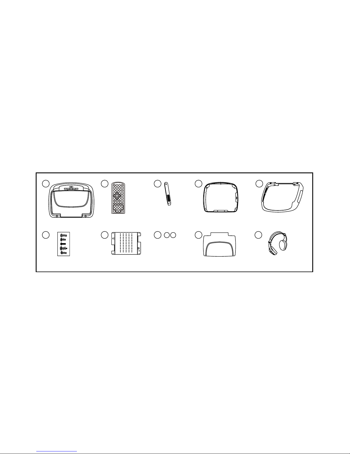
VEHICLE PREPARATION:
1) Locate an accessory power source (+12v when key is in the ACC. and run positions, and 0v when
key is off), and also a good ground generally, these wires can be found at the ignition switch or fuse-
box.
2) The mounting method and location will vary from vehicle to vehicle, so this manual will only focus on
the installation of the VOD10 and related console accessories.
3) Generally, the best location for the video monitor is where the vehicle's factory dome light is
installed. The monitor should be located in such a manner that it can be comfortably viewed by rear
seat passengers.
NEVER INSTALL THE MONITOR IN A PLACE WITHIN THE DRIVER'S VIEW. THIS IS NOT ONLY
DANGEROUS, BUT IT IS ALSO ILLEGAL IN MANY STATES.
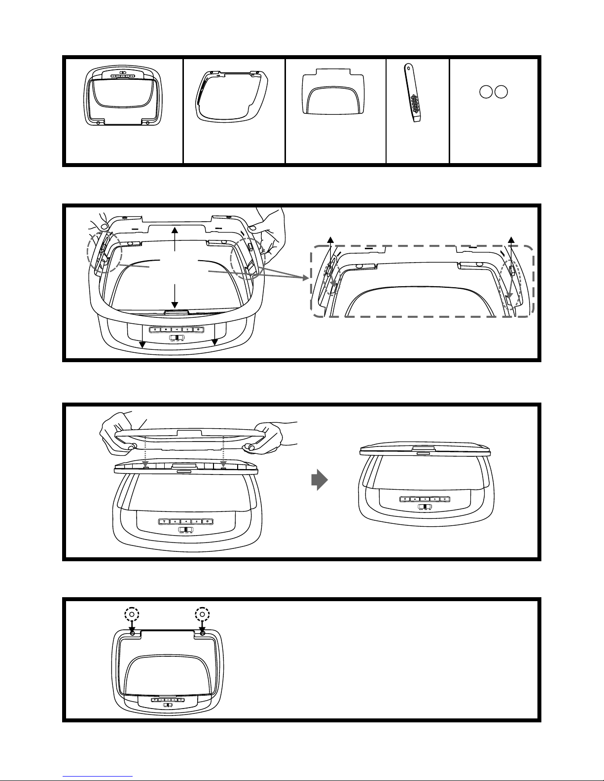
4) Once the mounting location of the monitor has been determined, there may be additional
preparation work necessary, depending on the vehicle structure and installation method. Some of
the steps that may be required are:
A) Removal of the vehicle's dome light
B) If the trim ring will be used, it may have to be trimmed to fit the contour of the vehicle's
headliner. Refer to the "Trim Ring Installation" section in this manual.
GENERAL INSTALLATION APPROACH:
1) Decide upon system configuration and options that will be installed (i.e.: what components, VCP,
Video Game, external amp, wireless headphones, VCP, etc.).
2) Review all manuals to become familiar with electrical requirements and hook ups.
3) Decide upon mounting locations of all components and method of mounting.
4) Prep the vehicle by removing any interior trim necessary to gain access to vehicle's wiring as well as
all areas where interconnecting wire harnesses will need to be located. If any access holes need to
be cut into the vehicle (headliner, other trim components etc.), this should be done now as well.
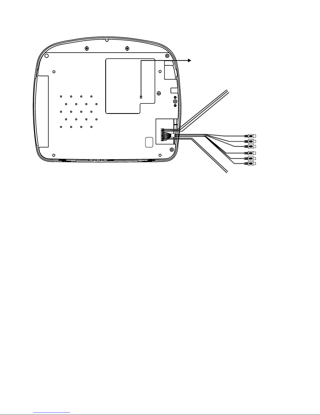
5) Route the wiring harnesses throughout the vehicle as necessary. (Refer to the Wiring Diagrams on
this manual as well as the wiring instructions for the individual components and accessory options
being installed). Be sure that all wiring is protected from sharp edges and is routed in such a manner
that pinched when all components and interior trim are fully installed. Be sure to leave enough slack
in the wiring at each component to allow working room.
6) Remove all A/V system components from their packaging and place them loosely in the vehicle at
their respective locations.
7) Connect all components together (electrically) and verify proper operation of all system functions.
Note: This is best done BEFORE, components have been permanently mounted.
8) After verifying proper operation of the system, proceed to mount of each component.
9) When all components are mounted, recheck function of entire system again to ensure that no wiring
was pinched or connected improperly during final installation.
6
TRIM RING INSTALLATION:
Note: This page only covers special installation considerations for thick trim ring installation. If the video
monitor is to be installed in a vehicle with the thick trim ring, it may need to be trimmed to fit the contour of
the vehicle Headliner.
Note: The trim rings supplied with this unit are not designed to be trimmed.
1) In this installation, the video monitor is mounted directly to the overhead cross-member in the roof
using the mounting screw bosses. These screw bosses should contact the cross-member directly
(i.e.: no gap between the screw boss and the roof structure). Also, be sure that the screws do not
pierce the outer roof skin when fully fastened to the cross-member. The trim ring is attached to the
video monitor using the perimeter screw bosses. It is important that the screws used in this
installation are not over tightened, and that the video monitor and trim ring are mounted in such a
way that the assembly does not distort (or bend) when the mounting screws are tightened. An
alternate method is to use the mounting bracket. First secure the mounting bracket to the cross-
member, then screw the monitor into the mounting bracket. See the drawing in this manual.
2) It is best to mount the video monitor to the roof structure without the trim ring first. There should be a
gap between the headliner and the outer flange of the video monitor. The trim ring should be cut to
fill this gap. Apply masking tape to the outer surface of the trim ring in the areas where the cut will be
made.
3) Mark the cut to follow the necessary contour of the roof. The suggested method of marking is as
follows:
A) First mark the narrowest point of the trim ring on the masking tape. Be careful to consider not
only vertical location, but fore-aft location.
B) Using the handle of a screwdriver, make a “transfer marking tool”. See diagram below. Place
the tool against the roof and the marker against the masking tape on the trim ring. Trace the
cut to be made around the entire perimeter of the trim ring.
C) Cut the trim ring using a sharp utility knife or shears. Make the cut in several passes over the
marked line, each time cutting a little deeper. It is not necessary to cut completely through the
plastic, the cut only need be over 50% of the wall thickness of the plastic. By bending the cut
back and forth several times, the plastic will break cleanly at the cut.
D) Check the fit of the trimmed console and make any minor adjustments necessary.
4) The trim ring can be painted or covered with a material that matches the headliner before
assembling the trim ring to video monitor.
5) The finished trim ring should be attached to the video monitor, then attach the assembly to the roof.
Tape marker to screwdriver.
Starting at your mark for the
lowest point, trace the contour of the roof
Lowest point mark
Cut line
Headliner
7
TRIM RING INSTALLATION:
Supplied screws as below use for install Trim Ring to unit. Please refer illustration below.
A) #4 x 5/16 Self Tapping Screws (1pc)
B) #4 x 7/16 Self Tapping Screws (3pcs)
C) Screws ISO 3 x 8mm Long (5pcs)
A
B
BB
C
C
C
C C
Roof
Roof Support
Headliner
Mounting Bracket
Self-drilling Screws
Trim Ring
Video Unit
M5 Screw
MOUNTING THE TRIM RING
8
1) Make the connections to the vehicle for the 10 pin wiring harness.
2) Connect 2 pin power harness to vehicles electrical system by tapping into an accessory
hot line and a good ground.
3) Verify all functions of the system before final mounting of the finished assembly.
A/V Source Definitions:
1. DVD - Built in DVD
2. AV1 - Signal Harness to 3 RCA Jack Pigtail is used for AV1 input.
3. AUX - AUX input.
*NOTE: Extending the wireless antenna will cause the FM modulator to exceed FCC limits
of wireless transmission. When installing the unit position the antenna for best
reception.
* Antenna for Wireless FM Mod.
** See Antenna Note
WIRING DIAGRAM
9
Dome Light
Power source
10 Pin A/V In Out Harness
Line In-R (Red)
Line In-L (White)
Line In-V (Yellow)
Line Out-R (Red)
Line Out-L (White)
Line Out-V (Yellow)
Power Supply Harness
CONNECTING THE DOME LIGHTS
The dome lights in the video monitor require three connections to the vehicle's wiring. There are two
common types of dome light circuits used, positive or negative switched system. Positive switched
systems supply voltage to the interior lights to turn on, negative switched systems apply ground to
illuminate the bulbs.
To determine which system you have to locate the wires at the dome light:
On a positive switched system, with all the doors closed and the lights out, both wires at the dome light will
rest at ground. When the light is activated, one of these wires will switch to +12 vdc. This is the vehicle's
switching wire.
On a negative switched system, with all the doors closed and the lights out, both wires at the dome light will
rest at + 12vdc. When the light is activated, one of these wires will switch to ground. This is the vehicle’s
switching wire.
For positive systems, connect the violet / brown (Lamp auto) wire to the vehicle's switched wire. Then
connect the red / black (lamp on) wire to a fused constant 12 volt source and the black / red (lamp
common) wire to a good ground. Positive systems are commonly found on Ford vehicles.
For negative systems, connect the violet / brown (Lamp auto) wire to the vehicle's switched wire. Then
connect the red / black (lamp on) wire to a good ground and the black / red (lamp common) wire to fused
constant 12 volt source. Negative systems are commonly found on General Motors and import vehicles.
Note: Some vehicles which incorporate transistorized control of the dome light circuit, such as the 1999
Dodge Caravan, may require that the violet / brown (Lamp auto) wire be connected to the door pin switch
wire, as the additional current draw of the monitor's lights may not be supported by the output of the
vehicles body control computer.
Positive Switched Dome Lighting
Red / black - Lamp on
Factory Dome light circuit
To 12 pin
connector
on Monitor
To
constant
+12vdc
To
constant
+12vdc
Black / red - Lamp common
Purple / brown - Lamp Auto
Factory Door ajar
switch or Body
Control computer
10
Fused
Red / black - Lamp on
To 12 pin
connector
To
constant
To
constant
Black / red - Lamp common
Purple / brown - Lamp Auto
Factory Door ajar
switch or Body
Control computer
Troubleshooting:
SYMPTOM: REMEDY:
No power at Video Monitor Verify +12 VDC on Red wire at 2 pin Power Harness
behind video monitor. Verify ground connection with
continuity test from known good ground to black wire at
2 pin Power Harness
Power but no video or sound Verify that the correct source is selected (i.e.: 1,2,3 or
4). Verify that the source is on and playing a known
good media (such as a videotape). Verify connections at
both ends of the source component harness.
Negative Switched Dome Lighting
11
© 2009 Audiovox Electronics Corp., Hauppauge, NY 11788 128-8566

Other manuals for VOD10 - Car - Overhead LCD Monitor

2

Other Audiovox Car Video System manuals

Audiovox Movies2Go AVXMTGHR1D User manual

Audiovox

Audiovox Movies2Go AVXMTGHR1D User manual

Audiovox MMD92 User manual

Audiovox

Audiovox MMD92 User manual

Audiovox VOH681 User manual

Audiovox

Audiovox VOH681 User manual

Audiovox VM9223 User manual

Audiovox

Audiovox VM9223 User manual

Audiovox VOD705DL - DVD Player With LCD Monitor User manual

Audiovox

Audiovox VOD705DL - DVD Player With LCD Monitor User manual

Audiovox PROV715 User manual

Audiovox

Audiovox PROV715 User manual

Audiovox VOH1041DL User manual

Audiovox

Audiovox VOH1041DL User manual

Audiovox AVT 1498 User manual

Audiovox

Audiovox AVT 1498 User manual

Audiovox VME 9309TSB User manual

Audiovox

Audiovox VME 9309TSB User manual

Audiovox Movies 2 Go MMSV58 User manual

Audiovox

Audiovox Movies 2 Go MMSV58 User manual

Audiovox Mobile Video HR7010PKG User manual

Audiovox

Audiovox Mobile Video HR7010PKG User manual

Audiovox VOD710 - DVD Player With LCD Monitor User manual

Audiovox

Audiovox VOD710 - DVD Player With LCD Monitor User manual

Audiovox HR7DD PKG User manual

Audiovox

Audiovox HR7DD PKG User manual

Audiovox 1187025 User manual

Audiovox

Audiovox 1187025 User manual

Audiovox Mobile Video 128-8607 User manual

Audiovox

Audiovox Mobile Video 128-8607 User manual

Audiovox VMO 5020 V User manual

Audiovox

Audiovox VMO 5020 V User manual

Audiovox VBP4000 - VBP 4000 DVD Player User manual

Audiovox

Audiovox VBP4000 - VBP 4000 DVD Player User manual

Audiovox VME 9314 TS User manual

Audiovox

Audiovox VME 9314 TS User manual

Audiovox Movies2Go 128-8290 User manual

Audiovox

Audiovox Movies2Go 128-8290 User manual

Audiovox VOD1048 User manual

Audiovox

Audiovox VOD1048 User manual

Audiovox Rampage VBP1000 User manual

Audiovox

Audiovox Rampage VBP1000 User manual

Audiovox SLOT-IN AVD400 User manual

Audiovox

Audiovox SLOT-IN AVD400 User manual

Audiovox PAV1510DTV Manual

Audiovox

Audiovox PAV1510DTV Manual

Audiovox VOD129 User manual

Audiovox

Audiovox VOD129 User manual

Popular Car Video System manuals by other brands

Boss Audio Systems Vision BVT5.6 user manual

Boss Audio Systems

Boss Audio Systems Vision BVT5.6 user manual

Boss Audio Systems BV-T6.0 user manual

Boss Audio Systems

Boss Audio Systems BV-T6.0 user manual

Boss Audio Systems BVCP9850W user manual

Boss Audio Systems

Boss Audio Systems BVCP9850W user manual

Alpine X800D-S906 installation manual

Alpine

Alpine X800D-S906 installation manual

Vizualogic A-2000 installation manual

Vizualogic

Vizualogic A-2000 installation manual

Soundstream VCM-112 owner's manual

Soundstream

Soundstream VCM-112 owner's manual

Mazda 3 Sedan 2019 manual

Mazda

Mazda 3 Sedan 2019 manual

Cartechno NA-VL2DVD900 installation instructions

Cartechno

Cartechno NA-VL2DVD900 installation instructions

Premier SCR-4328DUSD user manual

Premier

Premier SCR-4328DUSD user manual

Clarion NX602 quick start guide

Clarion

Clarion NX602 quick start guide

Xenarc 700IDT Owner's records

Xenarc

Xenarc 700IDT Owner's records

Eonon D1303 user manual

Eonon

Eonon D1303 user manual

iBeam TE-RVMCBT product manual

iBeam

iBeam TE-RVMCBT product manual

MAXTEK 61278 user guide

MAXTEK

MAXTEK 61278 user guide

HOLDEN JH CRUZE System handbook

HOLDEN

HOLDEN JH CRUZE System handbook

Advent ADV10A Operation manual

Advent

Advent ADV10A Operation manual

r.LiNK RL4-R40 manual

r.LiNK

r.LiNK RL4-R40 manual

Sound Storm SH7CM user manual

Sound Storm

Sound Storm SH7CM user manual

manuals.online logo
manuals.online logoBrands
  • About & Mission
  • Contact us
  • Privacy Policy
  • Terms and Conditions

Copyright 2025 Manuals.Online. All Rights Reserved.