Aulisa Guardian Angel Rx GA1000 User manual

Guardian Angel™
GA1000
Digital Vital Sign
Monitoring System
TM
Rx
At the time of publication, this manual is believed to be accurate and
up-to-date. In the interest of continued product development,
Taiwan Aulisa Medical Devices Technologies, Inc. reserves the right
to make changes and improvements to this manual and the products
described within at any time, without notice or obligation.
References to “Aulisa” in this manual shall imply
Taiwan Aulisa Medical Devices Technologies, Inc.
Aulisa is a registered trademark of
Taiwan Aulisa Medical Devices Technologies, Inc.
Taiwan Aulisa Medical Devices Technologies, Inc.
No. 218-2, Chong Yang Rd., Nangang Dist.
11573 Taipei City , Taiwan
Tel +886-2-2655-7297
Distributed by
Aulisa Medical USA, Inc.
999 Commercial Street, Suite 208
Palo Alto, CA 94303,USA
www.aulisa.com
©2019 Taiwan Aulisa Medical Devices Technologies, Inc.
Read this entire manual carefully before using Aulisa GA1000
Digital Vital Sign Monitoring System.
TM

..............................................................................
......... .................................................................
Indications for Use ............................................................................
Principle of Operation
System Overview
....................................................................
..........................................................................
Device Overview ...........................................................................
Displays, Indicators, and Controls ..............................................
Setting up Aulisa GA1000 System
Device Pairing
Verifying System Operation
Shutting off the System
..............................................
........................................................
........................................................
Alarms
Adjusting Alarm Limits
Alarm Delay Feature
.........................................................
.........................................................
Default Alarm Settings
Charging the Oximeter Box
Powering the Display Unit
..................................................................
Cleaning and Disinfection
......
Device Performance
Manufacturer's Declaration
FCC Compliance
..............................................................................
..............................................................................
..............................................................................
.........................................................
....................................................................
..............................................
..............................................
....................................................................
.........................................................
..............................................................................
....................................................................
.........................................................
.........................................................
....................................................................
..............................................
..............................................................................
..................................................................
1
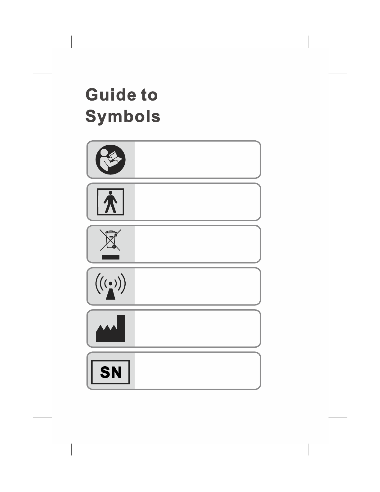
Indicates s arate collection for electricep al
electronic equipment (WEEE). and
Type BF- isolationApplied Part (patient
from electrical shock )
Non-ionizing electromagnetic radiation.
Equipment includes RF transmitters.
Interference may occur in the vicinity of
equipment marked with this symbol.
Refer to instruction manual
M actureranuf
Seri beral num
1
Prescripti e onlyon us
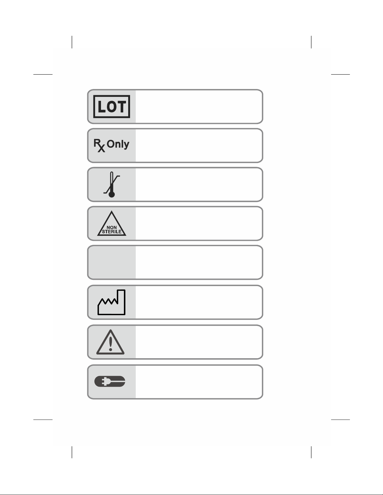
Non-sterile
Temperature limit
Lot number
Classification for water ingress and
particulate matter
Charging Port
IP22 Classification for water ingress and
particulate matter
Date of Manufacturer
Caution
IP22
2

3
1. Aulisa GA1000 Digital Vital Sign Monitoring System
is intended only as an adjunct in patient assessment.
It must be used in conjunction with other methods of
assessing clinical signs and symptoms.
2. A functional tester cannot be used to assess the
accuracy of an oximeter sensor cable or an oximeter
box. Aulisa GA1000 Digital Vital Sign Monitoring
System does not require calibration.
3. Aulisa GA1000 Digital Vital Sign Monitoring System
readings may be affected by the use of
an electrosurgical unit.
4. Only use the sensor cables manufactured by
Aulisa. These sensor cables are manufactured to
meet the accuracy specifications for Aulisa GA1000
Digital Vital Sign Monitoring System. Using other
manufacturers' sensor cables can result in
improper device performance and patient injury
may occur.
5. The operator must verify the compatibility of the
sensor cable with Aulisa GA1000 Digital Vital Sign
Monitoring System before use, otherwise patient
injury can result.
6. As with all medical equipment, carefully route all
cables to reduce the possibility of entanglement,
strangulation or injury to the patient.
1. Do not use any part of this system in an MRI
environment.
2. Explosion Hazard: Do not use this system in an
explosive atmosphere or in the presence of
flammable anesthetics or gases.
3. This device is not a replacement for a caregiver.
Contraindications
Warnings

4
7. Be careful with small parts that can be removed
from the device and swallowed, such as port
covers. They are hazardous to children.
8. Excessive pressure to the sensor probe application
site for prolonged periods may cause
damage to the skin beneath the sensor probe.
9. Do not use a damaged sensor cable. If the sensor
cable is damaged in any way, discontinue use
immediately and replace the sensor cable.
10. Do not use in or around water or any other liquid
when AC power adaptor is used.
11.Only use Aulisa GA1000 Digital Vital Sign
Monitoring System with charging adaptors
provided by Aulisa.
12. Aulisa GA1000 Digital Vital Sign Monitoring
System is designed to determine functional
oxygen saturation, the percentage of arterial
oxygen saturation of functional hemoglobin.
Significant levels of dysfunctional hemoglobin,
such as methemoglobin, might affect the accuracy
of the measurement.
13. Use Aulisa GA1000 Digital Vital Sign Monitoring
System only when the components are installed
within the specified distances from the monitored
patient – approximately 10 meters (32.8 feet)
spherical radius from the Oximeter Box to the
wireless Display Unit. Moving outside this range
may cause missing, lost, and/or inaccurate data.
14. Loss of monitoring can result if any objects hinder
the pulse measurement. Ensure that no blood flow
restrictors (e.g. blood pressure cuff) hinder pulse
measurements.
15. This product is not a substitution for physician
supervision.
16.Always refer to Instructions For Use for full
warnings and instructions.
17.Failure to follow instructions and warnings may
result in serious injury or death.

5
Cautions
1. This equipment complies with International
Standard IEC 60601-1-2: 2014 for electromagnetic
compatibility for medical electrical equipment
and/or systems. This standard is designed to
provide reasonable protection against harmful
interference in a typical medical installation.
However, because of the proliferation of
radio-frequency transmitting equipment and other
sources of electrical noise in healthcare and other
environments, it is possible that high levels of
interference due to close proximity or strength of
a source might disrupt the device's performance.
2. If Aulisa GA1000 Digital Vital Sign Monitoring
System fails to respond as described, discontinue
use until the situation is corrected by qualified
personnel.
3. Cardiogreen and other intravascular dyes may
affect the accuracy of SpO measurements.
2
4. The sensor probe might not work on cold
extremities due to reduced circulation. Warm or rub
the finger to increase circulation, or reposition the
sensor probe.
5. Aulisa GA1000 Digital Vital Sign Monitoring
System might misinterpret motion as good pulse
quality. Minimize motion of the monitored site.
6. Excessive ambient light may affect the accuracy
of the measurement.
7. Some nail polish colors or artificial nails can
reduce light transmission and affect SpO2
accuracy.
8. Inspect and relocate the sensor probe application
site at least every 6 to 8 hours to ensure correct
sensor probe alignment and skin integrity. Patient
sensitivity to a sensor probe may vary due to
medical status or skin condition.
9. Do not place liquids on top of the device.
10. Do not immerse the device or any of the
components in any liquids.
11. Do not use caustic or abrasive cleaning agents on
the device.
12. Do not gas sterilize or autoclave this pulse
oximetry system.

6
13. Batteries might leak or explode if used or
disposed of improperly.
14. Follow local governing ordinances and recycling
instructions regarding disposal or recycling of the
device and device components, including
batteries.
15. Do not subject the system to extreme hot or cold
temperatures, humidity, or direct sunlight.
16.Do not fasten the Wristband too tightly around the
patient's wrist. Inaccurate readings and patient
discomfort could result.
17.The device is not for use during exercise.
7
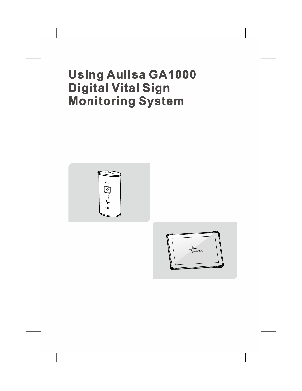
This chapter describes how to use Aulisa GA1000 Digital Vital Sign
Monitoring System (hereinafter referred to as Aulisa GA1000 system).
The system includes the following components and accessories*
*The kit may come with different configurations of Oximeter Sensor
Cables.
Oximeter Box (OB)
Display Unit (DU)
8
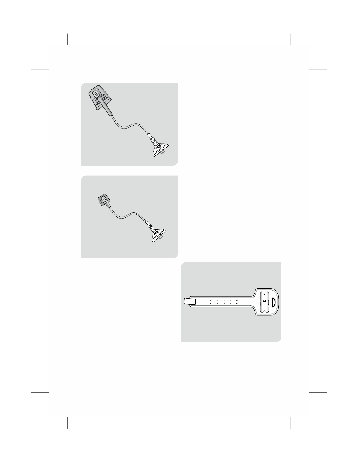
Adult Oximeter Sensor Cable
Wristband
Pediatric Oximeter Sensor Cable
9
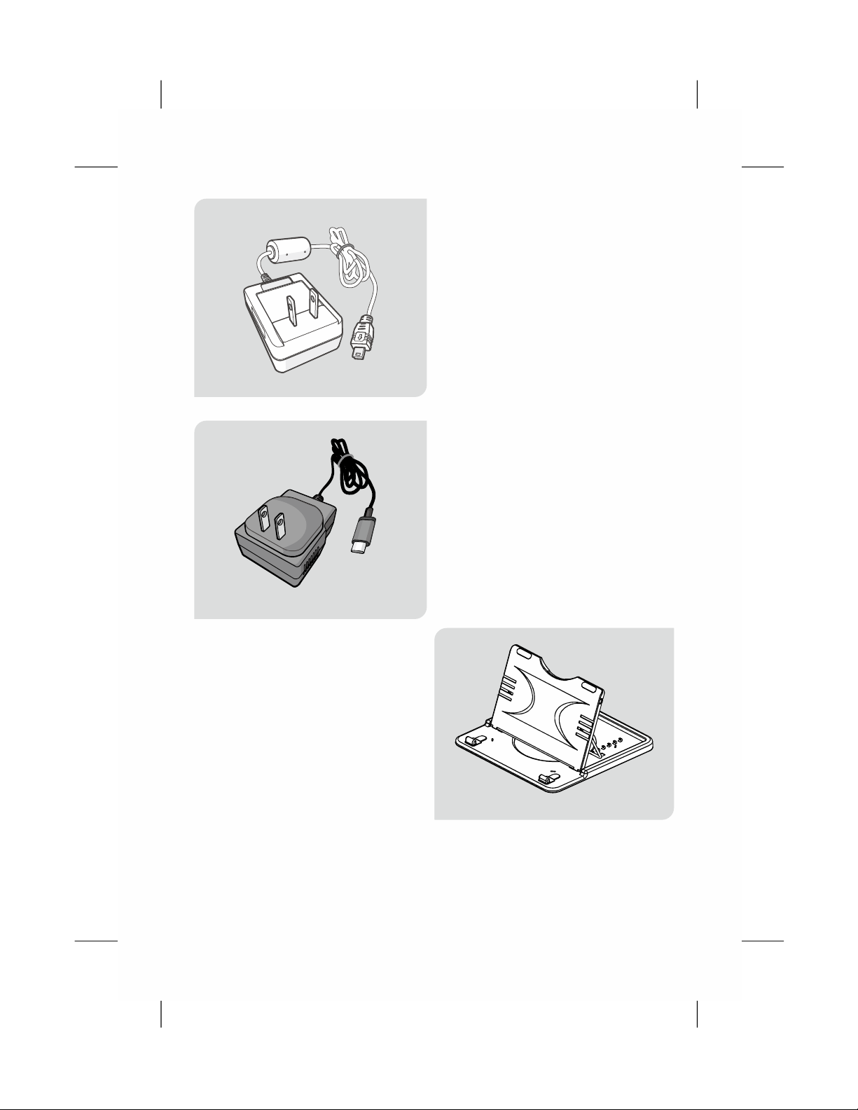
Charging Adaptor -
Oximeter Box
Stand- Display Unit
Charging Adaptor -
Display Unit
10
Intended Use
Principle of Operation
Aulisa GA1000 Digital Vital Sign Monitoring System measures SpO
2
and pulse rate based on non-invasive light-emitting diode (LED)
transmittance technology, measuring the absorbance of red and
infrared light passed through the perfused tissue during each pulse.
It can be operated by the caregiver or by the patient.
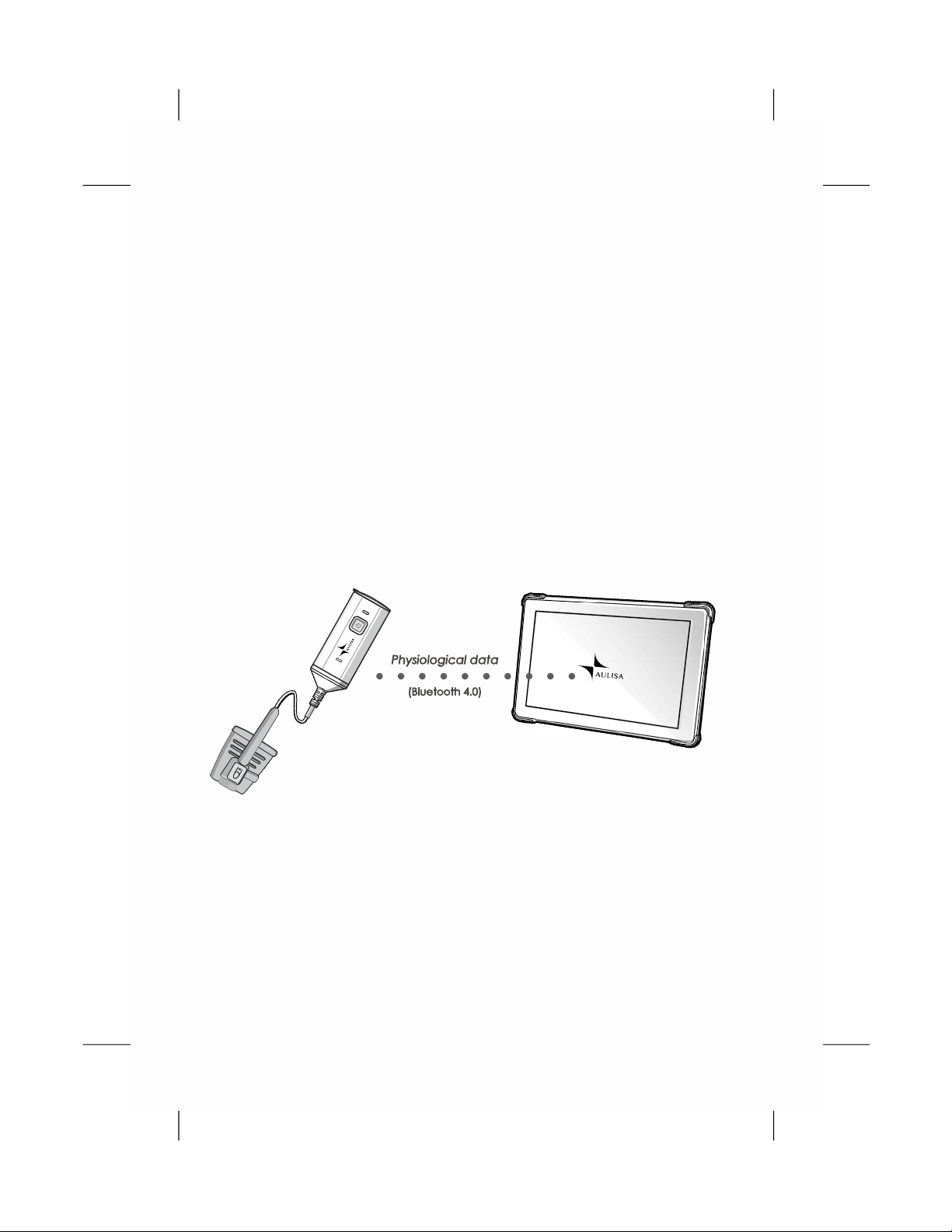
System Overview
The Guardian Angel Rx GA1000 Digital Vital Sign Monitoring System
is indicated for use in measuring and displaying functional oxygen
saturation of arterial hemoglobin (SpO ) and pulse rate of adult and
2
pediatric patients. It is indicated for spot-checking and / or continuous
monitoring of patients during non-motion and under well-perfused
conditions. The intended environment of use is hospital. This system
is a reusable device.
TM
11
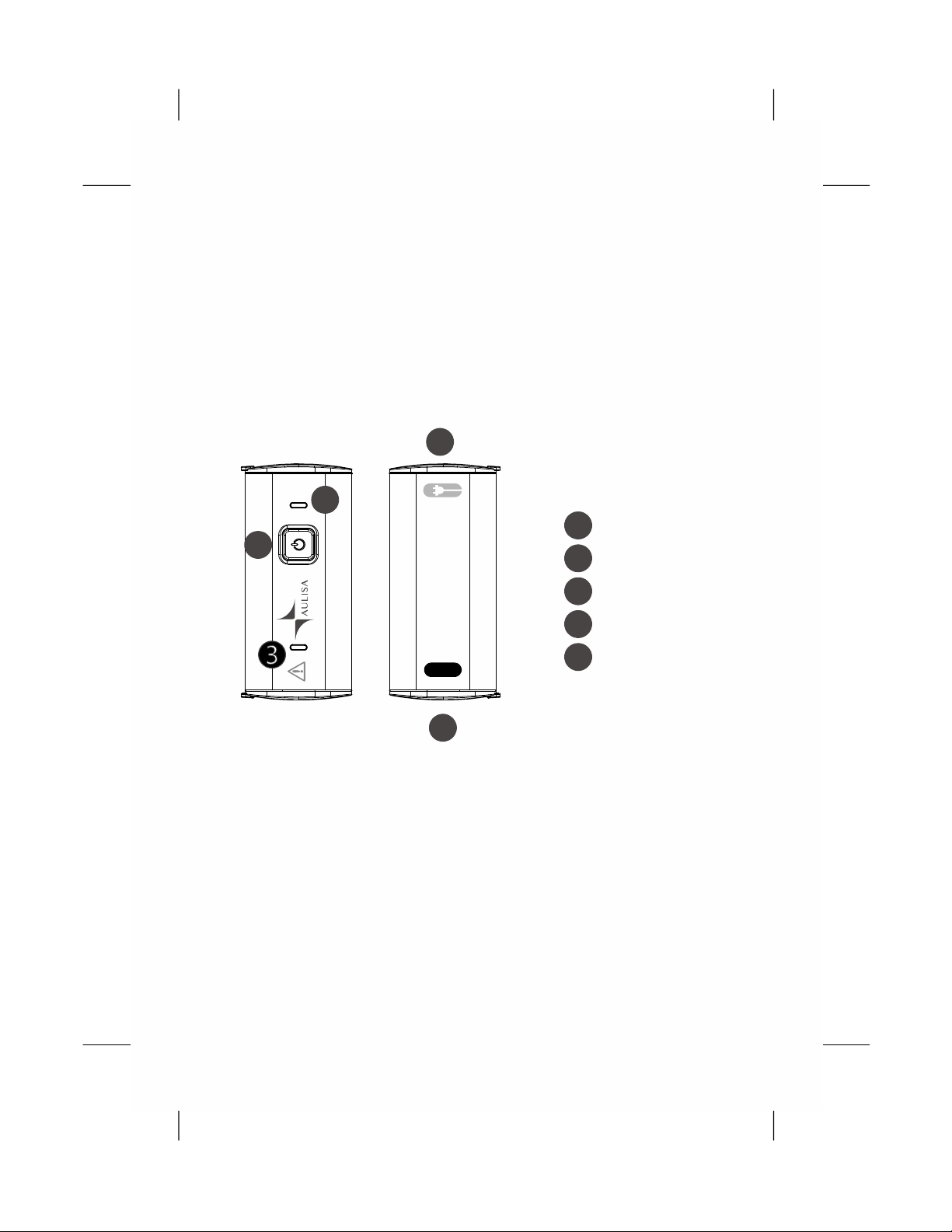
Device Overview
Oximeter Box
The Oximeter Box includes a Bluetooth transmitter and a sensor chip,
which is worn by the patient for vital sign monitoring. It features a sensor
chip along with electronics for vital sign measuring and analyzing.
The Oximeter Box must be used within 10 meters (32.8 feet) from the
Display Unit.
1
2
3
4
5
Power button
Power LED
Alarm LED
Charging port
Sensor cable port
SEN S OR
1
2
4
5
Front View Back View
12
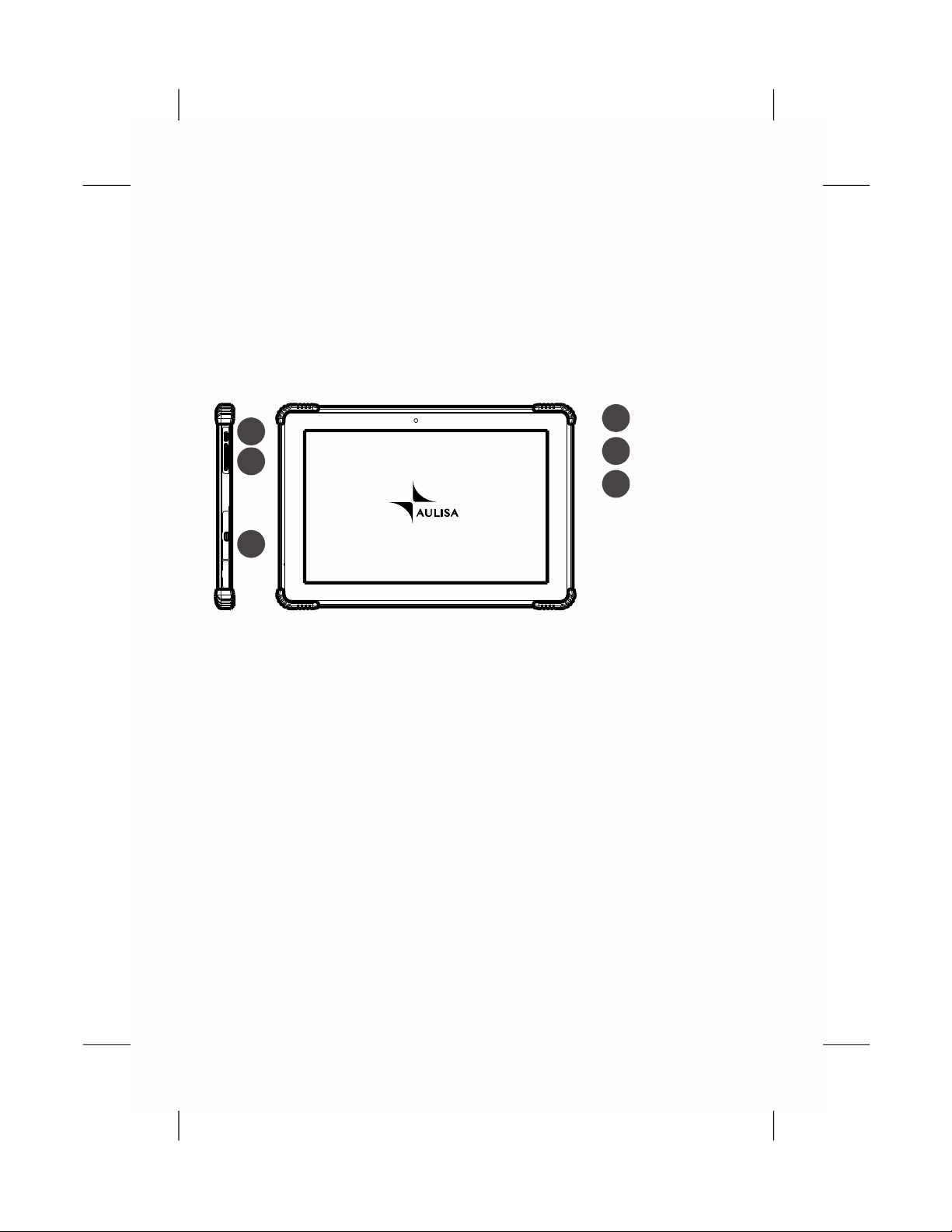
Display Unit
The Display Unit features a 10 1" LCD multi touch display with . -
Bluetooth technology. The Display Unit displays real-time vital signs
measured by the Oximeter Box.
The Display Unit will display informational text messages, alarm text
messages, and beep made audible upon an alarm condition trigger
event.
1
2
Power button
Volume button
3Charging port
1
2
3
NOTE:It is recommended that the Display Unit be placed on the
stand provided.
NOTE:Only use fingers to operate keys on the touch screen.
NOTE:Close the cover of charging port when the charging adaptor
is not in use.

13
Displays, Indicators, and Controls
This section describes the displays, indicators, and controls for the
Aulisa GA1000 System.
Display Icons and Indicators
This icon identifies the window
showing the pulse rate in bpm.
Pulse Rate
This icon identifies the window
showing the functional blood
oxygen saturation in percent.
Blood Oxygen
This icon identifies the window
showing the pulse amplitude.
Pulse
Amplitude
When the vital signs cannot be
measured, the Display Unit
shows dashes - - - in each of
“ ”
the vital sign windows.
No data
SpO2 %
When the vital sign values are
inadequate, the Display Unit
shows ? beside the value.
“ ”
Inadequate
data
This icon displays whether the
Oximeter Box and the Display
Unit are connected via Bluetooth.
It will turn blue once the
Oximeter Box is paired with the
Display Unit.
Bluetooth
Connection
Status
This icon displays whether there
is a finger inserted in the sensor.
A system alarm will be displayed
on the Display Unit if no fingers
are detected.
Measurement
Site Status
bpm
Pulse Amplitude
Indicator
This icon displays the pulse
signal strength.

14
This icon displays whether the
sensor cable is connected to
the Oximeter Box. A system
alarm will be displayed on the
Display Unit if the cable is
disconnected.
Sensor Cable
Connection Status
These icons signify the battery
level at Full, Medium, or Low.
A medium priority system alarm
will be displayed on the
Display Unit when the
Oximeter Box battery is low.
Battery Level of
Oximeter Box
These icons signify the battery
level of the Display Unit.
A medium priority system alarm
will be displayed on the
Display Unit when the
Display Unit battery is low.
Battery Level of
Display Unit
This icon identifies an alarm
condition exists.
!!! represents high priority and
!! represents medium priority
Alarm Indicator
This icon indicates that the
alarm is turned off for the
corresponding physiological
condition.
Alarm Off
This icon indicates that the
alarm audio is silenced for
2 minutes.
Audio Paused
This icon indicates that the
alarm audio is silenced
permanently.
Audio Off
15
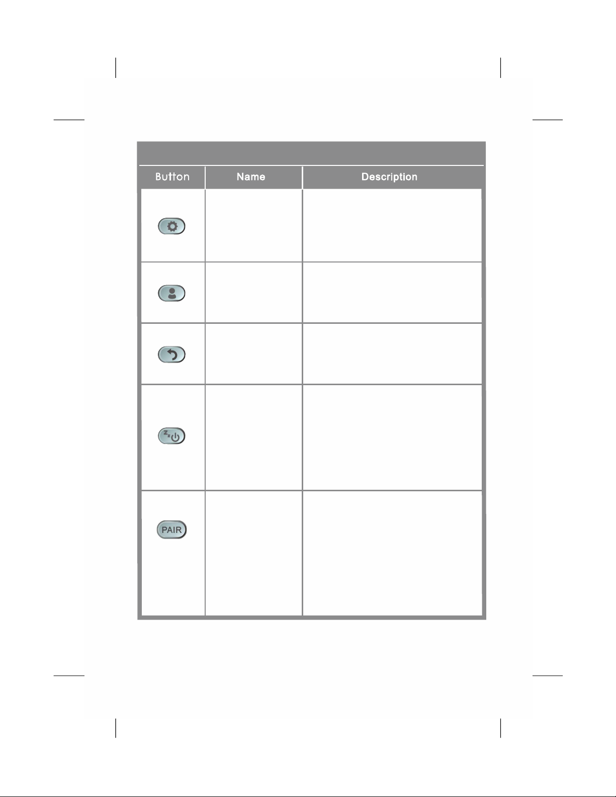
Device Pairing
This button appears on the top
right corner of the MAIN screen
when the system is disconnected.
Tap on the button to force the
system to pair.
NOTE: The Oximeter Box must
be placed within 10 meters from
the Display Unit.
Software Control Buttons
System Settings
Tap on this button on the top
right corner of the MAIN screen
to access the settings menu of
the system.
Return to
Previous Screen
Tap on this button on the top
right corner of the MAIN screen
to return to the previous page.
Sleep Mode
Tap on this button on the top right
corner of the MAIN screen to let
the Display Unit enter sleep
mode. To wake up the Display
Unit, tap on the blank screen
and use finger to swipe to the
right.
Edit Profile
Tap on this button to edit a patient
profile, including name, weight,
gender, date of birth, and location.
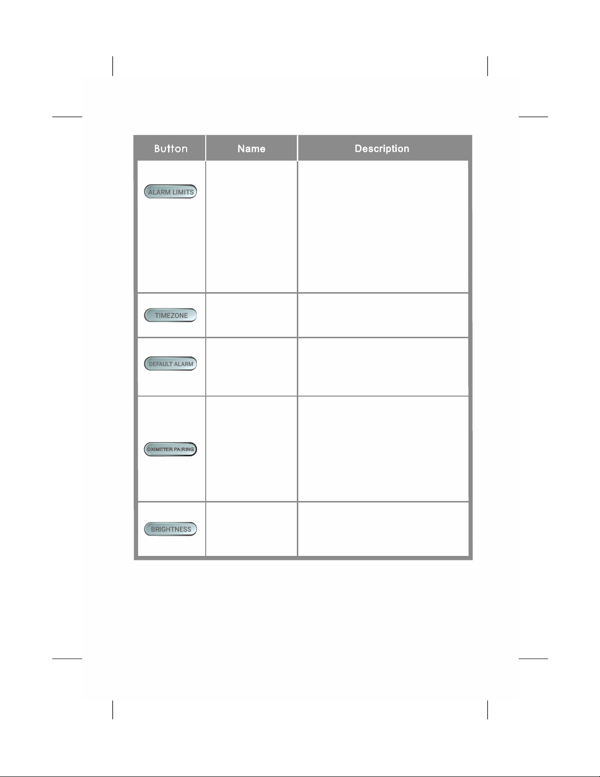
16
In the settings menu, tap on this
button to set the brightness of
the display.
Set Display
Brightness
Set Timezone
Scan
Oximeter Box
QR Code
In the settings menu, tap on this
button to select the correct
timezone.
In the settings menu, tap on this
button and scan the barcode on
the back of the Oximeter Box to
manually pair the desired
Oximeter Box to the Display
Unit. (See “Device Pairing”
section on page 22 for more
information.)
Set Alarm Limits
Tap on this button on the MAIN
screen to adjust the alarm limits
for each vital sign.
(See “Alarm and Limits” section
on page 25 for more information
on adjusting the alarm limits.)
NOTE: The button is operable
only when the wireless
connection is established.
Restore Default
Alarm
In the settings menu, tap on this
button to restore alarm limits to
manufacture-configured values.

17
Pause Alarm
Audio
This button appears on the MAIN
screen when an alarm is
triggered. Tap on the button to
temporarily silence the alarm
audio of the current triggered
alarm event for 2 minutes.
Turn Off Alarm
Audio
The button appears on the MAIN
screen when an alarm is
triggered. Tap on the button to
permanently silence the alarm
audio of the current triggered
alarm event.
Table of contents
Other Aulisa Medical Equipment manuals

Aulisa
Aulisa Guardian Angel GA2000 Series User manual

Aulisa
Aulisa Guardian Angel GA1000 Series User manual

Aulisa
Aulisa Guardian Angel Rx GA2000 User manual

Aulisa
Aulisa Guardian Angel Rx GA1001 User manual

Aulisa
Aulisa Guardian Angel Rx Guardian Angel Rx Lite GA2000... User manual

Aulisa
Aulisa Guardian Angel Rx GA2000 User manual
Popular Medical Equipment manuals by other brands


Getinge
Getinge Arjohuntleigh Nimbus 3 Professional Instructions for use

Mettler Electronics
Mettler Electronics Sonicator 730 Maintenance manual

Pressalit Care
Pressalit Care R1100 Mounting instruction

Denas MS
Denas MS DENAS-T operating manual

bort medical
bort medical ActiveColor quick guide

AccuVein
AccuVein AV400 user manual


