MIR Spirotel User manual

Spirotel®
Page 1 of 37
Rev.1.0
Service Guide
Spirotel®
Service guide
Rev. 1.0
Date issued 01.07.2013
Date of approval 28.02.2014

Page 2 of 37
Rev.1.0
INDEX
1. INTRODUCTION ...........................................................................................................................................4
1.1. INTRODUCTORY REMARKS 4
1.1.1. General Aspects 4
1.1.2. Safety Aspects 4
1.1.3. Legal Aspects 4
1.1.4. Environmental Aspects 4
1.2. DATA REGISTRATION 5
1.2.1. Equipment and customer registration / Service file 5
1.2.2. Configuration register 5
1.2.3. Product documentation 5
1.2.4. Technical modifications 5
1.2.5. Product evaluation 5
1.2.6. Additional Information 5
1.2.7. Installation 6
1.3. GENERAL 6
1.3.1. Technical Data 6
1.3.1.1. New spirotel unit 6
1.3.1.2. Battery charger 7
1.4. STANDARDS APPLIED 7
2. HARDWARE DESCRIPTION.........................................................................................................................7
2.1. MAINBOARD MODULE 7
2.1.1. Charging controller for battery pack (IC7 LTC 4067) 8
2.1.2. Room temperature sensor 8
2.1.3. USB communication port 8
2.1.4. Oximetry port 8
2.2. DISPLAY MODULE 9
2.3. TURBINE FLOWMETER 9
3. MAINTENANCE ........................................................................................................................................... 10
3.1. GENERAL 10
3.2. TEST EQUIPMENT 10
3.3. CHECKLIST 10
3.3.1. Functional test 10
3.3.1.1. Self test 11
3.3.1.2. Software version 11
4. REPLACEMENT PROCEDURES ................................................................................................................ 11
4.1. General 11
4.2. Cover 11
4.2.1. Opening the device 12
4.3. PCBs and components 13
4.3.1. Removing and replacing the turbine sensor strip 13
4.3.2. Removing and replacing the display 14
4.3.3. Touch Screen Calibration 14
4.3.4. Removing and replacing the internal battery pack 15
4.3.5. Turbine 17
4.3.5.1. Cleaning the reusable turbine 17
4.3.5.2. Calibration of the reusable turbine 18
4.3.6. Internal software upgrade procedure 18
4.4. Oximeter module 19
4.4.1. Replacing of the oximetry module 19
4.5. Testing procedures 20
4.5.1. Testing procedures for devices with oximeter 20
4.5.2. Testing procedures for devices without oximeter 25
5. SPARE PARTS ................................................................................................................................................26
5.1. ORDERING 26
5.2. DELIVERY 26
5.2.1. Ordering PCBs 26
5.2.2. Warranty claims 26
5.3. RETURN SHIPMENTS 26
6. TROUBLESHOOTING .................................................................................................................................27
6.1. The device does not switch on 27
6.2. The LCD does not display 27

Page 3 of 37
Rev.1.0
6.3. The battery pack is not working correctly 28
6.4. The Bluetooth printer does not print 28
6.5. The device does not measure spirometry at all 29
6.6. The device does not measure spirometry correctly 29
6.7. The device does not measure oximetry at all 30
6.8. The device does not measure oximetry correctly 30
6.9. The data communication via USB does not function 31
6.10. Index of components 31
APPENDIX A: SPARE PARTS LIST ......................................................................................................................32
APPENDIX B: SERVICE INFO (Product Change Notes).....................................................................................35
APPENDIX C ..........................................................................................................................................................36
ANNEX....................................................................................................................................................................37

Page 4 of 37
Rev.1.0
1. INTRODUCTION
1.1. INTRODUCTORY REMARKS
1.1.1. General Aspects
The spirometers from the product group MIR043 are marketed under the label new spirotel.
This manual has been written for technicians involved in the service of the new spirotel. Service can be carried out by the
service organization of the manufacturer or by any other technician authorized by MIR srl.
The manufacturer will not be held responsible for the results of maintenance or repairs by unauthorized persons.
1.1.2. Safety Aspects
Safe execution of the procedures in this manual requires technical experience and general knowledge of safety precautions.
Before you start any operation on the unit, you must have first read both the User and this Service
Manual.
Warnings, Cautions and Notes are used throughout this manual to bring special matters to the immediate attention of the
reader.
Warning The Warning concerns danger to the safety of the technician or user.
Caution The Caution draws attention to an action which may damage the equipment.
Note The Note points out a statement deserving more emphasis than the general text, but which does not
deserve a Warning or Caution.
Warning
In order to prevent unforeseen incidents, keep away from sensitive electronic devices. Inside the new spirotel,
there are low voltages and very low currents, so these represent no danger for persons with experience and with a
general knowledge of safety precautions.
The sequence of steps in a procedure may also be important from the point of view of personal safety and prevention of
damage, therefore never change the sequence of steps or alter any procedure.
Warning
Batteries may explode if defective or damaged or disposed of in fire. Do not short-circuit the batteries!
1.1.3. Legal Aspects
This manual and the information herein are property of MIR srl (Rome, Italy).
Copying this manual in whole or in part is strictly forbidden.
MIR srl disclaims any responsibility for personal injury and/or damage to equipment caused by:
negligence or disregard of a Warning or Caution
deviation from any of the prescribed procedures
execution of activities which are not prescribed
ignorance of the general safety precautions for handling tools and the use of electricity
incorrect or unreasonable use
1.1.4. Environmental Aspects
Please dispose properly of any items replaced, following all the local regulations.
All components (housing, PCBs, batteries, electronic and disposable parts, etc.) must be disposed of according to the
relevant local regulations.

Page 5 of 37
Rev.1.0
1.2. DATA REGISTRATION
1.2.1. Equipment and customer registration / Service file
From the point of view of safety and product liability the following data must be registered for each unit:
Equipment data
Model, REF code and serial number
Customer data
date of purchase
name and full address of the customer
Service data
log of all service activities
Configuration data
the actual configuration of the equipment (hardware and software versions)
The distributor (through their dealer and/or service organization, if any) is responsible for maintaining these records and
they must be able to provide these data when requested.
1.2.2. Configuration register
A configuration file gives the serial numbers and/or batch numbers of main sub-assemblies and/or important parts of each
unit. The parts listed in a configuration file are defined as registered parts. For example parts as mainboards, display,
batteries and internal software.
Note
MIR srl has the original configuration file of each unit sold. Any possible changes in the original configuration of
the supplied units must be filed and the distributor must be able to provide this data.
1.2.3. Product documentation
The documentation set for the new spirotel includes a User Manual. The User Manual is a recommended item for all
service engineers. The user manual is available in the following languages:
English
Spanish
German
French
Italian
Polish
1.2.4. Technical modifications
This publication could include technical inaccuracies or typographical errors. Changes are periodically made to the
information herein; these changes will be published as Service Info in appendix B of this Service Manual.
Note
Some functions described in this manual may not be activated in the present software or hardware version. For
detailed information, please refer to the User Manual.
1.2.5. Product evaluation
In order continuously to improve the quality of our products, MIR srl requests that the service organizations should report
any device issue which may be discovered. When the same issue regularly occurs or when a safety issue occurs, MIR srl
would like you to send us a product complaint report. The report must contain the name, the type of product, a detailed
description of the problem, the frequency of the same problems, the quantity of sold equipment and your solution to the
problem (if any).
1.2.6. Additional Information
Please do not hesitate to contact MIR if you require additional information.
Manufacturer’s address:

Page 6 of 37
Rev.1.0
MIR srl
Medical International Research
Via del Maggiolino, 125
00155 Rome
Italy
Tel.: +39/06/2275 4777
Fax.: +39/06/2275 4785
Email: [email protected]
1.2.7. Installation
Warning:
Before using new spirotel, check internal battery pack charge level.
turn on the NEW SPIROTEL by pressing and release
the power key placed in the middle on the bottom of the
device
Check battery level on the upper right of the display as
shown in the image.
1.3. GENERAL
New spirotel is an “open circuit system” for the measurement of inspiratory and expiratory lung function parameters and
oximetry values, such as pulse rate and SpO2. It is suitable for basic lung function analysis of the mechanical respiratory
tract parameters. Three different respiratory tests can be performed:
the forced vital capacity test (FVC),
the slow Vital Capacity test (VC/IVC)
the Maximum Voluntary Ventilation test (MVV)
New spirotel has been designed and manufactured to ensure the highest level of safety and the unit fully complies with the
stringent international EN 60601-1 and EN 60601-1-2 standards.
1.3.1. Technical Data
1.3.1.1. New spirotel unit
Max. current inside the unit (GSM switched OFF)
120 mA (with LCD at the maximum brightness)
Max. current inside the unit (GSM switched ON)
200 mA (with LCD at level 7 of 31)
Internal batteries
Rechargeable Battery pack Li-ion 3.7 V 1100mAh
Approval
CE 0476 EC mark for Medical Devices
FDA
Dimensions
88x74x38 mm
Weight
Central unit 151g (including battery pack)
Volume range
10 L
Flow range
± 16 L/s
Volume accuracy
± 3% or 100 mL
Flow accuracy
± 5% or 250 mL/s
Dynamic resistance at 12 L/s
< 0,5 cmH2O/L/s
Type of electrical protection
Class II device
Level of protection against direct or indirect contact
Category BF apparatus
Level of water ingress protection
IPX1 device, protected against water drops
Level of assurance of use in the presence of an anaesthetic mix
flammable with air or oxygen or protoxide of nitrogen
Apparatus not suitable
Conditions of use
Apparatus for repeated use
Storage conditions
Temperature: MIN -20 °C, MAX +60 °C

Page 7 of 37
Rev.1.0
Humidity: MIN 10% RH; MAX 95%RH
Operating conditions
Temperature: MIN +10 °C, MAX +40 °C
Humidity: MIN 10% RH; MAX 95%RH
1.3.1.2. Battery charger
Battery charger supply: Voltage = 5VDC, Current = 1300 mA
Permissible mains voltage var.: 100 V-240 V
Mains frequency: 50 –60 Hz
Max. current: 1300 mA at 5 VDC
1.4. STANDARDS APPLIED
According to rule 10 of the European directive 93/42/CEE the device is classified as Class IIa
EN 60601-1 Electronic medical apparatus. Part 1: General safety standards
EN 60601-1-1 Electronic Medical apparatus. Part 1: General safety standards 1. Collateral standard: Safety requirements
for medical electronic systems
EN 60601-1-2 Electronic medical apparatus. Part 1: General safety standards 2. Collateral standard: Electromagnetic
compatibility –Requirements and tests
EN 60601-1-4 Electronic medical apparatus. Part 1: General safety standards 4. Collateral standards: Programmable
medical electronic systems
UNI CEI EN ISO 14971 Medical devices: application of risk management to medical devices
ATS/ERS TASK FORCE: Standardisation of lung function testing (volume 26/numbers 1-5/2005)
Health Canada Medical Device Regulation: P.C. 1998-783 del 7 /5/1998
SANS 451:2008 Spirometry —Generation of acceptable and repeatable spirograms FDA Regulations
Japanese MHLW Ministerial Ordinance 169: 2004
2. HARDWARE DESCRIPTION
Because of the modular design of the new spirotel, the description is on a block diagram level.
2.1. MAINBOARD MODULE
The mainboard module translates the input signal from the turbine flowmeter into spirometry values and compares them
with the predicted values calculated with the parameters age, sex, height, weight and ethnic group. Test results are displayed
on a LCD and can be printed on paper with an external printer or sent to e-mail or a server via GSM module. Spirometry
test data are stored into memory or on the server and are available for later use.

Page 8 of 37
Rev.1.0
The mainboard module also makes a calculation using the oximetry input signal; from this signal collected at a 16
msec/frequency the percentage value of oxygen saturation in the blood and the heart beat values are obtained, which are
oximetry parameters.
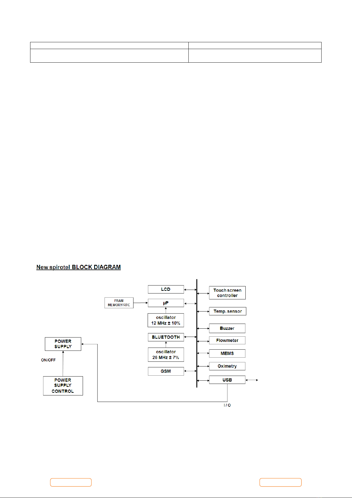
The mainboard module includes:
-Main Microcontroller
-FLASH memory with device configuration and spirometry data
-FRAM IC with non volatile memory and real time clock
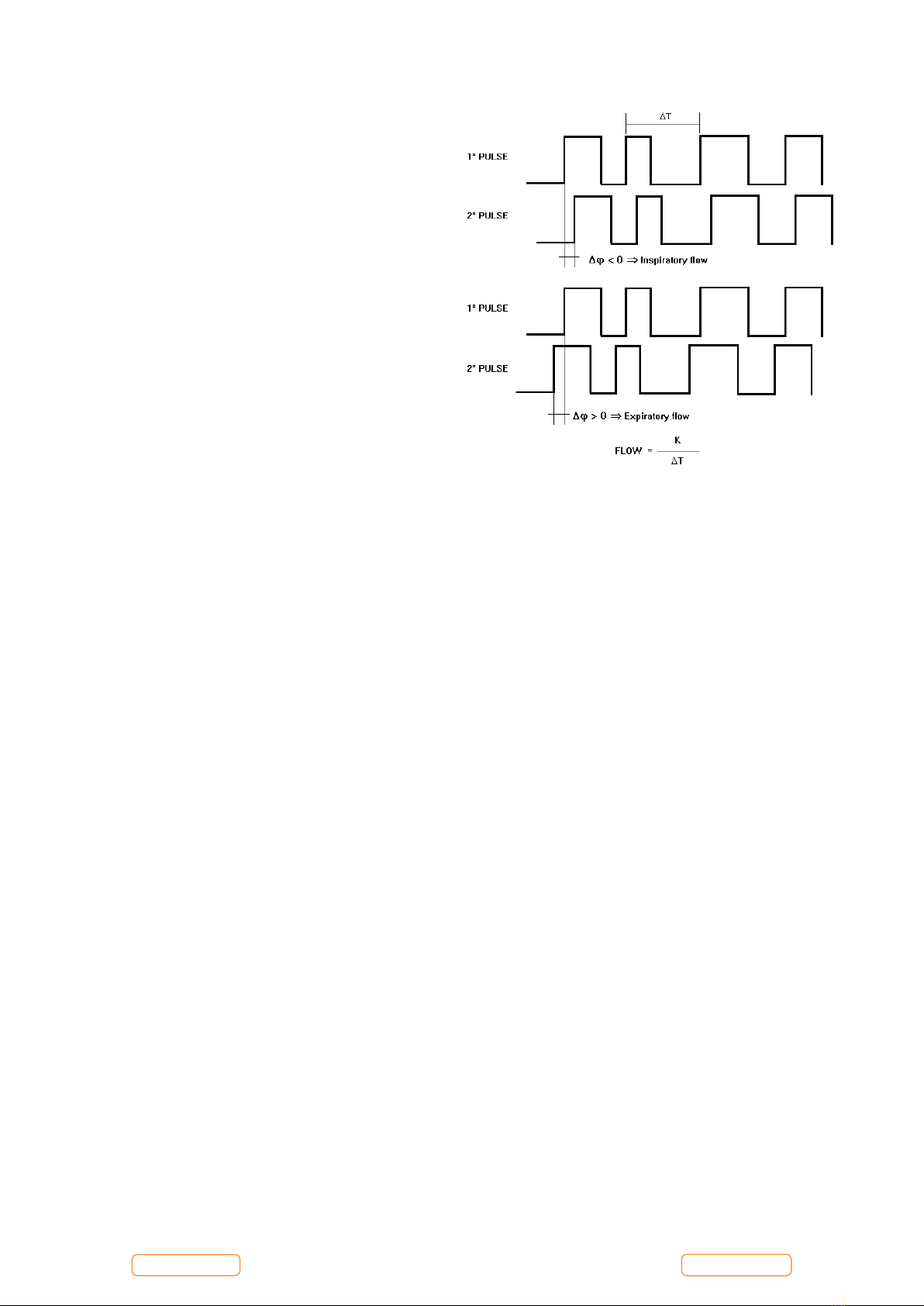
-Measuring controller for flow, volume and ambient temperature
-Ambient temperature sensor (to enable conversion from ATP to BTPS conditions).
-USB port
-Oximetry port
-Bluetooth module
-GSM Module
2.1.1. Charging controller for battery pack (IC7 LTC 4067)
The charging controlling circuit used in the new spirotel ensures a charge and optimum condition of the battery pack
providing that the battery temperature and voltage are within the preset limits. Temperature, voltage and time are all
monitored throughout the charge process.
The charging process itself is automatically initiated in two situations:
1. After connecting the battery charger to the unit.
2. When the unit is switched on, the battery charger is connected and the voltage level of the battery is below a preset
limit. In this situation the LCD indicates the low battery status with one line in the battery indicator.
The fast charging process is terminated by any of the following:
-Battery voltage out of range (Maximum/Minimum)
-Battery temperature out of range (Maximum/Minimum)
-Maximum charging time (timeout = 2h after the voltage arrives at the maximum value, 4.2 V)
Charging phases:
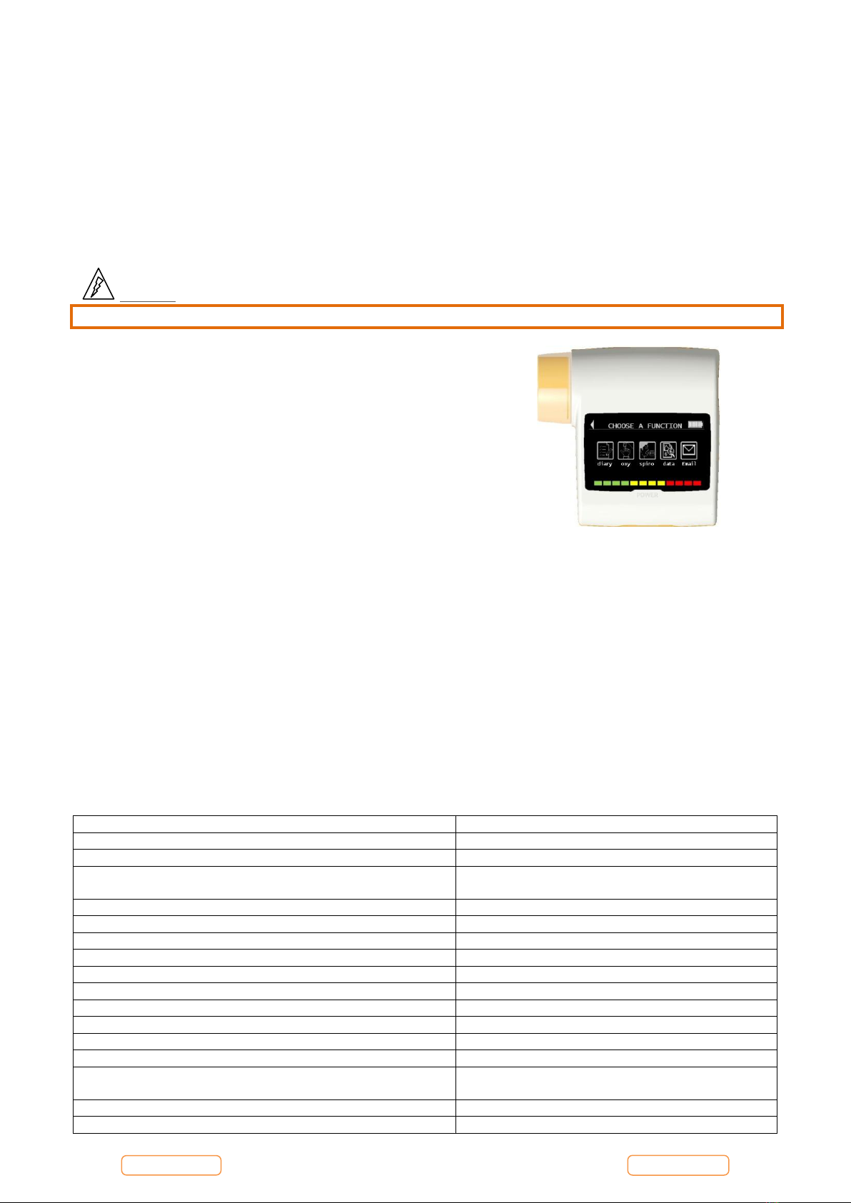
1. If everything is in order (battery temperature, temperature rising, battery voltage etc.) then the charging process starts
and the display shows the following image in the upper right
2. At the end of the regular charging process, the display shows the following message:
Battery full
3. If after completing the charging process the battery charger is still connected, a so-called Pulse-Trickle-Function is
activated that gives a very low charge to compensate the self-discharging of the battery while it is idle connected to the
charger.
2.1.2. Room temperature sensor
(IC6) DALLAS DS 18B20 to measure the ambient (room) temperature to enable the calculation of the BTPS conversion
factor.
2.1.3. USB communication port
Version 2.0.
2.1.4. Oximetry port
The connector beside the USB ports is used to connect the oximetry sensor, where this function is enabled on the device.
Many sensors can be used on new spirotel
based on the type of test to be performed and on the patient characteristics.
The manufacturer provides the most frequently used sensor with the device, which has the following features:

Page 9 of 37
Rev.1.0
Mechanical part
Finger
Electrical part
Two light emitting diodes (LEDs), one emits in the visible spectrum and one infrared
Both lights then pass through the finger and are “read” by the receiver. As these lights pass through the finger, a proportion
of the light is absorbed by the blood and by the soft tissue, in function of the concentration of haemoglobin. The quantity
of light absorbed, at each frequency, depends on the degree of oxygenation of the haemoglobin inside the soft tissue.
2.2. DISPLAY MODULE
The display module shows patient data, user set parameters and test results. The display has the touch screen function.
It is connected with:
30-pin flat-cable for digital connection, display lamp and touch controller (CON 12)
The touch controller (IC17) MAX 11800
The lamp controller (IC12) MAX 8822
2.3. TURBINE FLOWMETER
The sensor for measuring flow and volume is similar to the model already used in other spirometers produced by MIR
(Series MIR 020 rev 5 Mod. Spirobank II, MIR024_REV2 Mod. Spirobank G USB).
The turbine flowmeter consists of one mechanical and two electrical parts:
Mechanical parts:
-turbine
Electrical parts:
-Two pairs of infrared transmitters/receivers positioned as shown below.
-A signal conditioning circuit to rectify the output signal from the two infrared light receivers.
The rotation of the rotor causes the interruption of the infrared beam, thus creating a pulse signal which has a frequency
directly proportional to the flow.
The measurement of the air flow which passes through the tube is therefore proportional to the number of interruptions of
the infrared beam.

Page 10 of 37
Rev.1.0
The phase difference (positive or negative) between the
signals from each of the two infrared receivers (RX1 and
RX2) depends upon the direction of rotation of the moving
rotor and therefore supply the information of the direction
of the air flow (expiration or inspiration).
In detail, > 0 for expiratory flow, < 0 for inspiratory
flow.
The two pulse trains are squared by a Schmitt trigger
(LMV932MM on MiniFlowmeter) and then sent to two
input ports of the microprocessor (IC17 CP3BT26, pins 38
and 36).
The main microprocessor has the possibility to switch all
the peripheral ports on or off, including the turbine.
3. MAINTENANCE
3.1. GENERAL
We recommend checking the new spirotel on an annual basis.
For cleaning of the new spirotel and the accessories please see the User Manual.
3.2. TEST EQUIPMENT
For the repair and maintenance procedures of the new spirotel the following test equipment and accessories are required:
-Complete set of precision engineering tools (including 2.5 mm allen key and cross-screwdriver)
-Calibration syringe (3L is recommended)
-Case opener
-Digital multimeter, at least 3½ digits, accuracy better than 1%.
-Oscilloscope
-Digital Thermometer
-PC
-winspiroPRO Software Installation CD
-USB port connection cable
-Oximeter sensor (MIR code 919023)
-Hot Glue Gun
-3 mm double-sided adhesive tape
-Welder
-Signal cable (MIR code ZC017).
If a problem cannot be solved with the present equipment and suitable instruments are not available, please send the new
spirotel to the manufacturer to carry out the service.
3.3. CHECKLIST
The following procedures must be carried out during an inspection and/or after every repair:
Modifications, if any, must be noted on the “Service Info” sheets. See Appendix B of this manual for further
information.
Visual inspection. Check the electrical connection for safety and check that all components are properly fastened.
Check that all accessories do not present any visible damage.
Functional test (see Paragraph 3.3.1)
File a copy of all service activities.
3.3.1. Functional test

Page 11 of 37
Rev.1.0
3.3.1.1. Self test
Switch on the equipment. new spirotel will carry out the so-called self-test for approx 3 seconds. It is assumed that when
the self-test is passed all functions of new spirotel are okay.
Any severe malfunction (if any) will be reported on the display.
Switch off new spirotel.
3.3.1.2. Software version
To check the software version installed on the device, switch on new spirotel
pressing and releasing the power key placed in the middle on the side of the
device, wait for the first screen to appear; the software version is found as
indicated in the image alongside.
4. REPLACEMENT PROCEDURES
4.1. General
When handling sensitive static devices such as the motherboard of the new spirotel the following precautions should be
observed:
-Persons should be earthed by means of a wrist strap.
-Ground all electrical equipment, workbench etc.
Also make sure that you have not left any tools inside and all screws including their washers are again fixed in the original
place.
Note
Where not otherwise indicated, the reinstallation of a part is in reverse order of the removal procedure.
After every repair a functional test must be performed.
Caution
If any soldering (especially on SMD-parts) is to be made, make sure that your tools are suitable for such precision
work.
4.2. Cover
The new spirotel case consists of several parts as illustrated
in the image to the right.
The components are housed inside its casing which is made
up of three main case parts held together with two screws.

Page 12 of 37
Rev.1.0
4.2.1. Opening the device
To open new spirotel:
1. Switch off the device and make sure that the turbine housing is removed from the main body of the device.
2. Place the device on a flat surface with bottom part face-up
3. Remove the battery compartment cover and using the case
opener, move all around the perimeter to release the clips
and pry the backing. Pay attention to not damage the plastic
material.
4. Remove the battery pack from it’s compartment leaving the
connection intact.
5. Completely remove the two screws using a screwdriver
3
4
5
6. Remove the lower case using the same method for the battery compartment side using the case opener to pry between
the orange and white pieces. Pay attention to not damage the plastic material.
6
Caution
Pay attention to the display flat cables connected to the main PCB and passing through the orange case
component.
7. The PCB now is only inserted in the middle case (orange). To remove the PCB, take the PCB with both hands and
separate the case from the PCB.

Page 13 of 37
Rev.1.0
Caution
During this phase be careful to not break the elements shown above when prying the case apart.
4.3. PCBs and components
4.3.1. Removing and replacing the turbine sensor strip
1. Open new spirotel as described in 4.2.1.
2. With the device face down, locate where the sensor strip is
connected to the PCB.
3. Using a screwdriver or case opener, carefully pry the clear plastic
clip from the centre underneath. Be careful as the clip may pop
out rapidly.
4. With the clip removed, carefully remove the first diode by prying
the strip directly out of the hole. Once the diode is removed,
unclip the strip from the PCB. Gently turn over the PCB to keep
it out of the way, making sure not to damage the flat display
connector.
5. Remove the clear plastic clip on the opposite side of the housing
as performed in step 2.
6. Remove the second diode from its hole
as performed in step 3.
7. Slide the strip out the hole at the top as
shown in the image to the right.
8. The third plastic clip connected to the
two receivers can then be removed.

Page 14 of 37
Rev.1.0
4.3.2. Removing and replacing the display
1. Open new spirotel as described in Paragraph 4.2.1; once the PCB is
separated from the sensor strip (as described in 4.3.1, and removed from
the yellow casing, unclip the flat cable and remove the display.
2. Then apply a new display in the correct position on the yellow casing.
Ensure the display tabs align in the correct holes as shown in the image
below.
3. Connect the single flat cable of the display to the PCB. After the connector is inserted, secure it by closing the brown
wings to lock in the connector. Do not apply an excessive bend to the flat connectors of the display near to the
connector, as this could cause breakage or malfunction.
4. At this time, it is possible to close the device following the instruction described in 4.2.1 in reverse order.
4.3.3. Touch Screen Calibration
This function is used to check the proper response of the touch screen; the device initially requests a confirmation, touching
the OK icon begins calibration.
There are four phases as follows:
Touch the top left-hand point of the display three times
Touch the top right-hand point three times
Touch the bottom right hand point three times
The reference area is the one inside the flashing outline.
This procedure must be carried out using the tip of a touch-screen “pointer” held vertically at 90 degrees to the display.
If the calibration is made correctly then the device shows:
Calibration is OK
Otherwise, the user is requested to repeat the calibration procedure.
The procedure cannot be cancelled once started, so the user must carry perform the procedure correctly to return to the
service menu.
In event the touch screen doesn’t work correctly, it is possible to follow the following procedure to reset this function:

Page 15 of 37
Rev.1.0
Switch off the device pressing the ON/OFF key until the device is switched off.
Now, open the device as described in point 4.2.1 in order to remove the battery
pack.
Press the ON/OFF key 3 or 4 times to discharge capacitors.
Re-connect the battery pack.
Close and switch on the device.
The first display will appear as the screen on the right.
Touch the icon “touch calibration” at the top of the display and follow the
directions; the procedure is the same described above.
4.3.4. Removing and replacing the internal battery pack
1. Open new spirotel as described in Paragraph 4.2.1 up to point 3.
2. Remove the battery pack, only after the device is switched off, by withdrawing the connector using a screwdriver or a
tweezers.
3. Replace the battery with a new one.
Caution
Insert the connector in the correct position all the way. Do not force the connector.
Place the cable of the battery oriented as shown in the image above; the cable must be between the battery and the
upper casing.
Warning
Handle battery pack with care. Contact between battery terminals with the circuit board can cause permanent
damage to the circuit board itself.
4. Close the device as described in point 4.2.1.
Caution
When inserting the battery cover, do not crush the battery cable.
Note:
Batteries must be disposed of properly, according to local regulations.
WARNING
Use only battery packs supplied by MIR
Improper use of the battery pack may cause acid leakage, overheating, smoke, breakage, an explosion and/or fire.
Consequently the battery pack may be damaged or suffer a drop in overall performance. The internal battery pack

Page 16 of 37
Rev.1.0
safety sensor could also be damaged as well by any of the above events. Furthermore the user of the device could
be harmed and other nearby appliances could be damaged as well.
Please read the following instructions carefully.
DANGER
Do not disassemble or modify the battery pack. The battery pack comes with an internal safety sensor; which if
tampered with may cause acid leakage, overheating, smoke, breakage, an explosion and/or fire.
Do not short-circuit the positive(+) and negative (-) terminals with any metal objects.
Do not carry the battery pack in your pocket or in a bag with other metallic objects like necklaces, hairpins, coins
or screws.
Do not store the battery pack near any such objects.
Do not warm-up or throw the battery pack in a fire.
Do not use or store the battery pack near a fire or in a vehicle where the temperature may reach 60°C or higher
Do not immerse the battery pack in water or salt-water, and do not get it wet.
Such events may damage the internal battery safety sensor, thus causing the battery to be charged at a higher
voltage, triggering abnormal chemical reactions leading to acid leakage, overheating, smoke, an explosion and/or
fire
Do not charge the battery pack near a fire or in an extremely hot environment. High temperature may activate the
internal battery safety sensor thus inhibiting the charge. The high temperature may also damage the internal
battery safety sensor causing extremely high current surge; and consequently causing abnormal chemical
reactions in the battery pack triggering acid leakage, overheating, smoke breakage, an explosion and/or fire.
Use only the battery charger supplied by MIR to recharge the battery pack. Recharging with an unsuitable charger
in nonconforming conditions may cause the battery pack to overcharge or the charging current to be extremely
high thus causing abnormal chemical reactions in the battery pack triggering acid leakage, overheating, smoke
breakage an explosion and/or fire.
Do not puncture the battery pack with sharp objects such as a nail.
Do not hammer, step-on, throw or cause a forceful impact to the battery-pack.
A damaged or deformed battery pack may cause internal short-circuits thus creating the possibility for acid
leakage, overheating, smoke, breakage and/or fire.
Do not use a heavily scratched or deformed battery back as this may be cause for acid leakage, overheating,
smoke, breakage and/or fire.
Do not solder directly on the battery pack.
Do not mount the battery pack inside the device with the + and –terminals inverted.
If the battery leads do not connect easily to the battery charger or to the device, do not apply excessive force.
Check to see that the leads are properly aligned. If the leads are inverted, an inverse polarity connection may
provoke acid leakage, overheating, smoke, breakage and/or fire.
Do not connect the battery pack leads to a wall socket or to the car lighter. Under high voltage the battery may
leak acid, overheat, emit smoke, explode and/or catch fire.
Do not use the battery pack for any other purpose other than those specified otherwise its features may be
compromised, and its useful life reduced.
If the battery acid inadvertently enters the eyes do not rub the eyes, instead wash the eyes with clean running water
and call a doctor immediately.
WARNING
Do not leave the battery pack charging longer than the average charging length of time specified.
Do not place the battery in a micro-wave oven or in a pressurized container. Rapid overheating or loss of proofing
may cause acid leakage, overheating, smoke, breakage and/or fire.

Page 17 of 37
Rev.1.0
If the battery pack gives off a bad smell, if it generates heat, if it fades/deforms or if anything abnormal happens
during storage, usage and recharging immediately remove the battery pack from the device or the battery charger
and do not use it any longer, as any of these events may cause acid leakage, overheating, smoke, breakage and/or
fire.
NOTE
The battery pack includes an internal safety protector. Do not use the battery pack where static electricity is
present(higher than what is declared by the manufacturer).
If acid from the battery pack comes into contact with skin or clothing immediately wash with running water to
avoid skin inflammation.
Store the battery pack away from children’s reach to avoid any accidental swallowing.
If a child uses the battery pack an adult must explain the proper use to the child.
Before using the battery pack, read the manual carefully paying attention to all the recommendations for proper
handling.
Please read the manual carefully to insert and remove of the battery pack in the device properly.
Before charging the battery pack, read the manual carefully.
The battery pack life cycle is definite. If you notice a much shorter time usage between charges please substitute
the battery pack with a new one.
Remove the battery pack if its cycle life has expired.
When the battery pack has been removed from the device, ensure that the (+) and (-) leads have been isolated with
electrical tape; to properly dispose of the battery pack please follow the local regulations or hand over the battery
pack to a battery recycling centre.
Prior to storage or for long periods of disuse of the device, remove the battery pack and store in a place where the
temperature and humidity fall within specified ranges.
If the battery pack leads are dirty clean with a dry cloth prior to usage.
The battery pack can be charged within a temperature range between 0°C and approximately 40°C
The battery pack may be used within a temperature range between -20°C and approximately 60°C.
The battery pack may be stored within a temperature range between -20°C and approximately 60°C.
4.3.5. Turbine
Re-usable turbine
WARNING
The correct use of a “re-usable” turbine is guaranteed only and exclusively if it is
“clean” and free from foreign bodies that alter the motion of the blades. If a re-
usable turbine can is not properly cleaned, it can cause cross infection between
patients. Periodical cleaning of the device is sufficient only if that device is used
exclusively by the same patient. For further details about cleaning, refer to the
appropriate section in this User Manual.
Never expose turbine sensors to jets of water or air or allow contact with hot liquids.
To avoid malfunctions or damage, do not introduce dust or foreign bodies into the turbine sensor. The presence of foreign
bodies (such as bodily hair, hair, saliva etc.) inside the turbine flow meter can compromise the accuracy of readings.
4.3.5.1. Cleaning the reusable turbine
Turbine operation check:
Turn on new spirotel and setup the device to perform a spirometry test (for example FVC).
Hold the new spirotel with one hand and move it slowly sideways, having the air pass through the turbine.
If the rotor spins properly the device will emit a series of acoustic signals “beeps”. The beeping frequency is a function
of the air flow passing through the turbine.
If no beeps are heard while moving the device, proceed to clean the turbine
CAUTION

Page 18 of 37
Rev.1.0
Periodically check the inside of the turbine to ensure that there are no impurities, corpuscles, or any foreign matter
like hairs which could inadvertently block or even slow down the mobile equipment in the turbine and as a
consequence compromise spirometry measurement accuracy.
To clean the reusable turbine, first remove it by pulling it gently from the new spirotel turning it anti-clockwise and
pressing lightly. It can be helpful to push it gently from underneath with one finger from the bottom of the turbine to lift it
out of its housing.
Immerse the turbine in a cold liquid solution and move it within the liquid to remove any impurities which may be deposited
inside. Leave the turbine immersed for the time specified in the instruction of the solution.
Rinse the turbine by immerging it in clean water (not hot).
Shake off the excess water from the turbine and leave it to dry, standing it vertically on a dry surface.
To ensure that the turbine is functioning correctly before replacing it inside the instrument, it is good practice to make a
visual check of the rotation blade. Placing the turbine tube horizontally and moving it gently from left to right and vice
versa, the rotation blade (rotor) must rotate freely. Otherwise, accurate measurement is no longer guaranteed and the
turbine must be replaced.
Once the turbine has been cleaned insert the turbine tube in its place following the instructions indicated by the closed lock
symbol printed on the plastic casing of the new spirotel.
To insert the turbine correctly push it and then turn it clockwise until it reaches the stop, which ensures that the tube has
been blocked inside the casing.
4.3.5.2. Calibration of the reusable turbine
Only reusable turbines can be calibrated.
See instructions in the Calibration section of the User Manual of the device.
The turbines used on new spirotel do not require periodic calibration as they are already calibrated.
4.3.6. Internal software upgrade procedure
In order to upgrade the software winspiroPRO must already be installed and the PC must have an internet connection for
downloading the upgrades and firmware of the new spirotel from www.spirometry.com.
Launch winspiroPRO on the PC and connect new spirotel
to the PC using the micro USB cable.
winspiroPRO can check the correct functioning of the USB port from the “options” menu; before downloading any newer
releases, make sure that the device is correctly connected to the PC software, the software will automatically recognize the
device if it has already been connected to the PC and then carry out the following instructions. To check the connection
between the device and the PC, go to the “Configuration -> Options... -> Communication” menu. Click ‘TEST USB.’ The
screen will appear as below if the test is successful:
External control
USB

Page 19 of 37
Rev.1.0
To download the new internal software
version click on "Tools" menu, and then on
"Upgrade Device Internal Software"
This wizard helps the user to select the method used to connect
the device to the PC and then, with the “TEST” icon, the user
can check the connection (see image).
Search for the .tsk file to be downloaded into the spirometer.
Choose either auto-install or manual file search; browse system
resources through list of folders, select .tsk file and then click on
Next.
From the “Select file .tsk” search window select the firmware of
your device; click on the new spirotel folder and then on the
selected file to automatically launch the upgrading procedure of
the internal software of the spirometer.
4.4. Oximeter module
To check the oximeter module used on the device, refer to Annex
4.
CAUTION
Make sure before operating on the oximetry module to
switch off the device or disconnect the battery charger.
4.4.1. Replacing of the oximetry module

Page 20 of 37
Rev.1.0
Open the device as described in point 4.2.1 up to point 6.
Beneath the Bluetooth module, the oximetery module is
connected directly to the PCB.
Remove the oximetry module by hand, gripping the sides
and pulling directly away from the board.
CAUTION
The module is attached to the PCB so it must be
removed gently.
Replace the oximetry module.
To attach the oximetry module to the PCB, it is recommended to apply an adhesive in the space between the PCB and the
highest micro on the oximetry module (placed in the face not visible).
Close the device as in point 4.2.1 in reverse order.
4.5. Testing procedures
After making all repairs described in the previous paragraphs, correct functioning tests must be performed on both the
Hardware and Software.
Devices with oximeter and devices without oximeter have their own specific testing procedures.
4.5.1. Testing procedures for devices with oximeter
The following checks must be carried out on each device:
Other manuals for Spirotel
1
Table of contents
Other MIR Medical Equipment manuals

MIR
MIR Spirobank II User manual

MIR
MIR Spirolab User manual

MIR
MIR Spirobank Smart User manual

MIR
MIR MIROxi User manual

MIR
MIR MiniSpir Light User manual

MIR
MIR Spirolab New User manual

MIR
MIR Smart One User manual

MIR
MIR Smart One Oxi User manual

MIR
MIR Minispir New User manual

MIR
MIR SPIROBANK Oxi User manual
Popular Medical Equipment manuals by other brands

Canon
Canon Omnera 500A Operator's manual

Direct Supply
Direct Supply Bolster owner's manual

Cirs
Cirs Dynamic Phantoms 008A user guide

Hollister
Hollister Apogee HC Guide for Use

Getinge
Getinge Arjohuntleigh Nimbus 3 Professional Quick reference guide

Stryker Medical
Stryker Medical RUGGED 6080 MX-PRO Operation & maintenance manual