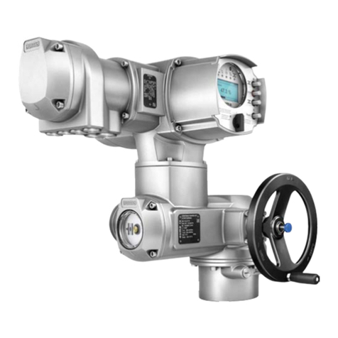
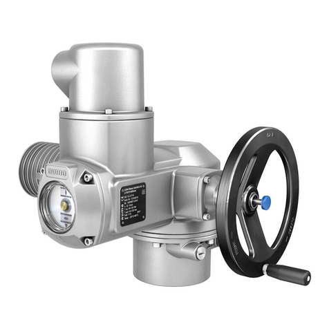
AUMA PROFOX PF-M25 Manual

PROFOX actuators
PF-M25(X) –PF-M100(X)
PF-Q80(X) –PF-Q600(X)
Profinet
Use short instructions in combination with operation instructions only!
These short instructions are only complete with the respective operation instructions of the
actuator.Safety and warning instructions contained in the actuator operation instructions must
be heeded when performing work on the actuator!
Fieldbus connectionShort instructions

Table of contents Page
31. Basic information to fieldbus and network connection......................................................
52. Cable connection...................................................................................................................
93. Connect network cables........................................................................................................
124. Parameters (Profinet).............................................................................................................
135. Technical data......................................................................................................................... 135.1. Profinet interface
2
Table of contents

1. Basic information to fieldbus and network connection
Electrical connection The actuator cover must be opened to allow connection of the network cables.
Refer to actuator operation instructions, “Electrical connection”chapter.
The “Electrical connection”chapter of the operation instructions fully applies
to the connection of the fieldbus and network cables. It is imperative to heed
the safety and warning instructions of this chapter in particular.
Profinet cables The following minimum requirements with regard to LAN cables apply for Profinet
networks: Category 5 according to ISO/IEC 11801 Edition 2.0 Class D.
Connector is suitable for wiring dual pair Profinet cables.
The following tables list the available cable types Profinet types A through C with
regard to the respective application:
Table 1:
Cable types for dual pair Profinet cables
Application type CApplication type BApplication type ACable types
Dual pair data cableDual pair data cableDual pair data cableVersion
special applications (e.g.for contin-
ous movement, vibration or twist-
ing)
flexible installation (e.g.for contin-
ous movement, vibration or twist-
ing after installation)
fixed installation, immobile after
installation
Type of installation
Cable parameter
“PROFINET type C”“PROFINET type B”“PROFINET type A”Designation (minimum)
AWG 22/.. ≥0.318 mm²AWG 22/7 ≥0.318 mm²AWG 22/1 ≥0.610 mm²Cross section
depending on application5.5 –8.0 mmOuter cable diameter
depending on application1.4 ±0.2 mmWire diameter
depending on applicationGreen RAL6018Colour of shield
Pair 1: white, blue
Pair 2: yellow, orange
Colour of wire insulation
4Number of wires
Dual pair or star quadCable design
depending on applicationAlumium foil + copper braidShield
Communication requirements
ISO/IEC 11801 Edition 2.0
IEC 61140-1
IEC 61156-6
(minimum device group 5)
ISO/IEC 11801 Edition 2.0
IEC 61140-1
IEC 61156-5
(minimum device group 5)
Applicable standards
≦20 ns/100 mDelay
≥80 dB at 30 –100 MHz
“Channel class-D”according to EN 50174-2
Coupling attenuation
Minimum cable spacing The minimum spacing (according to IEC 61918) required between laying Profinet
cables and other cables must be respected.They are shown in the table below.
3
Basic information to fieldbus and network connection

Table 2:
Minimum spacing for Profinet cables
Spacing to Profinet cable
Steel cutoff bridgeAluminium cutoff bridgeWithout or with non-metal
cutoff bridge
Signal transmission cables
0 mm0 mm0 mmE.g. other Profinet cables, Profibus cables, data cables
forPCs,programming devices,shielded analogue inputs
Power supply cables
50 mm100 mm200 mmUnshielded power supply cables
0 mm0 mm0 mmShielded power cables
Further references Ensure absence of equipotential earth bonding differences between the individual
devices at Profinet (perform an equipotential earth bonding).
Available Profinet recommendations, particularly planning, assembly and
commissioning guidelines of the Profibus User Organisation (PNO)
(www.profibus.com) must be met.
4
Basic information to fieldbus and network connection

2. Cable connection
Cable arrangement
Cable arrangement depends on the number of cables connected in addition to the
mains cable.There are two options:
Figure 1: Cable arrangement
[1] Cable arrangement for a mains cable and a fieldbus or a network cable
[2] Cable arrangement for a mains cable, a fieldbus or a network cable and a
signal cable
For better accessibility, we recommend heeding the following order.
1. If a signal cable is connected in addition to the fieldbus or network cable:Insert
signal cable into cable gland on the right and push upward until the cable is
visible.
2. Insert fieldbus or network cable into middle cable gland and push upward until
the cable is visible.
3. Insert mains cable into cable gland on the left and also push upward until the
cable is visible.
4. Remove cable sheathing.
5. Strip wires.
→Controls approx. 6 mm, power supply unit approx. 10 mm
6. For flexible cables:Use wire end sleeves according to DIN 46228.
5
Cable connection

Protective earth connection
In case of a fault, electric shock due to presence of hazardous voltage if the
PE conductor is NOT connected!
Risk of death or serious injury!
→Connect all protective earth conductors.
→Connect PE connection to external protective earth conductor of connecting
cables.
→Start running the device only after having connected the protective earth con-
ductor.
7. Fasten PE using spade lugs or wire end sleeves at protective earth connection
( ) as shown.Do not completely loosen screw!
Figure 2: Protective earth connection (standard version)
Figure 3: Protective earth connection (explosion-proof version)
Information For actuators in explosion-proof version, the PE conductor must be attached between
the U-bracket and the metal washer resting on the housing.
Table 3:
Terminal cross sections and tightening torques of PE connection
Tightening torquesTerminal cross sectionsDesignation
3 –4 NmAll versions:
1.5 –2.5 mm2(flexible) directly
Standard version:
1.0 –6 mm2(flexible) via spade log or wire end
sleeve
1.5 –6 mm2(solid) direct
Explosion-proof version:
1.0 –2.5 mm2(flexible) via spade log or wire end
sleeve
1.5 –2.5 mm2(solid) direct
Protective earth connection
(PE)
6
Cable connection

Connection of mains and signal cables
8. Connect mains cable according to order-related wiring diagram.
Table 4:
Terminal cross sections
Cross sectionWire typeDesignation
max [mm²]min [mm²]
2.50.08rigid/flexibleMains cable
AWG 12AWG 28AWG
9. Connect signal cables in push-in technology according to order-related wiring
diagram.
Information: Only required if a signal cable is to be connected in addition to
the fieldbus or network cable.
Damage to push-in terminals by jamming of wire end sleeves with the housing!
Replacement of the complete component is required.
→Use wire end sleeves with smooth surface.
→Always press the push-in terminals completely down using a screwdriver and
always carefully remove signal cables.
→It must be possible to pull out the signal cable without resistance when the push-
in terminal held down.
Information: To avoid unevenness at wire end sleeve, AUMA recommends
using the Crimpfox 6 model by Phoenix Contact as suitable crimping pliers.
Figure 4: Connect signal cables
Table 5:
Terminal cross sections
Cross sectionWire typeDesignation
max [mm²]min [mm²]
1.50.2solidI/O signal cable
1.50.2flexible
1.50.2flexible with wire end
sleeve without plastic
sleeve
AWG 16AWG 24AWG
7
Cable connection

10. Connect fieldbus or network cables.
Refer to subsequent chapter!
8
Cable connection

3. Connect network cables
When connecting network cables, attention must be paid to the specialities of the
deployed topology.
When setting the cycle rate or the watchdog within Profinet controller, the delay times
which result from the selected topology must be considered.
Figure 5: Point-to-point or star topology
Figure 6: Ring topology
Information If a PROFOX actuator is part of a complete ring topology, the connection to other
participants within the ring remains even if the actuator is not supplied or defective.
However, the ring is then interrupted and a fault of a further ring participant leads to
connection loss.
Figure 7: Line topology
Information For Profinet, line topology is not recommended. If one participant fails, the other
participants along the line are no longer accessible.Therefore, it is advised to use
ring topology instead.
SignificationSymbol
from the previous device↑
to the next device↓
9
Connect network cables

In case of a fault, electric shock due to presence of hazardous voltage if the
PE conductor is NOT connected!
Risk of death or serious injury!
→Connect all protective earth conductors.
→Connect PE connection to external protective earth conductor of connecting
cables.
→Start running the device only after having connected the protective earth con-
ductor.
1. Strip network cables.
Shield connection 2. Remove network cable shield at a short section as shown and connect to shield
connection. Ensure absence of electrical contact to the terminal.
Information: If the cables are too thin to be clamped, fold over the shielding
and clamp it underneath.
Information: Strain relieve must always be made via cable glands.For this,
the shielding connection may not be used.
Figure 8: Shield connection
Information Stripped cables should be exposed for as short as possible.If possible, leave the
wires twisted until just before the terminal or do not untwist them.
10
Connect network cables

Network cable 3. Connect network cables:Profinet connection is made individually by means of
a safe Ethernet-capable push-in terminal.The colour coding of connection ter-
minals are matching the Ethernet cable according to Profinet (white/blue/yel-
low/orange).
Table 6:
Terminal cross sections
Cross sectionWire typeDesignation
max. [mm²]min. [mm²]
1.50.5solidFieldbus cables
1.50.5flexible
1.00.5flexible with wire end
sleeve without plastic
sleeve
AWG 16AWG 20AWG
Table 7:
Connection terminal assignment
Colour of wire insulationFunctionSignal
YellowTransmit Data +TD +
OrangeTransmit Data –TD –
WhiteReceive Data +RD +
BlueReceive Data –RD –
4. If the PE conductor has been removed from the cover, it must be tightened
applying 2.2 Nm tightening torque prior to re-placing the cover.
5. Fasten cable glands with the torque as specified by the manufacturer to ensure
respect of required enclosure protection.
6. Connect power supply.
If the end position setting is carried out with the internal operation buttons
following the connection to the power supply: Do not close cover!
11
Connect network cables

4. Parameters (Profinet)
Signals
Feedback signals via Profinet can be configured using the engineering tool of the
DCS/PLC and the GSD file of actuator (available for download at www.auma.com).
Refer to Manual PROFOX “Device integration Profinet”for information on control
commands and feedback signals via Profinet”.
Change-over between Profinet control and OPEN-CLOSE via I/O signals
As standard, the actuator is supplied with Profinet interface and digital inputs.A
digital input is used to define which source is active, this means whether the actuator
is controlled via Profinet or via I/O signals.It is not possible to use both sources to
active simultaneously.The PRM_926 Signal DIN 3 signal is assigned to PZD_275
I/O interface as factory setting:
Not live (= 0V) means that control is made from REMOTE via Profinet.
Live (= 24V) means that control is made from REMOTE via binary I/O signals.
Commands for the operation function:
OPEN-CLOSE operation commands can be issued via Profinet or a setpoint can be
sent for any position.Change-over is made via the commandPZD_332Fieldbus
SETPOINT.
●Setpoint control:
Fieldbus SETPOINT command bit = 1 = REMOTE SETPOINT
The actuator reacts to the setpoint E1 transmitted via Profinet.
●OPEN-CLOSE control:
Fieldbus SETPOINT command bit = 0 = REMOTE OPEN-CLOSE
Actuator can be operated via Fieldbus OPEN/Fieldbus CLOSE command bits
in direction OPEN or CLOSE.
For further information on these parameters as well as on other settings,refer
to the Manual PROFOX “Parameters and functions”.
12
Parameters (Profinet)

5. Technical data
Information The following tables include standard and optional features.For detailed information
on the customer-specific version, refer to the order-related data sheet.The technical
data sheet can be downloaded from the Internet in both German and English at ht-
tp://www.auma.com (please state the order number).
5.1. Profinet interface
Settings/programming the Profinet interface
The Profinet interface is set (assignment of device name as well as assignment of the IP address) using the Profinet engineering tool of the
DCS.
General data of the Profinet interface
Profinet according to IEC 61158 and IEC 61784Communication protocol
Star topology, point-to-point wiring
Due to the integrated switch function, both line topologies and redundant ring topologies (MRP) are
available.
Network topology
Ethernet IEEE 802.3
2-pair cabling in compliance with IEC 61784-5-3 Auto Polarity Exchange, Auto Negotiation and Auto
Crossover are supported.
Connection
2 x Ethernet connection terminals, integral screen with strain relief, suitable for all Ethernet cable typesProfinet connection
100 Mbits/s (100BASE-TX), full duplexTransmission rate
Max. 100 mCable length
I/O controller (typically the PLC/DCS)
I/O devices (field devices)
I/O supervisor (programming device, PC or HMI for diagnostics/commissioning)
Device classes
Provider - consumer modelCommunication model
Version V2.32Supported Profinet specification
Cyclic Profinet communication (RT)
Acyclic Profinet communication (Read/Write Record)
Supported Profinet functions
Status Alarm
Update Alarm
Port Data Change Notification Alarm
Sync Data Change Notification Alarm
Supported Profinet alarms
ACD (Address Conflict Detection)
ARP (Address Resolution Protocol)
DCP (Discovery and Basic Configuration Protocol)
SNMP (Simple Network Management Protocol)
LLDP (Link Layer Discovery Protocol) in accordance with IEEE 802.1AB
These functions allow assignment of the Profinet device name, a graphic representation of the plant to-
pology, port-granular diagnostics as well as neighbourhood detection as the basis for quick commissioning
and easy device replacement.
Supported network diagnostic and
management protocols
(Media Redundancy Protocol) in compliance with IEC 62439 (switch function integrated in
PROFOX)
Standard:Profinet redundancy
System redundancy S2 Single NAPOption:
319Vendor ID
14Ident code
AUMA PROFOXProfinet device type
62976I&M0 Profile ID:
4I&M0 Profile Specification Type:
257I&M0 Version:
30I&M0 Supported:
Identification&Maintenance proper-
ties
0x013F; 0x000EProfinet Ident Nr.
0x80010000DAP (Device Access Point)
13
Technical data

General data of the Profinet interface
CC-B (Conformance Class B) for the Profinet application of PROFOX
CC-C (Conformance Class C) for the integral switch function
Conformance class
IIINetload Class
Via TCP/IP and integral web server possible
Via FDI package & software for diagnostics/commissioning (e.g. Siemens PDM, Emerson AMS, ABB
FIM)
Device diagnostics via Ethernet
Via GSD (ml) file (available for download at www.auma.com)Device integration
Commands and signals of the Profinet interface
OPEN, STOP, CLOSE, position setpoint, RESET, EMERGENCY operation command, OPEN/CLOSE,
start torque comparative operation
Process representation output
(command signals)
End positions OPEN, CLOSED
Actual position value
Actual torque value
Selector in position LOCAL/REMOTE/OFF
Running indication (directional)
Torque switches OPEN, CLOSE
Limit switches OPEN, CLOSED
Analogue (1) and digital (3) customer inputs
Process representation input
(feedback signals)
Thermal fault
Torque fault CLOSE and OPEN
Failure of analogue customer inputs
Process representation input
(fault signals)
The behaviour of the actuator is programmable:
●Stop in current position
●Travel to end position OPEN or CLOSED
●Travel to any intermediate position
●Execute last received operation command
Behaviouron lossof communication
14
Technical data

15

AUMA Riester GmbH & Co. KG
P.O. Box 1362
DE 79373 Muellheim
Tel +49 7631 809 - 0
Fax +49 7631 809 - 1250
www.auma.com
Y009.579/003/en/1.22
For detailed information on AUMA products, refer to the Internet: www.auma.com
Other manuals for PROFOX PF-M25
2
This manual suits for next models
7
Table of contents
Other AUMA Controllers manuals
