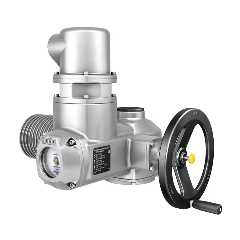
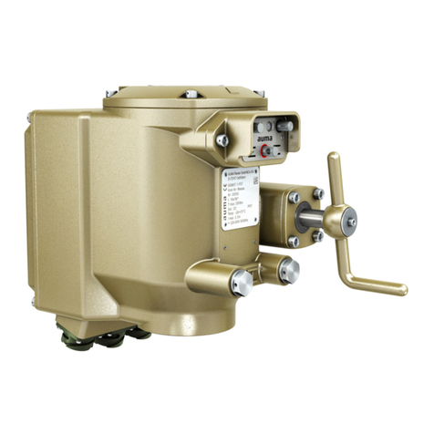
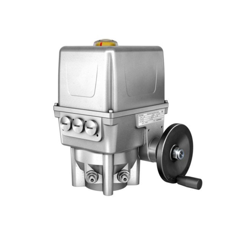
AUMA FQM 05.1 User manual

FQM 05.1 –FQM 12.1 /FQMEx 05.1 –FQMEx 12.1
with non safety-related actuators
SQ 05.2 –SQ 12.2/SQR 05.2 –SQR 12.2
SQEx 05.2 –SQEx 12.2/SQREx 05.2 –SQREx 12.2
with actuator controls
AC 01.2/ACExC 01.2
Functional safetyManual

NOTICE for use!
This document is only valid with the latest operation instructions attached to the device, the attached manual as
well as the respectively pertaining technical and electrical data sheets.They are understood as reference
documents.
Purpose of the document:
The present document informs about the actions required for using the device in safety-related systems in
accordance with IEC 61508 or IEC 61511.
The safety manual is primarily intended for consultants, operators, service staff and managers setting up, operating
or maintaining safety instrumented systems (SIS) equipped with FQM / FQMEx fail safe unit.Together with the
reference documents, the present safety manual provides all information required for safe SIS integration,
operation and maintenance of the FQM / FQMEx fail safe unit.
Reference documents:
●Operation instructions (Assembly, operation, commissioning) for actuator.
●Operation instructions (Assembly, operation, commissioning) Fail safe unit.
●Manual (Operation and setting) AC 01.2/ACExC 01.2 actuator controls.
●Manual (Device integration Fieldbus) AC 01.2/ACExC 01.2 actuator controls.
●Technical data referring to the fail safe unit, the actuator and actuator controls.
●Declaration of incorporation and EU declaration of conformity for the fail safe unit.
●SIL Declaration of Conformity on functional safety (order related)
Reference documents are available on the Internet at: http:\\www.auma.com.
Table of contents Page
41. Terminology............................................................................................................................ 41.1. Abbreviations and concepts
62. Application and validity......................................................................................................... 62.1. Range of application 62.2. Standards 62.3. Valid device types
83. Architecture, configuration and applications...................................................................... 83.1. Architecture (actuator sizing) 83.2. Configuration (setting)/version 103.3. Further notes and indications on architecture 103.4. Applications (environmental conditions)
114. Safety instrumented system and safety functions............................................................. 114.1. Safety instrumented system including an actuator 114.2. Safety functions 124.3. Safe inputs and outputs 134.4. Redundant system architecture 144.5. Application example 144.6. System representation 144.7. Diagnostic function by the operator 154.8. Internal diagnostics of fail safe unit
165. Installation, commissioning and operation......................................................................... 165.1. Installation 185.2. Commissioning
2
Table of contents with non safety-related actuators

185.3. Operation 185.4. Lifetime 195.5. Decommissioning 195.6. Disposal and recycling
206. Indications..............................................................................................................................
217. Signals..................................................................................................................................... 217.1. Signals via FS module 217.2. Status signals via output contacts (digital outputs) of actuator controls 217.3. Signals via fieldbus of actuator controls
228. Tests and maintenance.......................................................................................................... 228.1. Safety equipment: check 228.2. Internal actuator monitoring with control via actuator controls 238.3. Execute PartialValve StrokeTest (PVST) 248.4. Proof test (verification of safe actuator function) 248.4.1. Check ESD operation (Safe OPENING/CLOSING) 258.4.2. Check ESD operation (Safe OPENING/CLOSING) with additional tripping in case of
mains failure 268.4.3. Check safe end position signal 278.4.4. Test counter of FQM diagnostic operations within the AC .2 actuator controls 278.5. Maintenance
299. Safety-related figures............................................................................................................. 299.1. Determination of the figures 299.2. Specific figures for fail safe unit in SIL version with actuators of SQ .2 series
3310. Checklists............................................................................................................................... 3310.1. Commissioning checklist 3310.2. Proof test checklists 3310.2.1. Safe ESD safety operation (Safe OPENING/CLOSING) 3410.2.2. Review and validation of the “Safe end position feedback”safety function 3610.2.3. FQM diagnostic operation counter checklist
3711. SIL Declaration of Conformity (example).............................................................................
43Index........................................................................................................................................
3
with non safety-related actuators Table of contents

1. Terminology
Information sources ●IEC 61508-4, Functional safety of electrical/electronic/programmable electronic
safety-related systems –Part 4: Definitions and abbreviations
●IEC 61511-1, Functional safety - Safety instrumented systems for the process
industry sector –Part 1:Framework, definitions, system, hardware and software
requirements
1.1. Abbreviations and concepts
To evaluate safety functions, the lambda values or the PFD value (Probability of
Dangerous Failure on Demand) and the SFF value (Safe Failure Fraction) are the
main requirements.Further figures are required to assess the individual components.
These figures are explained in the table below.
Table 1: Abbreviations of safety figures
DescriptionFull expressionAbbrevi-
ation Number of safe failuresLambda SafeλSNumber of dangerous failuresLambda DangerousλDNumber of undetected dangerous fail-
ures
Lambda Dangerous UndetectedλDU
Number of detected dangerous failuresLambda Dangerous DetectedλDD Diagnostic Coverage - ratio between
the failure rate of dangerous failures
detected by diagnostic tests and total
rate of dangerous failures of the com-
ponent or subsystem.The diagnostic
coverage does not include any failures
detected during proof tests.
Diagnostic CoverageDC
Mean time between the occurence of
two subsequent failures
Mean Time Between FailuresMTBF
Fraction of safe failures as well as of
detectable dangerous failures
Safe Failure FractionSFF
Average probability of dangerous fail-
ures on demand of a safety function.
Average Probability of dangerous Fail-
ure on Demand
PFDavg
Ability of a functional unit to execute a
required function while faults or devi-
ations are present.HFT = n means that
the function can still be safely executed
for up to n faults occurring at the same
time.
Hardware Fault ToleranceHFT
Interval for proof testProof test intervalTproof
SIL Safety Integrity Level
The international standard IEC 61508 defines 4 levels (SIL 1 through SIL 4).
Safety function Function to be implemented by a safety-related system for risk reduction with the
objective to achieve or maintain a safe state for the plant/equipment with respect to
a specific dangerous event.
Safety instrumented
function (SIF) Function with specified safety integrity level (SIL) to achieve functional safety.
Safety instrumented
system (SIS) Safety instrumented system for executing a single or several safety instrumented
functions.An SIS consists of sensor(s), logic system and actuator(s).
Safety-related system A safety-related system includes all factors (hardware, software, human factors)
necessary to implement one or several safety functions.Consequently failures of
safety function would result in a significant increase in safety risks for people and/or
the environment.
A safety-related system can comprise stand-alone systems dedicated to perform a
particular safety function or can be integrated into a plant.
4
Terminology with non safety-related actuators

Proof test Periodic test performed to detect dangerous hidden failures in a safety-related system
so that, if necessary, a repair can restore the system to an "as new" condition or as
close as practical to this condition.
MTTR (MeanTimeTo
Restoration) Mean time to restoration once a failure has occurred. Indicates the expected mean
time to achieve restoration of the system.It is therefore an important parameter for
system availability.The time for detecting the failure, planning tasks as well as
operating resources is also included.It should be reduced to a minimum.
MRT (Mean RepairTime) Mean repair time indicates the mean time required to repair a system.The MRT is
crucial when defining the reliability and availability of a system.The MRT should
preferably be small.
Device type (type A and
type B) Actuator controls can be regarded as type A devices if all of the following conditions
are met for all components required to achieve the safety instrumented function:
●The failure modes for all constituent components involved are well defined
●The behaviour under fault conditions can be completely determined.
●There is sufficient dependable failure data from the field to show that the claimed
rates of failure are met (confidence level min. 70 %).
Actuator controls shall be regarded as type B devices if one or several of the following
conditions are met:
●The failure of at least one constituent component is not well defined.
●The fault behaviour is not completely known.
●There is insufficient dependable failure data to support claims for rates of failure
for detected and undetected dangerous failures.
PTC (ProofTest Cover-
age) Proof test coverage describes the fraction of failures which can be detected by means
of a proof test.
Fail safe operating time/
ESD duration/
Fail safe travel time
The terms fail safe operating time, ESD duration and fail safe travel time are used
as synonyms in the documents on the fail safe unit.They specify the operating time
required to execute on demand of ESD function (operation via constant force spring)
the operation from the opposite end position into the safety end position.
In contrast, the operating time in standard operation specifies the time required to
operate the valve via electric actuator from one end position to the opposite end
position.
5
with non safety-related actuators Terminology

2. Application and validity
2.1. Range of application
AUMA actuators and actuator controls with the safety functions mentioned in this
manual are intended for operation of industrial valves and are suitable for use in
safety instrumented systems in accordance with IEC 61508 or IEC 61511.
The fail safe unit is part of the actuator and capable to operate the connected valve
once into a previously defined safety position and remain in this position without
external energy supply.
Hardware, software and configuration of the fail safe unit and the pertaining actuator
may not be modified without prior written consent by AUMA. Unauthorised
modifications may have a negative impact on both safety figures and SIL capability
of the fail safe unit.
The user may only deploy the fail safe unit within safety instrumented systems once
the following is ensured:
●The fail safe unit may only be operated in low demand mode.
●All materials, environmental and process conditions must be compatible with
the manufacturer data and the restrictions by AUMA (refer to technical data
sheet and operation instructions in particular).
●All activities specified in this safety manual must be performed and defined re-
strictions be heeded.
●All application restrictions indicated in the operation instructions, the technical
data and the order-related Declaration of Incorporation must be heeded.
When deploying the fail safe unit within a SIS, IEC 61508, IEC 61511 or the applicable
product standard must be heeded.
Materials, environmental conditions and process conditions must be compatible with
the manufacturer’s indications and AUMA’s restrictions.
All activities specified in this safety manual must be performed and defined restrictions
be heeded.
2.2. Standards
The safety-related part of the fail safe unit was developed and evaluated in compliance
with IEC 61508 Ed.02.Safety figures were calculated and an FMEDA was executed.
2.3. Valid device types
The data on functional safety contained in this manual applies to the device types
indicated.
Table 2: Overview on suitable device types
Type Actuator controlsActuatorFail safe unit AC 01.2SQ 05.2 –SQ 12.2FQM 05.1 –FQM 12.1
in SIL-V1.2.xx version ACExC 01.2SQEx 05.2 –SQEx 12.2FQMEx 05.1 –FQMEx 12.1
in SIL-V1.2.xx version
Approved versions and configurations of the safety-relevant part of the fail safe unit
are described in AV 06.03.027xx “Working specifications for FQM in SIL version”.
This safety manual refers to two internal wiring variants of the end position switches.
You can identify the variant from position 6 of the wiring diagram number of the FQM:
Variant 1 = Position 6 of the wiring diagram number is “C”(e.g.TPA34***C********)
Variant 2 = Position 6 of the wiring diagram number is “C”(e.g.TPA34***D********)
6
Application and validity with non safety-related actuators

Information In applications with requirements on functional safety, only AUMA fail safe units in
SIL version may be used. AUMA fail safe units in SIL version can, among others,
be identified by the characters “SIL-V1.y.xx”following the ESD designation:... on
the name plate.For this, “xx”and “y”are placeholders for a one-digit or two-digit
number.
Figure 1: Example of name plate with “SIL”marking.
7
with non safety-related actuators Application and validity

3. Architecture, configuration and applications
3.1. Architecture (actuator sizing)
For actuator architecture (actuator sizing) including a fail safe unit, the maximum
torques, run torques and operating times are major factors be taken into consideration.
Incorrect actuator architecture can lead to device damage within the safety-
related system!
Possible consequences are for example:Valve damage, motor overheating, contactor
seizure, defective thyristors, heating up or damage to cables.
→Imperatively heed the technical data of both actuator and fail safe unit for actu-
ator architecture.
→Sufficient reserves have to be provided to ensure that the actuator paired with
the fail safe unit are capable of reliably opening or closing the valve even in the
event of an accident or undervoltage.
For the guaranteed (minimum) torque provided by the fail safe unit during fail safe
operation, refer to the technical data pertaining to the product.The maximum torque
acting upon the valve is twice the amount indicated in the data.Torque peaks
occurring during sudden braking, e.g. while approaching the end position of
comparatively rigid valves are, however, excluded.They may also occur when
demanding the ESD function and the valve is blocked at the same time (i.e.has
already reached the fail safe end position).The excessive torque rate of these torque
peaks depends among others on the weight and the rigidity of the valve and may
significantly exceed the mentioned factor of 3.
During ESD operation, the constant force spring of the fail safe unit will operate the
valve at nominal torque to the end position and maintain the position.This will also
apply if a reduced torque (range) was selected for standard operation with the electric
actuator.
To prevent valve damage during safety operation, we recommend, depending on
the stiffness, sizing the valve to at least 3 times the maximum actuator torque.
During initialisation, no torque may be applied in opposite fail safe direction.For this
reason, the fail safe unit is not suitable for applications with butterfly valves in which
pressure or torque is applied in opposite fail safe direction while in the safety position.
Like any switch, the end position switches have a certain hysteresis. Some valves
still require a certain torque once the end position has been reached (metallic sealing
valves).To make end position setting easier, leading of the end position signalling
with reference to the end stop was additionally provided.This causes the end position
switches to trip shortly before actually reaching the mechanical end stop and to signal
the end position.The same signalling behaviour occurs when leaving the end position,
once they have left the mechanical actuator end position.The angle from signalling
the end position to reaching the mechanical end stop amounts to approx.2.5° –4.5°.
The torque applied at the actuator side input of the FQM must not exceed the nominal
torque indicated in the technical data pertaining to the FQM.
For further environmental conditions such as vibration, temperature, ... which have
to be heeded when specifying the architecture, refer to the indications in both technical
data and operation instructions
For applications critical to safety, protection against unauthorised operation has to
be provided.Depending on the project-specific risk assessment, this may take the
form of a special screw, access control (e.g.fence) or other measures.
3.2. Configuration (setting)/version
Configuration (setting) of safety-related functions is defined in the factory during fail
safe unit assembly and validated during final inspection.Subsequent modification
of the configuration by the plant operator is not permissible.Exception: Setting of
the end stops (refer to operation instructions) and –within certain limits –setting of
the fail safe operating time (see below).
8
Architecture, configuration and applications with non safety-related actuators

General functions are set as described in the Operation instructions or the Manual
(Operation and setting) AUMATIC AC 01.2.
Configuration of safety-related functions is listed in the order-related technical data
sheet.
The operating time for fail safe operation can be set –within certain limits:
●In the factory, one of two configurations (10 % or 30 %) is selected for the point
from which the fail safe operation is decelerated when approaching the end
position (refer to wiring diagram:Switch 30%).This setting cannot be changed.
●Bridges between connections XF 31-34 within the electrical connection can in-
fluence the speed of the fail safe operation in four stages:This setting can be
changed in the field (on site).
The <Typical fail safe operating times under standard conditions> shows the relation
between the typical fail safe operation time under standard conditions (see note
below) the configuration of the switch 30% specified in the factory, as well as the
configuration of XF 31-34 terminals.The minimum operating time under standard
conditions amounts to 50 % of the indicated values, the maximum operating time
under standard conditions amounts to 200 % of the indicated values.
Information ●The indicated typical minimum and maximum fail safe operating times refer to
a swing angle of 90°.
●The indicated typical minimum and maximum fail safe operating times refer to
the absolute end stop setting of the fail safe end position as set in the factory
and a load profile in accordance with EN 15714-2:2009 (standard conditions).
●The indicated typical minimum and maximum fail safe operating times require
the ESD demand to remain present while the fail safe function is executed (fail
safe operation). Should the ESD demand be cancelled while executing the fail
safe operation, the actuator will nevertheless run to the fail safe end position.
The indicated operating times might, however, not be respected.
●The typical operating time exclusively applies at normal temperature.
For different swing angles, absolute end stop settings in the fail safe end position
(even if the swing angle remains unchanged at 90°) and load profiles, the operating
time will change accordingly. In this case, the tolerance of the fail safe operating
time of –50 %/+100 % does not refer to the values indicated in the <Typical fail safe
operating times under standard conditions > table, but to the new typical fail safe
operating time generated by the modified configuration.A malfunction of the electric
actuator or the actuator controls can also have an impact on the fail safe operating
time (refer to page 11, Safety functions).
Information If the operating time is changed in the field via XF 31-34 terminals, the following tests
and checks must at least be performed:
●Proof test according to <Proof test> chapter.
●Measurement of fail safe operating time during the proof test and/or real service
conditions.
●Check whether the measured fail safe operating time meets the values indicated
in the <Typical fail safe operating times under standard conditions> table (while
observing the Information above) or the requirements of the application.
Table 3:
Typical fail safe operating times under standard conditions (in seconds)
Configuration:
10 %/min. Fail-Safe operating time
Configuration:
30 %/max. Fail-Safe operating time
30% switch
XF
31-34
XF
31-33
XF
31-32
NoneXF
31-34
XF
31-33
XF
31-32
NoneBridge between
XF …and XF …
2921150934282218FQM 05.1
2318120826221814FQM 07.1
4735241554453528FQM 10.1
3528201339342721FQM 12.1
9
with non safety-related actuators Architecture, configuration and applications

Configuration options for safety function
Table 4: Configuration options for safety function
Initiated byShort descriptionConfiguration
SIL function ESD or mains failureESDSafe CLOSINGSafe ESD CLOSE ESD or mains failureESDSafe OPENINGSafe ESD OPEN ––Signal is issued whether one of both
end positions (OPEN/CLOSED) is
reached.
Safe end position
feedback
3.3. Further notes and indications on architecture
●Systematic capability is SC03
●For redundant system architecture, a common cause failure (CCF) of 10 % is
to be assumed, except if the analysis shows, that a lower CFF can be applied.
●This is a type A device.
●When using a fail safe unit, HFT = 0.
●Required diagnostic measures (refer to page 11, Safety instrumented system
including an actuator).
3.4. Applications (environmental conditions)
When specifying and using the actuators and the fail safe unit within safety
instrumented systems, make sure that the permissible service conditions and the
EMC requirements by the peripheral devices are met.Service conditions are indicated
in the technical data sheet.
●Enclosure protection
●Corrosion protection
●Ambient temperature
●Vibration resistance
If the actual ambient temperatures exceed an average of +40 °C, the lambda values
have to be incremented by a safety factor. Refer to <Specific figures for fail safe unit
in SIL version with actuators of SQ .2 series> chapter.
For environmental testing, the fail safe unit was subjected to tests according to the
following standards:
●Dry heat:EN 60068-2-2
●Damp heat: EN 60068-2-30
●Cold: EN 60068-2-1
●Vibration (sinusoidal):IEC 60068-2-6
●Degree of protection test IP68: EN 60529
●Immunity level:EN 61000-6-7
●Emission: EN 61000-6-4
10
Architecture, configuration and applications with non safety-related actuators

4. Safety instrumented system and safety functions
4.1. Safety instrumented system including an actuator
Typically, a safety instrumented system including an actuator is composed of the
components as shown in the figure.
Figure 2:Typical safety instrumented system
[1] Sensor
[2] Controls (standard and safety PLC)
[3] Actuator with actuator controls and FQM
[4] Valve
[5] DCS
The safety integrity level is always assigned to an overall safety instrumented function
and not to an individual component.
For an individual component (e.g.fail safe unit), safety figures are determined.These
figures are used to assign the devices to a potential safety integrity level (SIL).The
final classification of the safety instrumented function can only be made after
assessing and calculating all subsystems.
4.2. Safety functions
In calculating the safety figures of the actuator system, the following safety functions
are taken into account:
11
with non safety-related actuators Safety instrumented system and safety functions

●Safe ESD OPEN/CLOSE: safe OPENING/CLOSING)
-Fail safe position:Fail safe unit operates in the defined operating time into
the configured fail safe position (OPEN/CLOSED).
-Safe state is reached if the FQM has operated the mounted valve into the
defined safety end position (OPEN/CLOSED) or the safe state is main-
tained by the FQM.
- The safety end position is reached if the FQM has reached the internal
end stop or the valve end stop at the defined position (OPEN/CLOSED).
●Safe end position feedback
-Fail safe position: Depending on the application, the fail safe position can
differ. Consequently, no true fail safe position can be specified. An unex-
pected limit switch signal can present a potential danger.
For “safe end position feedback”, an incorrect end position might be signalled during
and shortly after switching (up to approx.1 ms).Suitable measures for debouncing
the respective signal must be provided.
Depending on the configuration, the safe ESD function can be triggered either by a
signal (ESD input = 0 V DC) or by mains failure.
The different configuration options of the safety functions are described in the
<Configuration (setting)/version> chapter.
It is not possible to interrupt the execution of the safety function “Safe
OPENING/CLOSING”.
“Safe OPENING/CLOSING”safety function is only available if the “FS ready”signal
is present. Demand of the safety function leads to the removal of the “FS ready”
signal.For the signal behaviour of the FS ready NO/FS failure NC outputs,
please refer to page 16, Installation.
The operating time for the fail safe unit is defined for a load according to EN15714-2
for a 90° swing angle. Deviating loads or changing swing angles requires new
operating time determination.
In case the actuator causes a fault leading to an operation in opposite direction to
the fail safe direction, it is likely that the fail safe operating time is extended by the
actuator travel time.
Availability of the “Safe end position feedback”safety function is independent from
the “FS ready”signal.
“Safe end position feedback”and “Safe OPENING/CLOSING”safety functions are
simultaneously available.
In each fail safe unit, only one of the “Safe OPENING”and “Safe CLOSING”safety
functions is available.
4.3. Safe inputs and outputs
Safe input for safe OPENING/CLOSING (Safe ESD function):
●ESD
Safe outputs:
●FS failure NC (safety function ready/not ready)
●FS ready NO (safety function ready/not ready)
●LSO 38-20=NC (safe end position feed back OPEN)
-> May only be used for FQM fail safe units of variant 2 (➭page 6, Valid device
types
LSO 19-21=NO (safe end position feed back OPEN)
●LSC 35-23=NC (safe end position feed back CLOSED)
-> May only be used for FQM fail safe units of variant 2 (➭page 6, Valid device
types
LSC 22-24=NO (safe end position feed back CLOSED)
Further information on safe inputs and outputs:
➭page 8, Configuration (setting)/version
12
Safety instrumented system and safety functions with non safety-related actuators

➭page 16, Installation
4.4. Redundant system architecture
Besides the already described typical safety instrumented system including an
actuator, safety can be increased by implementing a second, redundant actuator
with fail safe unit into the safety instrumented system.The decision on the appropriate
version depends on the entire system.Considering the illustrated redundant system
setup, the actuator paired with actuator controls and fail safe unit complies with
Safety Integrity Level SIL 3 for the Safe ESD function according to IEC 61508.
Figure 3: Redundant system with safe ESD for safe CLOSING
Figure 4: Redundant system with safe ESD for safe OPENING
Information There is no reasonable option to create a redundant system for safe end position
feedback using two fail safe units. On the basis of the overall safety function of the
safety instrumented system, it must be generally verified whether a set-up with two
fail safe units actually results in HFT=1.
13
with non safety-related actuators Safety instrumented system and safety functions

4.5. Application example
Safe CLOSING of a tank farm using the Safe ESD function
Standard PLC controls the overall system for filling the tank. A system fault occurs
if the filling level or the tank pressure exceed the permissible specified level. In this
case, the safety PLC immediately closes the valve for tank filling.
Figure 5: Application example: Overflow protection in a tank farm
4.6. System representation
The representation below shows the simplified design of fail safe unit in SIL version.
Figure 6: Simplified system representation
4.7. Diagnostic function by the operator
In addition to the already available internal diagnostics within the fail safe unit, further
diagnostic features are required by the safety PLC.Once a fault has been detected,
the system has to be checked immediately and the installation has to be put in a
safe state, if required.
14
Safety instrumented system and safety functions with non safety-related actuators

The following items are indications for potential FQM faults and must be continuously
monitored by the safety PLC:
●If based on the standard operational status of the fail safe unit (“FS ready”signal
and ESD high level input), the FS ready NO/FS failure NC outputs
change to “FS fault”signal.
●If a service demand or diagnostic operation (PVST/FVST) was started from the
end position and if within the respective available SQ operating time, the end
position switch does not change its state.
●If during automatic initialisation (start by applying ESD high level input) the
maximum initialisation time (2 minutes) is exceeded and if subsequently the
ESD high level (not requested) is still applied as well as the “FS fault”(fail safe
not ready) is signalled.
●If ESD is demanded (ESD low level) and the safety end position is not reached
within the maximum defined fail safe operating time (typical operating time
–50 %/+100 %).
●If based on the standard operation status of fail safe unit (“FS ready”and ESD
high level input), the “Safe OPENING/CLOSING”safety function is requested
(ESD low level input) and the FS ready NO output does not change to “FS
fault”within the provided reaction time (1 second).
Information ●Reaction time for power supply interruption for respective configuration is up
to 10 seconds.
●The “FS fault”signal will not automatically trip the ESD function.The signal in-
dicates that execution of the safety function cannot be guaranteed.Exceptions
are if the “FS fault”signal was caused by the constant force spring switch or a
fault within the toggle lever so that it can no longer lock the spring.In both cases,
the ESD function will be tripped in addition to the “FS fault”signal.
Even if the FS ready NO/FS failure NC outputs signal an “FS- fault”,
standard operation into the fail safe position by means of the electric actuator
or an ESD operation on demand of the ESD function at the ESD input of the
fail safe unit might still be possible.
●If a fault is detected during one of the diagnostics performed by the operator,
the system must immediately be checked and if required the plant be operated
to a safe state.
4.8. Internal diagnostics of fail safe unit
The following internal diagnostic features are available within the fail safe unit:
●Internal temperature monitoring, leading to the issue of “FS fault”signal in case
of deviation from internally permissible operational temperature.
●Internal voltage monitoring of ESD input, leading to the issue of “FS fault”signal
in case of deviation from internally permissible level.
●Internal monitoring of the constant force spring and further mechanical compon-
ents, leading to the issue of “FS fault”signal in case of deviation from the spe-
cifications defined as permissible.
●During initialisation, “high”level is present at the ESD input and the “FS fault”
signal is active. An internal diagnostic function of the fail safe unit verifies
whether all conditions required for completion of the initialisation are met (in
particular: spring fully wound, toggle lever locked).Once these conditions are
met, the “FS fault”signal will be replaced by the “FS ready signal”.
Information The “FS fault”signal will not automatically trip the ESD function.The signal indicates
that execution of the safety function cannot be guaranteed.Exceptions are if the “FS
fault”signal was caused by the constant force spring switch or a fault within the
toggle lever so that it can no longer lock the spring.In both cases, the ESD function
will be tripped in addition to the “FS fault”signal.
Evenif the FS ready NO/FS failure NC outputs signal an “FS- fault”,standard
operation into the fail safe position by means of the electric actuator or an ESD
operation on demand of the ESD function at the ESD input of the fail safe unit might
still be possible.
15
with non safety-related actuators Safety instrumented system and safety functions

5. Installation, commissioning and operation
Information Installation and commissioning have to be documented by means of an assembly
report and an inspection certificate. Installation and commissioning must be carried
out exclusively by suitably qualified personnel.
Opening covers or unfastening screws is only permitted if the pertaining description
is available in this manual or in the operation instructions.
Risk of injury caused by high spring tension!
The fail safe unit includes springs which are subject to high tension.When opening
the housing without expert knowledge, the tension release of these springs might
be out of control.
→Do NOT open FQM housing.
The plant operator is responsible for ensuring power supply protection against
overvoltage and undervoltage.
5.1. Installation
General installation tasks (assembly, electrical connection) have to be performed
according to the operation instructions pertaining to the device and the enclosed
order-specific wiring diagram.
The interface to the actuator controls shown in the wiring diagram must be connected
to suitable actuator controls of the AC 01.2 or ACExC 01.2 type range.
Make sure there is a galvanic isolation of the AC 01.2 or ACExC 01.2 to the signals
of the safety PLC (ESD, FS ready/failure and safe end position feedback). For most
inputs/outputs of the AC 01.2 or ACExC 01.2, this is ensured by the actuator controls.
However, for the analogue inputs and the external 24 V DC supply of the control
logic, suitable measures must be provided within the system.This can be achieved
by using the following sub-assemblies, for example:
●Galvanically isolated outputs of the safety PLC
●Buffer amplifier for analogue inputs
●Galvanically isolated power supply for external 24 V DC supply of the AC 01.2
or ACExC 01.2 and the safety PLC.
●Galvanically isolated power supply for the PLC and the safety PLC
Install cables as to keep interference on signal cables to minimum (cable installation
in accordance with EMC).The following points should be heeded in particular:
●Signal cables are susceptible to interference. Motor cables are interference
sources.Lay cables being susceptible to interference or sources of interference
at the highest possible distance from each other.
●Lay signal cables as close to the earth potential as possible to increase the
immunity status.
●If possible, avoid laying long cables and make sure that they are installed in
areas being subject to low interference.
●Avoid long parallel paths with cables being either susceptible to interference or
interference sources.
Low temperature version must be deployed for operation at ambient temperatures
below -30 °C. Power supply must be provided for the integral heating system.
The fail safe unit may be stored at ambient temperatures between –60 °C and +80 °C.
Low temperature version must be deployed for operation at ambient temperatures
below -40 °C. Power supply must be provided for the integral heating system.
Safety functions are connected via the FS module integrated in the fail safe unit.
FS failure NC and FS ready NO outputs must be connected to a SIL 2
compatible input of a safety PLC and assessed.
16
Installation, commissioning and operation with non safety-related actuators

Figure 7: Connections for safety functions via FS module
For the LSO and LSC signal, the NC contact may only be used for FQM fail safe
units of variant 2 (➭page 6, Valid device types).
Switching behaviour of ESD input:
●Input level = high level (standard: +24 V DC)
= No safety operation for Safe ESD function
●Input signal = low level (0 V DC or input open)
= Safety operation for Safe ESD function
Permissible input voltage range:
●High level: +24 V DC (–15 %/+20 %)
Current consumption: approx.1 A, max. 1,2 A
●Low level: max. 5 V DC
Signal behaviour of the FS ready NO/FS failure NC outputs:
●Safe ESD function is ready, no fault detected by diagnostic tests is present:
FS ready NO output (NO contact) = closed
FS failure NC output (NC contact) = open
●Safe ESD function is NOT ready or a fault was detected:
FS ready NO output (NO contact) = open
FS failure NC output (NC contact) = closed
Signal behaviour of LS outputs:
●End position OPEN reached (XF 19-21 and XF 38-20 terminals) or End pos-
ition CLOSED reachedsignal (XF 22-24 and XF 35-23 terminals), i.e.:
Output at XF 19-21=NO or XF 22-24=NO (NO contact) terminals = closed
Output at XF 38-20=NC or XF 35-23=NC (NC contact) terminals = open
For the LSO and LSC signal, the NC contact may only be used for FQM fail
safe units of variant 2 (➭page 6, Valid device types).
Permissible load at FS ready NO and LSO/LSC outputs:
●Voltage range:5 –30 V
●Current range 2 –100 mA
For the safe signals (FS Ready/FS Failure outputs as well as LSO and LSC),
AUMA recommends the exclusive use of nominal 24 V DC signal voltages.
Table 5: Example (refer to wiring diagram pertaining to order)
CustomerconnectionsSignalDesignation
Wiring diagram
XF 14Digital input for Safe ESD functionESD XF 15Reference potential for Safe ESDCom. XF 18NO contact for FS ready/FS fault signalsFS Ready NO XF 17NC contact for FS ready/FS fault signalsFS Failure NC
17
with non safety-related actuators Installation, commissioning and operation

CustomerconnectionsSignalDesignation
Wiring diagram
XF 16Reference potential for FS ready/FS fault signalsFS ready com. XF 20, XF 38NC contact of LSO signal (end position OPEN)
May only be used for FQM fail safe units of variant 2 (➭page 6, Valid
device types).
LSO 38-20=NC
XF 19, XF 21NO contact of LSO signal (end position OPEN)LSO 19-21=NO XF 22, XF 24NO contact of LSC signal (end position CLOSED)LSC 22-24=NO XF 23, XF 35NC contact of LSC signal (end position CLOSED)
May only be used for FQM fail safe units of variant 2 (➭page 6, Valid
device types).
LSC 35-23=NC
Further information on FS faults and in particular for support during troubleshooting:
➭page 21, Signals
➭Operation instructions Fail safe unit FQM 05.1 –FQM 12.1/FQMEx 05.1 –
FQMEx 12.1.
5.2. Commissioning
The operation instructions pertaining to the device must be observed for general
commissioning.
Information The following faults may occur if the end stop setting within the fail safe unit or the
limit switch setting in the actuator are incorrect or imprecise:
●Valve is not completely closed (if the FQM end stop is reached prematurely)
●No end position feedback signal in spite of closed valve (since limit switches
have not tripped)
Information During Safe ESD function, an operation into the safe position with wound spring is
possible irrespective of settings or service condition of electric actuator.This means,
the safe fail unit can start operation at any time once the safety function has been
triggered.
The safe function must be verified when finalising commissioning.This verification
can be made by applying the proof test.Refer to page 24, Proof test (verification of
safe actuator function).
5.3. Operation
Prerequisite for safe operation is the regular maintenance and device checks at the
Tproof intervals as defined by the operator.The parameters indicated in the <Safety
figures> chapter are valid for Tproof = 1 year.
The operation instructions pertaining to the device must be observed for operation.
In case of possible failures or defects of the safety system, safe function must be
guaranteed by introducing alternative actions.Furthermore, a detected fault including
fault description has to be sent to AUMA Riester GmbH & Co. KG. Autonomous
repair work by the plant operator is not permitted.
5.4. Lifetime
Actuator lifetime is described in the technical data sheets or the operation instructions.
In addition to the indications in the technical data, the lifetime is restricted to 500 fail
safe initialisations (including partial operations such as PVST).
Safety-related parameters are valid for the cycles or modulating steps defined in the
technical data specifications for typical periods of up to 10 years (the criterion
achieved first is valid). After this period, the probability of failure increases.
Extending this period is basically feasible in many cases“provided both manufacturer
and operator introduce respective actions”in compliance with footnote N3 of NOTE
3 of the German version of IEC 61508-2:2010 7.4.9.5 b).This is the responsibility
of the operator who will have to take appropriate and suitable measures.These
measures must at least include a service by AUMA Riester GmbH & Co.KG.The
above mentioned 500 fail safe cycles must not be exceeded.
18
Installation, commissioning and operation with non safety-related actuators

5.5. Decommissioning
When decommissioning an actuator with safety functions, the following must be
observed:
●Impact of decommissioning on relevant devices, equipment or other work must
be evaluated.
●Safety and warninginstructionscontainedintheactuatoroperationinstructions
must be met.
●Decommissioning must be carried out exclusively by suitably qualified personnel.
●Decommissioning must be recorded in compliance with technical requirements.
●Decommissioning may only be performed in FQM fail safe end position (spring
unwound).
Risk of injury caused by high spring tension!
The fail safe unit includes springs which are subject to high tension.When opening
the housing without expert knowledge, the tension release of these springs might
be out of control.
→Do NOT open FQM housing.
5.6. Disposal and recycling
Our devices have a long lifetime. However, they have to be replaced at one point in
time.The devices have a modular design and may, therefore, easily be separated
and sorted according to materials used, i.e.:
●Various metals
●Plastic materials
●Greases and oils
The following generally applies:
●Greases and oils are hazardous to water and must not be released into the
environment.
●Arrange for controlled waste disposal of the disassembled material or for sep-
arate recycling according to materials.
●Observe the national regulations for waste disposal.
19
with non safety-related actuators Installation, commissioning and operation

6. Indications
Indications at actuator controls which are only available in combination with fail safe
units, are described in the FQM operation instructions.
General indications as well as settings and operation are described in the operation
instructions pertaining to the actuator as well as in the Manual (Operation and setting)
AC 01.2/ACExC 01.1 actuator controls.
Information Indications on the display are NOT part of a safety function!They must not be integ-
rated in a safety-related system!
The indications support the user on site at the device, making the safety function
status easily discernible.In addition, the indications can be used within the framework
of the described proof test measures.
20
Indications with non safety-related actuators
This manual suits for next models
13
Table of contents
Other AUMA Controllers manuals
AUMA
AUMA SBA 12 User manual
AUMA
AUMA SQEx 05.2 User manual
AUMA
AUMA SA Series User manual

AUMA
AUMA SA Series User manual
AUMA
AUMA SQEx 05.2 User manual
AUMA
AUMA SG 03.3 Series User manual
AUMA
AUMA Aumatic AC 01.1 User manual
AUMA
AUMA SAEx Series User manual

AUMA
AUMA PROFOX PF-M100X User manual
AUMA
AUMA SAI 07.2 User manual

