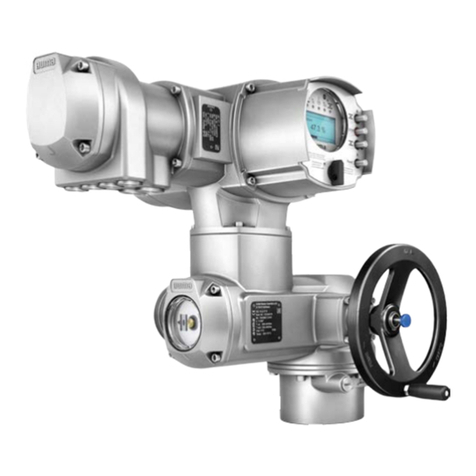
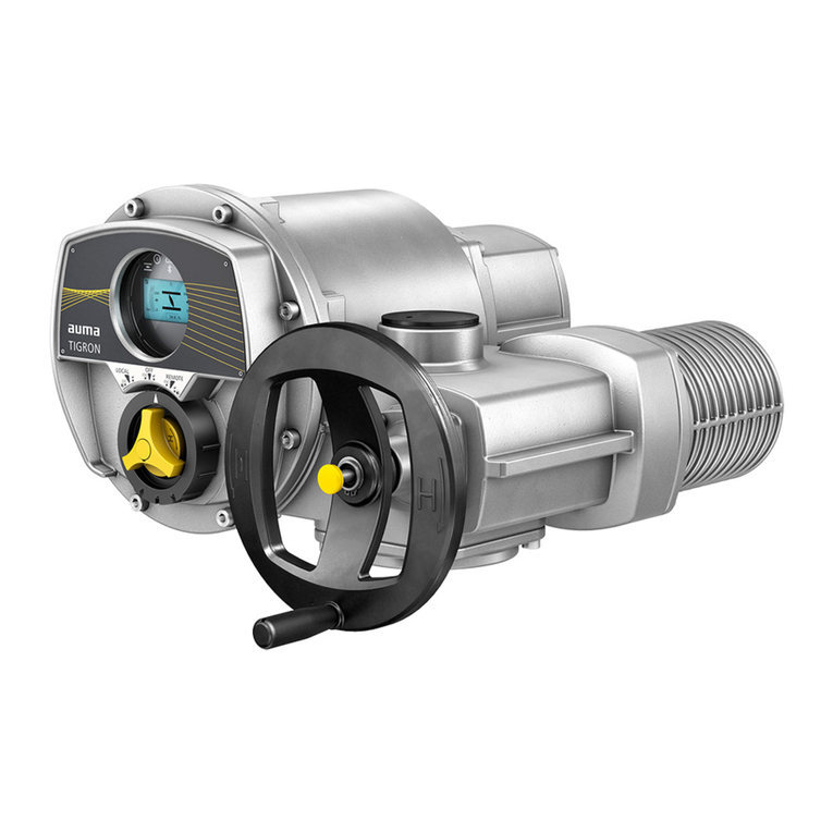
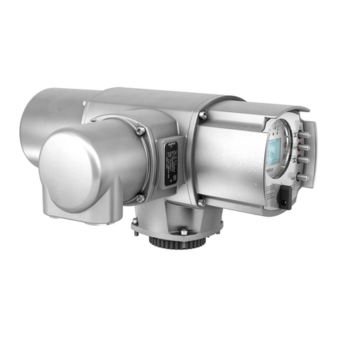
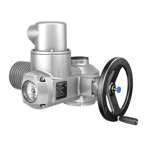
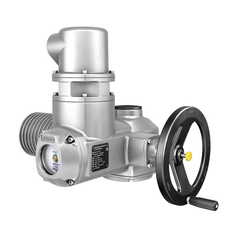
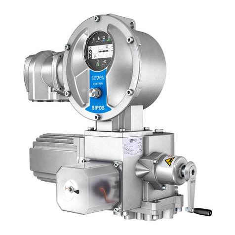
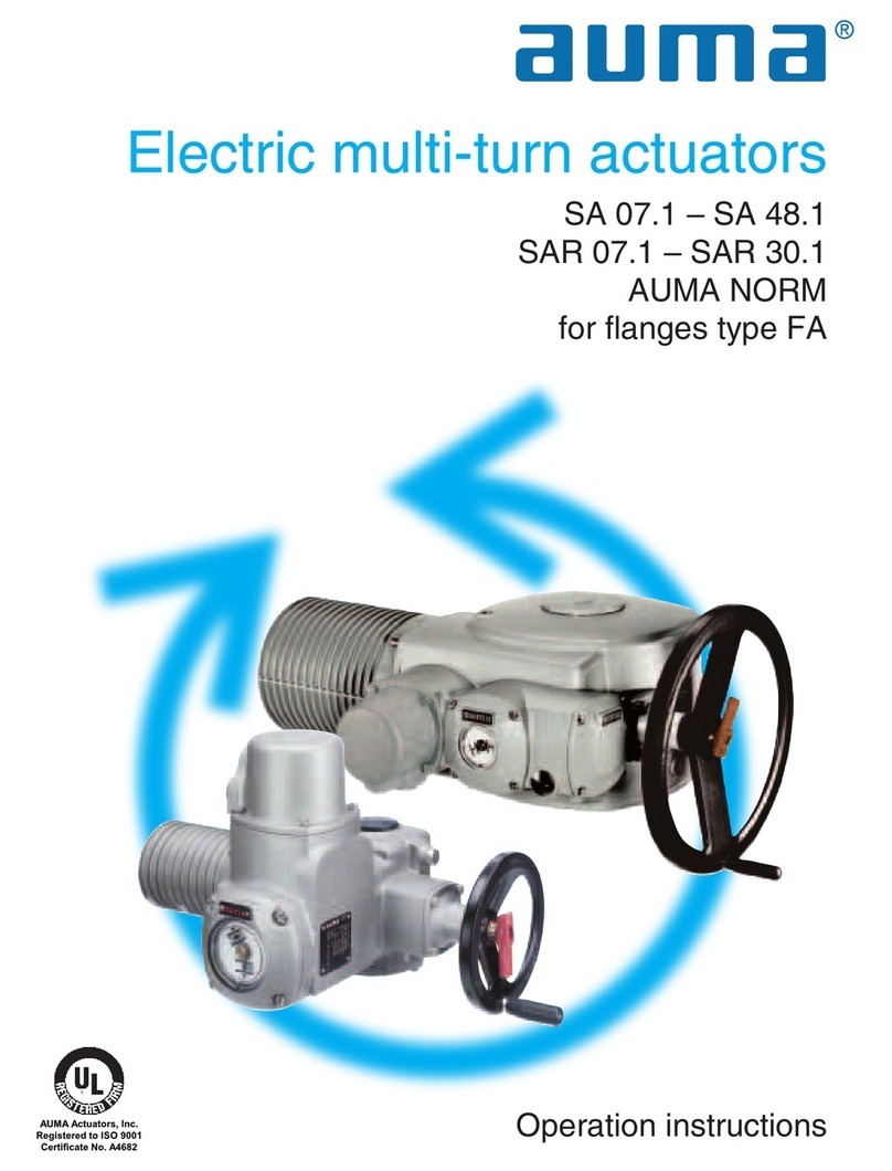
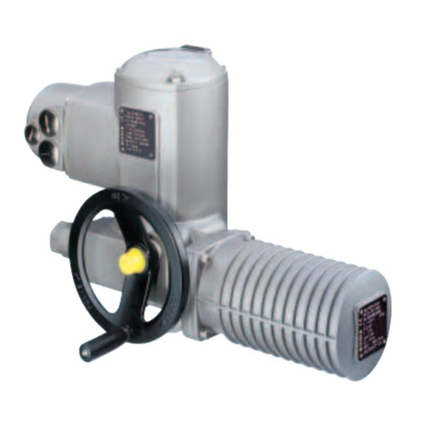
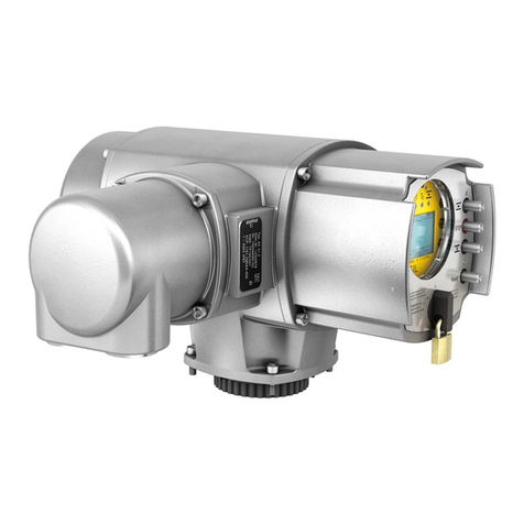
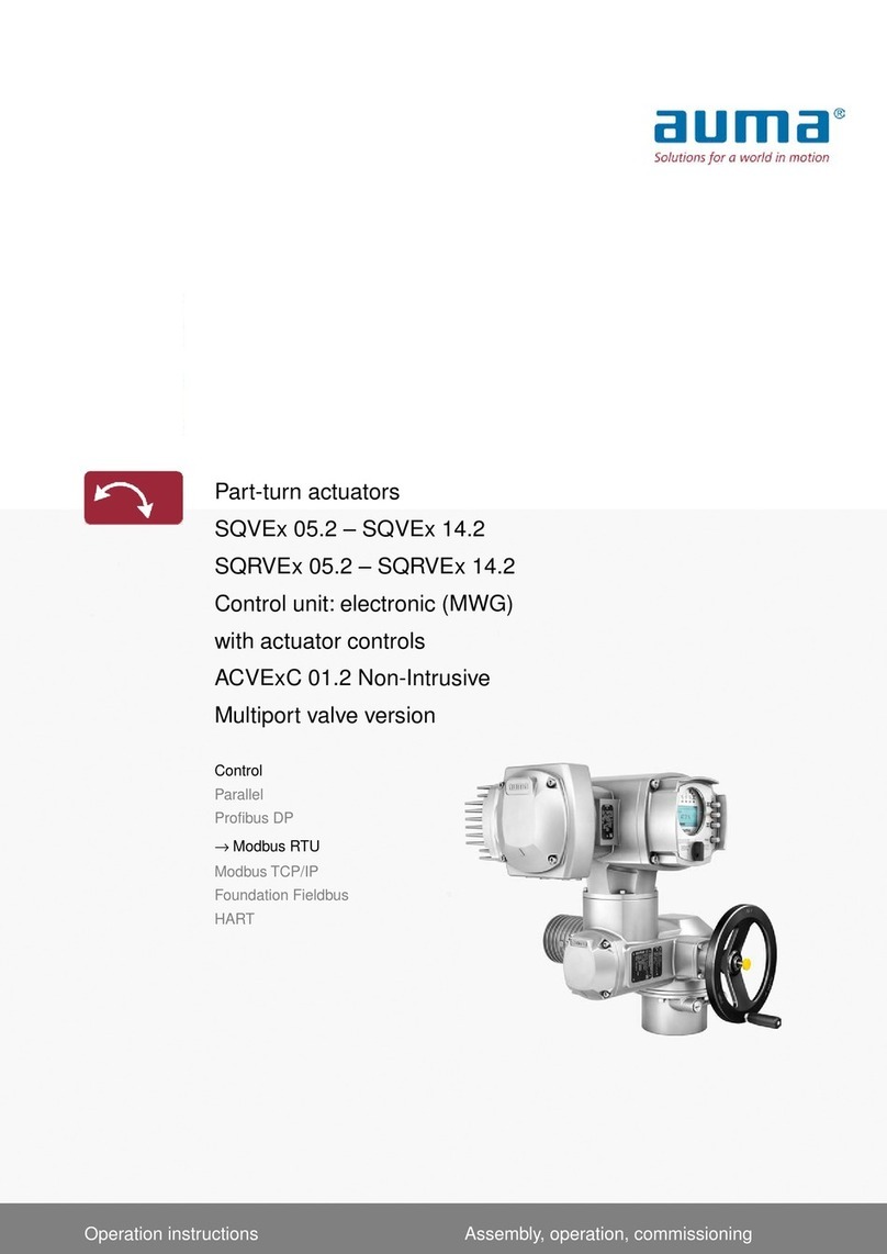
AUMA SA Series User manual

Multi-turn actuators
SA 07.2 –SA 16.2/SAR 07.2 –SAR 16.2
SAEx 07.2 –SAEx 16.2/SAREx 07.2 –SAREx 16.2
with actuator controls
AC 01.2-SIL/ACExC 01.2-SIL
SIL version
Functional SafetyManual

NOTICE for use!
This document is only valid in combination with the current operation instructions enclosed with the device.
Purpose of the document:
The present documents informs about the actions required for using the device in safety-related systems in
accordance with IEC 61508 or IEC 61511.
Reference documents:
●Operation instructions (Assembly, operation, commissioning) for actuator
●Manual (Operation and setting) AUMATIC AC 01.2
●Manual (Device integration Fieldbus) AUMATIC AC 01.2/ACExC 01.2
●Technical data on multi-turn actuator and on actuator controls
Reference documents can be downloaded from the Internet (www.auma.com) or ordered directly from AUMA
(refer to <Addresses>).
Table of contents Page
41. Terminology............................................................................................................................ 41.1. Abbreviations and concepts
62. Application and validity......................................................................................................... 62.1. Range of application 62.2. Standards 62.3. Valid device types
73. Architecture, configuration and applications...................................................................... 73.1. Architecture (actuator sizing) 83.2. Configuration (setting)/version 93.3. Applications (environmental conditions)
114. Safety instrumented systems and safety functions........................................................... 114.1. Safety instrumented system including an actuator 114.2. Safety functions 124.3. Safe inputs and outputs 124.4. Redundant system architecture 134.5. Examples of applications 144.6. System representation
155. Installation, commissioning and operation......................................................................... 155.1. Installation 165.2. Commissioning 175.3. Operation 175.4. Lifetime 175.5. Decommissioning
186. Indications on display............................................................................................................ 186.1. Status indications on SIL functions 196.2. SIL configuration warning 196.3. Backlight
207. Signals..................................................................................................................................... 207.1. Signals via SIL module 207.2. SIL fault signal via standard controls display (for troubleshooting support)
2
Multi-turn actuators
Table of contents SA 07.2 –SA 16.2/SAR 07.2 –SAR 16.2

217.3. Status signals via output contacts (digital outputs) of standard controls 217.4. Signal via fieldbus of standard controls
238. Tests and maintenance.......................................................................................................... 238.1. Safety equipment: check 238.2. Internal actuator monitoring with control via standard controls 238.3. Partial Valve Stroke Test (PVST): execute 248.4. Proof test (verification of safe actuator function) 258.4.1. Safe ESD safety operation (Safe OPENING/CLOSING) 268.4.2. SIL fault signal "Actuator monitoring": check 268.4.3. Safe ESD reaction for "Motor protection (thermal fault)" signals:check 278.4.4. Safe ESD reaction to "Limit seating with overload protection" (limit and/or torque eval-
uation): check 298.4.5. Safe ESD reaction to "Forced limit seating in end position" (limit evaluation) –for actu-
ators with electromechanical control unit: check 298.4.6. Safe ESD reaction for "Forced limit seating in end position" (limit evaluation) –for actu-
ators with electronic control unit and limit switches: check 308.4.7. Safe ESD reaction to "Forced torque seating in end position" (torque after limit evalu-
ation): check 318.4.8. Safe ESD reaction for "No seating" (no evaluation of limit and torque): check 328.4.9. Safe STOP function: check 338.4.10. Combination of Safe ESD and Safe STOP function: check 348.5. Maintenance
359. Safety-related figures............................................................................................................. 359.1. Determination of the figures 369.2. Specific figures for AC 01.2 controls in SIL version with actuators of SA.2 series
3910. SIL Certificate.........................................................................................................................
4011. Checklists............................................................................................................................... 4011.1. Commissioning checklist 4011.2. Proof test checklists 4011.2.1. Safe ESD safety operation (Safe OPENING/CLOSING) 4011.2.2. SIL fault signal "Actuator monitoring" 4111.2.3. Safe ESD reaction to "Motor protection (thermal fault)" signals 4211.2.4. Safe ESD reaction to "Limit seating with overload protection" (limit and/or torque eval-
uation) 4211.2.5. Safe ESD reaction to "Forced limit seating in end position" (limit evaluation) –for actu-
ators with electromechanical control unit 4311.2.6. Safe ESD reaction to "Forced limit seating in end position" (limit evaluation) –for actu-
ators with electronic control unit and limit switches 4411.2.7. Safe ESD reaction to "Forced torque seating in end position" (torque after limit evalu-
ation) 4411.2.8. Safe ESD reaction to "No seating" 4511.2.9. Safe STOP function 4611.2.10. Combination of Safe ESD and Safe STOP
49Index........................................................................................................................................
50Addresses...............................................................................................................................
3
Multi-turn actuators
SA 07.2 –SA 16.2/SAR 07.2 –SAR 16.2 Table of contents

1. Terminology
Information sources ●IEC 61508-4, Functional safety of electrical/electronic/programmable electronic
safety-related systems –Part 4: Definitions and abbreviations
●IEC 61511-1, Functional safety - Safety instrumented systems for the process
industry sector –Part 1:Framework, definitions, system, hardware and software
requirements
1.1. Abbreviations and concepts
To evaluate safety functions, the lambda values or the PFD value (Probability of
Dangerous Failure on Demand) and the SFF value (Safe Failure Fraction) are the
main requirements.Further figures are required to assess the individual components.
These figures are explained in the table below.
Table 1: Abbreviations of safety figures
DescriptionFull expressionAbbrevi-
ation Number of safe failuresLambda Safe
λSNumber of dangerous failuresLambda Dangerous
λDNumber of undetected dangerous fail-
ures
Lambda Dangerous Undetected
λDU
Number of detected hazardous failuresLambda Dangerous Detected
λDD Diagnostic Coverage - ratio between
the failure rate of dangerous failures
detected by diagnostic tests and total
rate of dangerous failures of the com-
ponent or subsystem.The diagnostic
coverage does not include any failures
detected during proof tests.
Diagnostic CoverageDC
Mean time between the occurence
between two subsequent failures
Mean Time Between FailuresMTBF
Fraction of safe failures as well as of
detected hazardous failures
Safe Failure FractionSFF
Average probability of dangerous fail-
ures on demand of a safety function.
Average Probability of dangerous Fail-
ure on Demand
PFDavg
Ability of a functional unit to execute a
required function while faults or devi-
ations are present.HFT = n means that
the function can still be safely executed
for up to n faults occurring at the same
time.
Hardware Failure ToleranceHFT
Interval for proof testProof test intervalTproof
SIL Safety Integrity Level
The international standard IEC 61508 defines 4 levels (SIL 1 through SIL 4).
Safety function Function to be implemented by a safety-related system for risk reduction with the
objective to achieve or maintain a safe state for the plant/equipment with respect to
a specific hazardous event.
Safety instrumented
function (SIF) Function with specified safety integrity level (SIL) to achieve functional safety.
Safety instrumented
system (SIS) Safety instrumented system for executing a single or several safety instrumented
functions.An SIS consists of sensor(s), logic system and actuator(s).
Safety-related system A safety-related system includes all factors (hardware, software, human factors)
necessary to implement one or several safety functions. Consequently failures of
safety function would result in a significant increase in safety risks for people and/or
the environment.
A safety-related system can comprise stand-alone systems dedicated to perform a
particular safety function or can be integrated into a plant.
4
Multi-turn actuators
Terminology SA 07.2 –SA 16.2/SAR 07.2 –SAR 16.2

Proof test Periodic test performed to detect dangerous hidden failures in a safety-related system
so that, if necessary, a repair can restore the system to an "as new" condition or as
close as practical to this condition.
MTTR (MeanTimeTo
Restoration) Mean time to restoration once a failure has occurred. Indicates the expected mean
time to achieve restoration of the system.It is therefore an important parameter for
system availability.The time for detecting the failure, planning tasks as well as
operating resources is also included.It should be reduced to a minimum.
MRT (Mean RepairTime) Mean repair time indicates the mean time required to repair a system.The MRT is
crucial when defining the reliability and availability of a system.The MRT should
preferably be small.
Device type (type A and
type B) Actuator controls can be regarded as type A devices if all of the following conditions
are met for all components required to achieve the safety instrumented function:
●The failure modes for all constituent components involved are well defined
●The behaviour under fault conditions can be completely determined.
●There is sufficient dependable failure data from the field to show that the claimed
rates of failure are met (confidence level min. 70 %).
Actuator controls shall be regarded as type B devices if one or several of the following
conditions are met:
●The failure of at least one constituent component is not well defined.
●The fault behaviour is not completely known.
●There is insufficient dependable failure data to support claims for rates of failure
for detected and undetected dangerous failures.
PTC (ProofTest Cover-
age) Proof test coverage describes the fraction of failures which can be detected by means
of a proof test.
5
Multi-turn actuators
SA 07.2 –SA 16.2/SAR 07.2 –SAR 16.2 Terminology

2. Application and validity
2.1. Range of application
AUMA actuators and actuator controls in SIL version are intended for operation of
industrial valves and are suitable for use in safety instrumented systems in accordance
with IEC 61508 or IEC 61511.
2.2. Standards
Both actuators and actuator controls meet the following requirements:
●IEC 61508 ED.2: Functional safety of electrical/electronic/programmable elec-
tronic safety-related systems
2.3. Valid device types
The data on functional safety contained in this manual applies to the device types
indicated hereafter.
Table 2: Overview on suitable device types
Power supplyType MotorControlsActuator 3-phase AC currentAC 01.2 in SIL versionSA 07.2 –SA 16.2 3-phase AC currentAC 01.2 in SIL versionSAR 07.2 –SAR 16.2 3-phase AC currentACExC 01.2 in SIL versionSAEx 07.2 –SAEx 16.2 3-phase AC currentACExC 01.2 in SIL versionSAREx07.2 –SAREx16.2
6
Multi-turn actuators
Application and validity SA 07.2 –SA 16.2/SAR 07.2 –SAR 16.2

3. Architecture, configuration and applications
3.1. Architecture (actuator sizing)
For actuator architecture (actuator sizing) the maximum torques, running torques
and operating times are taken into consideration.
Incorrect actuator architecture can lead to device damage within the safety-
related system!
Possible consequencescanbevalve damage,motor overheating,contactor jamming,
defective thyristors, heating up or damage to cables.
→The actuator technical data must imperatively be observed when selecting the
actuator.
→Sufficient reserves have to be provided to ensure that actuators are capable of
reliably opening or closing the valve even in the event of an accident or under-
voltage.
Architecture when using the Safe STOP function
Information For the Safe STOP function, the motor is switched off, overrun may possibly occur!
Valve damage due to overrun!
→For the Safe Stop function (SS), the overrun of the arrangement (actuator,
gearbox, valve) and the reaction time have to be observed.
→If the application requires self-locking of the actuator, please consult AUMA.
Architecture when using the Safe ESD function
Actuators with electromechanical control unit:
End position signalling (limit switching) and torque signalling via the electromechanical
control unit are safe signals which may be integrated into a safety-related system.
For "SIL seating" = "no seating" (without end position protection), we recommend:
●To prevent valve damage during safety operation, we recommend, depending
on the stiffness, sizing the valve to 3 –5 times the maximum actuator torque.
●To avoid thermal damage due to excessive currents, we recommend monitoring
(assessing) the motor protection.
Actuator with electronic control unit MWG:
Information End position signalling (limit switching) and torque signalling via the electronic control
unit MWG are not considered as safe signals.
●In case safe signals are required, they have to be implemented differently, e.g.
using switches on the valve.
●To prevent valve damage during safety operation, we recommend, depending
on the stiffness, sizing the valve to 3 –5 times the maximum actuator torque.
●To avoid thermal damage due to excessive currents, we recommend monitoring
(assessing) the motor protection.
Actuators with electronic control unit MWG including limit switches:
Information In this version, safe signalling can exclusively be ensured via limit switches.
For "SIL seating" = "no seating" (without end position protection), we recommend:
●To prevent valve damage during safety operation, we recommend, depending
on the stiffness, sizing the valve to 3 –5 times the maximum actuator torque.
●To avoid thermal damage due to excessive currents, we recommend monitoring
(assessing) the motor protection.
7
Multi-turn actuators
SA 07.2 –SA 16.2/SAR 07.2 –SAR 16.2 Architecture, configuration and applications

Information For "SIL seating" = "forced limit seating in end position", the seating is performed
via limit switches in the end position.Since each switch has a hysteresis, the actuator
leaves the end position prior to limit switch release.Consequently, there is a marginal
range of actuator positions to the safety position, for which the limit switch is still
operated when leaving the safety position while the Safe ESD function is NOT
available. In this case, safety function triggering leads to actuator standstill. If the
range in question is approached from the opposite direction, this limitation does not
apply.In general this range is relatively low.However, for unfavourable configurations
(low number of turns per stroke), this range can amount to more than 10 % of the
total stroke.
Should within the framework of unfavourable conditions the effect described above
represent an unacceptable limitation for the safety function, we recommend applying
the configuration "forced torque seating in end position" or "no seating" for safety
operation.
Power supply
Information The plant operator is responsible for power supply.
3.2. Configuration (setting)/version
Configuration (setting) of safety-related functions is adjusted in the factory during
controls assembly and validated during final inspection. Subsequent modification of
the configuration by the plant operator is not permissible.
General functions are set as described in the Operation instructions or the Manual
(Operation and setting) AUMATIC AC 01.2.
Configuration of safety-related functions is listed in the order-related technical data
sheet.
Configuration options for safety function
Table 3: Configuration options for safety function
Short descriptionConfiguration
SIL function Safe CLOSINGSafe ESD CLOSE/CLOSE Safe OPENINGSafe ESD OPEN/OPEN Safe STOP in direction CLOSE and direction OPENSafe STOP CLOSE/OPEN Safe CLOSING and Safe STOP in direction CLOSE
and direction OPEN
Safe ESD CLOSE/CLOSE + Safe
STOP CLOSE/OPEN Safe OPENING and Safe STOP in direction CLOSE
and direction OPEN
Safe ESD OPEN/OPEN + Safe
STOP CLOSE/OPEN
Seating configuration options
Information Seating of standard actuator controls should be configured as set forth in the tables
below.
8
Multi-turn actuators
Architecture, configuration and applications SA 07.2 –SA 16.2/SAR 07.2 –SAR 16.2

Table 4: For actuators with electromechanical control unit:
Configuration
Type of seating
Standard controls
Short descriptionConfiguration
SIL seating type
Freely selectableNo seating by limit or torque switches dur-
ing safety operation
1: No seating
Torque seatingSafety operation is stopped if both limit and
torque switches trip simultaneously
2:Forced torque seat-
ing in end position Limit seatingSafety operation is stopped by limit switch
tripping
3: Forced limit seating
in end position Limit seatingSafety operation is stopped by tripping the
limit switches and/or the torque switches
(overload protection).
4: Limit seating with
overload protection
Table 5: For actuators with electronic control unit MWG
Configuration
Type of seating
Standard controls
Short descriptionConfiguration
SIL seating type
Freely selectableNo seating by limit or torque switches dur-
ing safety operation
1: No seating
Table 6: For actuators with electronic control unit MWG including limit switches
Configuration
Type of seating
Standard controls
Short descriptionConfiguration
SIL seating type
Limit seatingSafety operation is stopped by limit switch
tripping
3: Forced limit seating
in end position
Configuration options for motor protection assessment
Table 7: Configuration options for motor protection assessment
Short descriptionConfiguration
SIL motor protection Tripping of the motor protection (thermal fault) stops or prevents safety
operation
Active
Motor protection has no impact on the safety operationInactive
Information "SIL motor protection" = "inactive" configuration is only set if explicitly required.The
version does not meet the Ex approval requirements.
3.3. Applications (environmental conditions)
When specifying and using the actuators within safety instrumented systems, make
sure that the permissible service conditions and the EMC requirements by the
peripheral devices are met.Service conditions are indicated in the technical data
sheets:
●Enclosure protection
●Corrosion protection
●Ambient temperature
●Vibration resistance
If the actual ambient temperatures exceed an average of +40 °C, the lambda values
have to be incremented by a safety factor. For an average temperature of +60 °C,
this factor is specified to 2.5.
For environmental test, actuator and actuator controls were subjected to the following
standards:
●Dry heat: EN 60068-2-2
●Damp heat: EN 60068-2-30
●Cold: EN 60068-2-1
9
Multi-turn actuators
SA 07.2 –SA 16.2/SAR 07.2 –SAR 16.2 Architecture, configuration and applications

●Vibration test: IEC 60068-2-6
●Induced seismic vibration (earthquake): IEC 68-3-31)
●Enclosure protection test IP68: EN 60529
●Salt spray test: EN ISO 12944-6
●Immunity requirements: EN 61326-3-1
●Emission: EN 61000-6-4
1) Thyristor version only
10
Multi-turn actuators
Architecture, configuration and applications SA 07.2 –SA 16.2/SAR 07.2 –SAR 16.2

4. Safety instrumented systems and safety functions
4.1. Safety instrumented system including an actuator
Typically, a safety instrumented system including an actuator is composed of the
components as shown in the figure.
Figure 1:Typical safety instrumented system
[1] Sensor
[2] Controls (standard and safety PLC)
[3] Actuator with actuator controls
[4] Valve
[5] Process control system
Thesafetyintegrity level is alwaysassigned to an overall safety instrumented system
and not to an individual component.
For an individual component (e.g. an actuator), safety instrumented figures are
determined.These figures are used to assign the devices to a potential safety integrity
level (SIL).The final classification of the safety instrumented system can only be
made after assessing and calculating all subsystems.
4.2. Safety functions
In calculating the safety actuator figures, the following safety functions are taken into
account:
●Safe ESD function (Emergency Shut Down): Safe OPENING/CLOSING
-Redundant Safe ESDa and Safe ESDb signals (standard:low active) make
the actuator travel to the configured direction (OPEN/CLOSE).
11
Multi-turn actuators
SA 07.2 –SA 16.2/SAR 07.2 –SAR 16.2 Safety instrumented systems and safety functions

●Safe STOP function: Safe STOP
-Anoperationcommand ofstandard controls(in directionsOPEN or CLOSE)
will only be executed if an additional enable signal for the operation com-
mand is applied.
-If this is not the case, operation in directions OPEN or CLOSE is stopped
or even suspended (motor is switched off).
●Safe ESD function combined with Safe STOP function
-Safe ESD function has a higher priority i.e.if both functions are activated,
the actuator is operated into the configured direction (OPEN/CLOSE).
The different configuration options of the safety functions are described in the
<Configuration (setting)/version> chapter.
4.3. Safe inputs and outputs
Safe inputs for Safe OPENING/CLOSING (Safe ESD function):
●Safe ESDa
●Safe ESDb
Safe inputs for safe stop (Safe STOP function):
●Safe STOP OPEN
●Safe STOP CLOSE
Safe outputs (indication that it might not be possible to perform the safety function:
●SIL failure
●SIL ready
For detailed information on safe inputs and outputs, refer to <Configuration
(setting)/version> chapter and <Installation> chapter.
4.4. Redundant system architecture
Besides the already described typical safety instrumented system including an
actuator, safety can be increased by integrating a second, redundant valve and
actuator with actuator controls in SIL version into the safety instrumented system.
The decision on the correct version depends on the entire system.With the redundant
system architecture shown below, actuator and actuator controls achieve SIL 3 in
accordance with IEC 61508.
Figure 2: Redundant system with Safe ESD for Safe CLOSING
12
Multi-turn actuators
Safety instrumented systems and safety functions SA 07.2 –SA 16.2/SAR 07.2 –SAR 16.2

Figure 3: Redundant system with Safe ESD for Safe OPENING
4.5. Examples of applications
Safe OPENING of a pressure vessel using the Safe ESD function
The standard PLC controls the entire system. A system fault occurs if excessive
pressure is generated within the system.In this case, the safety PLC immediately
opens the valve for safe pressure relief.
Figure 4: Application example:Pressure vessel
13
Multi-turn actuators
SA 07.2 –SA 16.2/SAR 07.2 –SAR 16.2 Safety instrumented systems and safety functions

Safe stop of locks to prevent destruction using the Safe STOP function.
Operationsafety(preventing hazardsto persons and systems) is of utmost importance
for locks.Once the lock closes, no boats must be between the gates.Otherwise, the
Safe STOP function (e.g. via EMERGENCY Stop button) is executed.
Figure 5: Application example: Lock
4.6. System representation
The representation below shows the simplified design of an AC 01.2/ACExC 01.2
in SIL version.
Figure 6: Simplified system representation
14
Multi-turn actuators
Safety instrumented systems and safety functions SA 07.2 –SA 16.2/SAR 07.2 –SAR 16.2

5. Installation, commissioning and operation
Information Installation and commissioning have to be documented by means of an assembly
report and an inspection certificate.Installation must be carried out exclusively by
suitably qualified personnel.
The plant operator is responsible for ensuring power supply protection against
overvoltage and undervoltage during execution of a safety function.
5.1. Installation
General installation tasks (assembly, electrical connection) have to be performed
according to the operation instructions pertaining to the device and the enclosed
order-specific wiring diagram.
When operating and storing the devices in ambient temperatures below –25 °C,
ensure power supply of integral heating system.
Safety functions are connected via the SIL module integrated in the AC 01.2/ACExC
01.2 actuator controls.
SIL fault must be connected to a SIL 2 compatible input of a safety PLC and
subsequently analysed.
Figure 7: Connections for safety functions via SIL module
[1] Connections for parallel control
[2] Connections for fieldbus control
Input switching behaviour of Safe ESDa/ESDb and Safe STOP
OPEN/CLOSE:
●Input level = high level (standard: +24 V DC)
= No safety operation for Safe ESD function or
= No safe stop for Safe STOP function
●Input signal = low level (0 V DC or input open)
= Failure operation for Safe ESD function or
= Safe stop for Safe STOP function
Permissible input voltage range:
●High level: 15 –30 V DC
●Low level: max. 5 V DC
Signal behaviour of SIL ready and SIL failure outputs:
●SIL ready (signal inactive), i.e.:
NO (NO contact) output = closed
NC (NC contact) output = open
15
Multi-turn actuators
SA 07.2 –SA 16.2/SAR 07.2 –SAR 16.2 Installation, commissioning and operation

●SIL failure (signal active), i.e.:
NO (NO contact) output = open
NC (NC contact) output = closed
Customer connections for controlSignalDesignation
Wiring diagram [2] Fieldbus[1] Parallel XK 3XK 31Digital input for Safe ESD functionSafe ESDa XK 5XK 32Redundant input for Safe ESD functionSafe ESDb XK 7XK 33Reference potential for Safe ESDa and Safe ESDb0 V XK 8XK 35Digital input for Safe STOP function in direction CLOSESafe STOP CLOSE XK 9XK 37Reference potential for Safe STOP CLOSE0 V XK 10XK 36Digital input for Safe STOP function in direction OPENSafe STOP OPEN XK 11XK 38Reference potential for Safe STOP OPEN0 V XK 15XK 40NO contact of SIL fault signalSIL ready XK 14XK 39NC contact of SIL fault signalSIL failure XK 16XK 42Reference potential for SIL fault signalCom.
SIL fault displayed via SIL failure output
DescriptionFault causes
SIL Motor protection trippedThermal fault Torque fault in directions OPEN and/or CLOSETorque fault Current position feedback is outside permissible range.Fault position feed-
back One phase of power supply is missing.
Controls are not supplied with mains voltage
Phase failure
The phase conductors L1, L2 and L3 are connected in the wrong sequence.Phase sequence
fault The safety-related part of controls is without power supply.Power supply failure Temperature within controls housing too high
Failure of heating system for ambient temperatures below –25 °C
Temperature fault
Actuator of valve lockedFailure of actuator
monitoring Both signals Safe ESDa and Safe ESDb are not simultaneously on the same level.Fault in redundant
wiring Safe ESD Internal error of the SIL moduleInternal error
For further information on SIL faults and in particular to assist in troubleshooting,
refer to chapter <Indications>.
Information The basic function "automatic correction of direction of rotation" is not available for
this version.When connecting the power supply ensure that phases L1, L2 and L3
are correctly connected. For checking the direction of rotation, refer to operation in-
structions pertaining to the actuator.
The "external supply of electronics" option of the actuator controls refers to standard
actuator controls.In case of mains failure, the SIL module would no longer be
operable despite external supply of the electronics.
5.2. Commissioning
The operation instructions pertaining to the device must be observed for general
commissioning.
Information For the Safe ESD function, operation into the safe position can be performed irre-
spective of the selector switch position (LOCAL - OFF - REMOTE) or the operating
status.Even in positions LOCAL and OFF or at system start, can the actuator start
by triggering the safety function.
16
Multi-turn actuators
Installation, commissioning and operation SA 07.2 –SA 16.2/SAR 07.2 –SAR 16.2

Risk of immediate actuator start when switching on if the motor/handwheel
locking device was removed while the motor was in disengaged position!
Risk of personal injuries or damage to the valve
→Ensure that high level is present at the Safe ESDa/ESDb inputs when
switching on (standard: +24 V DC).
If the actuator is operated over a longer period (for several hours) while the
motor is disengaged, this entails considerable wear of the actuator.Worst
case would be accidental start-up or even destruction of the actuator.
On delivery, the motor is disengaged to prevent accidental start-up of the actuator
as well as consequential personal injuries or damage to the valve.
If the actuator is connected to 3-phase AC current without high level is present at
the Safe ESDa/ESDb inputs (default: +24 V DC), the motor will start without any
movement at the output drive.
→Operational actions have to be provided ensuring that the described state only
persists for a short time, i.e.a few minutes at the maximum.
→Remove the motor locking device prior to commissioning. It must only be used
for a short time during proof test.
After commissioning, the safe actuator function must be verified. Refer to <Proof
test> chapter.
5.3. Operation
Regular maintenance and device checks in determined Tproof intervals are the basis
for safe operation.The figures indicated in the <Safety figures> chapter are valid for
Tproof = 1 year.
For operation, both the pertaining operation instructions and the Manual (Operation
and setting) AUMATIC AC 01.2 have to be observed.
In case of possible failures or defects of the safety system, safe function must be
guaranteed by introducing alternative actions.Furthermore, a detected fault including
fault description has to be sent to AUMA Riester GmbH & Co. KG. Autonomous
repair work by the plant operator is not permitted.
5.4. Lifetime
Lifetime of actuators is described in the technical data sheets or the operation
instructions.
Safety-related figures are valid for the cycles or modulating steps defined in the
technical data specifications for typical periods of up to 10 years (the criterion
achieved first is valid). After this period, the probability of failure increases.
5.5. Decommissioning
When decommissioning an actuator with safety functions, the following must be
observed:
●Impact of decommissioning on relevant devices, equipment or other work must
be evaluated.
●Safety and warninginstructionscontained in the actuator operation instructions
must be met.
●Decommissioning must be carried out exclusively by suitably qualified personnel.
●Decommissioning must be recorded in compliance with regular requirements.
17
Multi-turn actuators
SA 07.2 –SA 16.2/SAR 07.2 –SAR 16.2 Installation, commissioning and operation

6. Indications on display
This section contains indications of standard controls only available in SIL version .
General indications as well as settings and operation are described in the pertaining
operation instructions and in the Manual (Operation and setting) AUMATIC AC 01.2.
Information Indications on the display are not part of a safety function!They must not be integrated
in a safety-related system!
The indications support the user on site at the device, making the safety function
status easily discernible.
6.1. Status indications on SIL functions
Actuator controls may indicate status information on safety-related functions on the
display.
SIL status (S0013)
Indication S0013 signals the safety function and the SIL fault indication status.
If the SIL symbol is shown in the header of the display, one of the following three
indications is active:Safe ESD, Safe STOP or SIL fault.
Figure 8: Safety function and SIL fault indication status
StatusStatus indications on
display SafeESD function (SafeOPENING/CLOSING) is active:Actuator
is operated in the configured direction (CLOSE/OPEN) (inputs
Safe ESDa/Safe ESDb = 0 V or open)
Safe ESD
Safe STOP function is active, actuator stops (Safe STOP
OPEN or Safe STOP CLOSE = 0 V or open inputs)
Safe STOP
SIL fault signal active, i.e. possible problems when executing a
safety function (Safe ESD or Safe STOP).
SIL fault
Warnings (S0005)
Indication S0005 shows the numbers of warnings having occurred.
In case a SIL fault occurs, the SIL fault message is listed in indication S0005. Refer
to Details > Status for further details.
Figure 9:Warning: SIL fault
Not ready REMOTE (S0006)
Indication S0006 shows the number of occurring messages which are part of the
Not ready REMOTE group.
If a safety function is active (Safe ESD or Safe STOP), the indication is listed in the
SIL function active Not ready REMOTE group. Refer to Details > Status for further
details.
18
Multi-turn actuators
Indications on display SA 07.2 –SA 16.2/SAR 07.2 –SAR 16.2

Figure 10: Signal: Safety function active
Information As soon as a safety function is active (SIL function active indication), the actuator is
controlled via the safety PLC and the SIL module. For “normal control”(standard
PLC), controls are therefore “Not ready REMOTE”.
6.2. SIL configuration warning
In combination with the safety functions, the following configurations or settings of
standard controls may have an impact on the standard functions:
●Self-retaining Local M0076 = OPEN/CLOSE
●Self-retaining Remote M0100 = OPEN/CLOSE
If one of these configurations is selected in the standard controls, the device generates
the SIL config. warning.
6.3. Backlight
In standard operation, display backlight of actuator controls is white. In the event of
a fault, the display backlight is red.The red backlight does NOT refer to the safety
function status but to the faults referred to as "faults" in the Manual (Operation and
setting) AUMATIC AC 01.2.
19
Multi-turn actuators
SA 07.2 –SA 16.2/SAR 07.2 –SAR 16.2 Indications on display

7. Signals
7.1. Signals via SIL module
The integrated SIL module signals a SIL fault via an output contact (SIL ready
or SIL failure outputs). Only these signals may be used in a safety-related
system.
For the signal behaviour of the SIL ready/SIL failure outputs, refer to
<Installation> chapter.
Once a SIL fault occurs, the system has to be checked immediately and the
installation has to be put in a safe state, if required.
7.2. SIL fault signal via standard controls display (for troubleshooting support)
If the SIL module output contact (SIL ready or SIL failure outputs) signals
a SIL fault, the exact fault can be determined via the indication in the standard controls
display.For details on all fault indications and warning indications on the standard
controls display, refer to Manual (Operation and setting) AUMATIC AC 01.2.
The SIL module output contact serves as collective signal for the faults listed in the
table below.
Table 8: Individual signals of SIL fault collective signal
Impact on safety function
→Remedy
Description/
cause of fault
Indication on display
Standard controls For version “SIL motor protection”= active:
●The Safe ESD safe function cannot be executed.
●If the fault is triggered during safety operation, operation is
stopped.
Remedy
→Cool down, wait.
Motor protection tripped.
Thermal fault
For “SIL seating”= “"Limit seating with overload protection”
configuration:
●The Safe ESD safe function cannot be executed.
●If the fault is triggered during safety operation, operation is
stopped.
Remedy
→Execute operation command in opposite direction.
→Verify torque switching setting.
→Check whether foreign object prevents the valve from closing.
→Possibly problems with the valve.
Torque fault in directions
CLOSE or OPEN
Torque fault in directions
CLOSE and OPEN (simultan-
eously).
Torque fault CLOSE
Torque fault OPEN
For configurations “SIL seating”= “Limit seating with overload
protection”, “SIL seating”=“Forced limit seating in end posi-
tion”, or “SIL seating”=“Forced torque seating in end position”:
●The Safe ESD safe function cannot be executed.
●If the fault is triggered during safety operation, operation is
stopped.
Remedy
→Verify reduction gearing settings within the actuator.
→In case of possible defect at the actuator: Contact AUMA service
Current position feedback sig-
nal range is outside the per-
missible range.
Both limit switches (OPEN and
CLOSED) are operated simul-
taneously.
Possibly defect at actuator
mechanics.
Wrn range act.pos.
●The Safe ESD safe function cannot be executed.
●The Safe STOP safe function is indirectly executed as the motor
is no longer supplied with power.
Remedy
→Test/connect phases.
One phase of power supply is
missing.
Controls are not supplied with
mains voltage
Phase fault
In case of wrong phase sequence, the actuator is operated into the
wrong direction during safety operation.
Remedy
→Correct the sequence of the phase conductors L1, L2 and L3 by
exchanging two phases.
The phase conductors L1, L2
and L3 are connected in the
wrong sequence.
Incorrect phase seq
20
Multi-turn actuators
Signals SA 07.2 –SA 16.2/SAR 07.2 –SAR 16.2
Other manuals for SA Series
3
This manual suits for next models
11
Table of contents
Other AUMA Controllers manuals
AUMA
AUMA AUMATIC AC 01.2 User manual

AUMA
AUMA PROFOX PF-M25X User manual
AUMA
AUMA SGR 05.1 User manual

AUMA
AUMA AMB 01.1 User manual

AUMA
AUMA SQVEx 05.2 User manual

AUMA
AUMA SAM Ex 07.1 User manual

AUMA
AUMA SGM Series User manual

AUMA
AUMA SG 03.3 User manual

AUMA
AUMA Aumatic ACExC 01.1 User manual

AUMA
AUMA SA 07.2 User manual