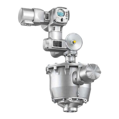
AUMA GS 50.3 User manual

Gearboxes
GS 50.3 –GS 250.3
GK 10.2 –GK 40.2
SFC version
Functional safetyManual

NOTICE for use!
This document is only valid with the latest operation instructions attached to the device, the attached declaration
of incorporation as well as the pertaining technical data sheets.They are understood as reference documents.
Purpose of the document:
The present document informs about the actions required for using the device in safety-related systems in
accordance with IEC 61508 or IEC 61511.
Reference documents:
●exida report no.AUMA 15/10-108 R014 and AUMA 12/02-079 R007
●Operation instructions (Assembly, commissioning) and Technical data for gearbox
Reference documents are available on the Internet at: http://www.auma.com.
Table of contents Page
31. Terminology............................................................................................................................ 31.1. Abbreviations and concepts
52. Application and validity......................................................................................................... 52.1. Range of application 52.2. Standards 52.3. Valid device types
63. Architecture, configuration and applications...................................................................... 63.1. Architecture (gearbox sizing) 63.2. Configuration (setting) 63.3. Protection against uncontrolled operation (self-locking/brake) 63.4. Operation mode (low/high demand mode) 63.5. Further notes and indications on architecture 63.6. Applications (environmental conditions)
84. Safety instrumented systems and safety functions........................................................... 84.1. Safety functions
95. Installation, commissioning and operation......................................................................... 95.1. Installation 95.2. Commissioning 95.3. Operation 95.4. Lifetime 95.5. Decommissioning
106. Tests and maintenance.......................................................................................................... 106.1. Safety equipment: check 106.2. Proof test (verification of safe gearbox function) 106.3. Maintenance
117. Safety-related figures............................................................................................................. 117.1. Determination of the safety-related figures
128. SIL Declaration of Conformity (example).............................................................................
16Index........................................................................................................................................
17Addresses...............................................................................................................................
2
Gearboxes
Table of contents

1. Terminology
Information sources ●IEC 61508-4, Functional safety of electrical/electronic/programmable electronic
safety-related systems –Part 4: Definitions and abbreviations
●IEC 61511-1, Functional safety - Safety instrumented systems for the process
industry sector –Part 1:Framework, definitions, system, hardware and software
requirements
1.1. Abbreviations and concepts
To evaluate safety functions, the lambda values or the PFD value (Probability of
Dangerous Failure on Demand) and the SFF value (Safe Failure Fraction) are the
main requirements.Further figures are required to assess the individual components.
These figures are explained in the table below.
Table 1:Abbreviations of safety figures
DescriptionFull expressionAbbrevi-
ation Number of safe failuresLambda SafeλSNumber of dangerous failuresLambda DangerousλDNumber of undetected dangerous fail-
ures
Lambda Dangerous UndetectedλDU
Number of detected dangerous failuresLambda Dangerous DetectedλDD Diagnostic Coverage - ratio between
the failure rate of dangerous failures
detected by diagnostic tests and total
rate of dangerous failures of the com-
ponent or subsystem.The diagnostic
coverage does not include any failures
detected during proof tests.
Diagnostic CoverageDC
Mean time between the occurence of
two subsequent failures
Mean Time Between FailuresMTBF
Fraction of safe failures as well as of
detectable dangerous failures
Safe Failure FractionSFF
Average probability of dangerous fail-
ures on demand of a safety function.
Average Probability of dangerous Fail-
ure on Demand
PFDavg
Ability of a functional unit to execute a
required function while faults or devi-
ations are present.HFT = n means that
the function can still be safely executed
for up to n faults occurring at the same
time.
Hardware Fault ToleranceHFT
Interval for proof testProof test intervalTproof
SIL Safety Integrity Level
The international standard IEC 61508 defines 4 levels (SIL 1 through SIL 4).
Safety function Function to be implemented by a safety-related system for risk reduction with the
objective to achieve or maintain a safe state for the plant/equipment with respect to
a specific dangerous event.
Safety instrumented
function (SIF) Function with specified safety integrity level (SIL) to achieve functional safety.
Safety instrumented
system (SIS) Safety instrumented system for executing a single or several safety instrumented
functions.An SIS consists of sensor(s), logic system and actuator(s).
Safety-related system A safety-related system includes all factors (hardware, software, human factors)
necessary to implement one or several safety functions. Consequently failures of
safety function would result in a significant increase in safety risks for people and/or
the environment.
A safety-related system can comprise stand-alone systems dedicated to perform a
particular safety function or can be integrated into a plant.
3
Gearboxes Terminology

Proof test Periodic test performed to detect dangerous hidden failures in a safety-related system
so that, if necessary, a repair can restore the system to an "as new" condition or as
close as practical to this condition.
MTTR (MeanTimeTo
Restoration) Mean time to restoration once a failure has occurred. Indicates the expected mean
time to achieve restoration of the system.It is therefore an important parameter for
system availability.The time for detecting the failure, planning tasks as well as
operating resources is also included.It should be reduced to a minimum.
4
Gearboxes
Terminology

2. Application and validity
2.1. Range of application
AUMA gearboxes with the safety functions mentioned in this manual are intended
for operation of industrial valves and are suitable for use in safety instrumented
systems in accordance with IEC 61508 or IEC 61511.
2.2. Standards
IEC 61508-2:2010 The safety figures of the devices described meet the requirements of IEC 61508 in
the respective SIL level with regard to failure rates and architecture requirements.
However, this does not imply that all further requirements of IEC 61508 are met.
2.3. Valid device types
The data on functional safety contained in this manual applies to the device types
indicated.
Table 2: Overview on suitable device types
Safety functionDuty classVersionGearboxes Safe operation in direction
OPEN/CLOSE
No indicationsIn SFC versionGK 10.2 –GK 40.2
Safe operation in direction
OPEN/CLOSE
Duty class 1In SFC versionGS 50.3 –GS 250.3
Gearboxes may not be modified without prior written consent by AUMA.Unauthorised
modifications may have a negative impact on both safety figures and SIL capability
of the products.
Information In applications with requirements on functional safety, only AUMA gearboxes in SFC
or SIL version may be used. SFC stands for “Safety Figure Calculated”.This desig-
nation identifies AUMA products for which safety figures were calculated on the basis
of FMEDA from field data and generic data (for detailed information refer to <Determ-
ination of the figures>).
AUMA gearboxes in SFC version can among others be identified from the letters
"SFC" following the type designation on the name plate.
Figure 1: Example of name plate with “SFC”marking
5
Gearboxes Application and validity
This manual suits for next models
3
Table of contents
Other AUMA Industrial Equipment manuals
