manuals.online logo
Brands
  1. Home
  2. •
  3. Brands
  4. •
  5. WURM
  6. •
  7. Control Unit
  8. •
  9. WURM EEV module User manual

WURM EEV module User manual

EEV module
Product information
EEV-Modul_V1.30_PI_2018-01_EN Subject to technical changes Page 1 of 4
Front view
Control module for electronic expansion valves
Features
Control by data interface of a CRD-XP/CRDP-XP
1 digital switching channel and 1 analogue voltage output
1 input for temperature sensor and 1 input for pressure transmitter
No parameters need to be set
Circuit diagram
LED Status Meaning
TxD Fast flashing EEV module transmitting data to the
cold location controller.
RXD Fast flashing EEV module receiving data from cold
location controller.
EEV Illuminated EEV being controlled via normally
open contact on terminal 35.
EEV
RxD LEDs
TxD
EEV module
Product information
Page 2 of 4 Subject to technical changes EEV-Modul_V1.30_PI_2018-01_EN
Writing conventions
Symbol Meaning
CAUTION! Avoid the described hazard: otherwise minor or medium physical
injury or damage to property will result.
WARNING! Avoid the described hazard: otherwise there is danger from electric
voltage that could lead to death or serious physical injury.
For your safety
For safe operation and to avoid personal injury and equipment damage through operating
error, always read these instructions, become familiar with the device, and follow all safety
instructions on the product and in this document, as well as the safety guidelines of Wurm
GmbH & Co. KG Elektronische Systeme. Keep these instructions ready to hand for quick
reference and pass them on with the device if the product is sold.
Wurm GmbH & Co. KG Elektronische Systeme accepts no liability in case of improper use or
use for other than the intended purpose.
Target group These instructions are intended for "service technicians".
Intended use The EEV module is a control module for electronic expansion
valves.
WARNING!
Danger to life from electric shock and/or fire!
Switch off the power to the entire plant when installing, wiring or removing!
Otherwise a mains voltage and/or external voltage may still be present even if
the control voltage is switched off!
The wiring of the device should be carried out only by a qualified electrician!
Use only the correct tools for all work!
Check all wiring after connection!
Take note of the maximum loads on all connections!
Never expose the device to moisture, for example due to condensation or
cleaning agents!
Take the device out of operation if it is faulty or damaged and is therefore
compromising safe operation!
Do not open the device!
Do not repair the device yourself! If required, send it in for repair with an exact
description of the fault!
CAUTION!
Electromagnetic interference can cause faults!
Use only shielded data lines and place them far away from power lines!
Software revisions and validity of documentation
Software version
V1.30 2018-01 Documentation status
Any software versions not listed are special solutions for individual projects and are not described in detail in this document.
This document automatically ceases to be valid if a new technical description is issued.
Manufacturer: Wurm GmbH & Co. KG Elektronische Systeme, Morsbachtalstraße 30, D-42857 Remscheid
For further information, see our website at www.wurm.de
EEV module
Product information
EEV-Modul_V1.30_PI_2018-01_EN Subject to technical changes Page 3 of 4
Function
The EEV module communicates with an appropriately equipped FRIGOENTRY cold location
controller via the EEV-Data interface. The measured values of the pressure transmitter and
temperature sensor are transmitted to the cold location controller. The adjustment signals
that the EEV module receives from the cold location controller are output on the analogue
and digital outputs of the EEV module in order to control electronic expansion valves.
Start-up
Connection diagram
Monitoring and emergency programmes
If communication to a cold location controller fails, then the outputs are controlled with an
emergency setpoint. This is set on the cold location controller.
Installation
Installing the EEV module
This device is designed for top-hat rail installation. The housings are standard size and are
also suitable for installation in installation boxes. They can be positioned side by side without
gaps.
Notes!
Check all wiring before start-up!
The parameter that defines the refrigerant
being used is set in the cold location
controller.
EEV module
Product information
Page 4 of 4 Subject to technical changes EEV-Modul_V1.30_PI_2018-01_EN
Installing the temperature sensor
To ensure reliable operation of the electronic expansion valve, it is important to take special
care when installing the suction gas temperature sensor.
Never fasten the suction gas temperature sensor with cable
straps. Fasten it with a copper strap in the appropriate clock
position. The clock position depends on the tube diameter
(see fig.: “Installing the suction gas sensor”).
Abb.: Installing the suction gas sensor
Sensor extension: We recommend the use of shielded cables for sensor extension.
Cable length Cross section
up to 100m 0.75mm²
up to 400m 1.5mm²
Technical data Power supply 230V~, +10% / -15%, approx. 2.6VA
Temperature sensor 1 x TRK-EEV/7ST
Analogue input 4…20mA
Semiconductor relay output 1 x 230V~, 4…60VA, note the minimum output!
Residual voltage measureable! Integrated semiconductor
protection (no isolator).
Analogue output 0…10V=, non-isolated, max. load 1mA
Central unit Single-chip microcomputer
Monitoring system Monitoring of communication, microcontroller self-monitoring
Communication Serial interface
Dimensions (WxHxD) 53 x 90 x 58mm (DIN 43880)
Fastening Top-hat rail TH 35-15 or TH 35-7.5 (DIN EN 60715)
Ambient temperature Operation: 0...+55°C, storage: -25...+70°C
Weight About 300g
CE conformity 2014/30/EU (EMC Directive)
2014/35/EU (Low Voltage Directive)
EAC conformity TR CU 004/2011
TR CU 020/2011
RoHS II
Valid from Version 1.30
Notes!
In general, a suction gas temperature
sensor is installed in exactly the same
manner as the sensor cartridges of
thermostatic valves. For low temperature
cold locations, watertight insulation of the
sensor is absolutely essential. There must
be no formation of pads of ice on or around
the sensor.
Ensure that the sensor is fastened close to
the evaporator, but not in a channel where
refrigerant could accumulate.

Other WURM Control Unit manuals

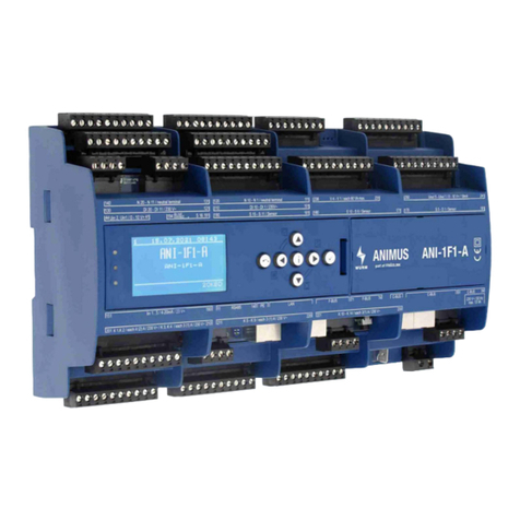
WURM HCO2-G4 User manual

WURM

WURM HCO2-G4 User manual

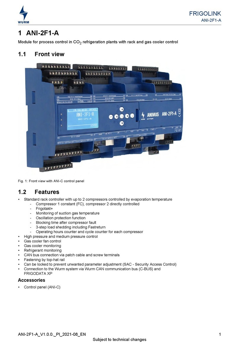
WURM FRIGOLINK ANI-2F1-A User manual

WURM

WURM FRIGOLINK ANI-2F1-A User manual

WURM FRIGOLINK ANI-1F1 User manual

WURM

WURM FRIGOLINK ANI-1F1 User manual
WURM HMS-G3 User manual

WURM

WURM HMS-G3 User manual

WURM FRIGOLINK ANI-1F1 User manual

WURM

WURM FRIGOLINK ANI-1F1 User manual

WURM FGT004 User manual

WURM

WURM FGT004 User manual

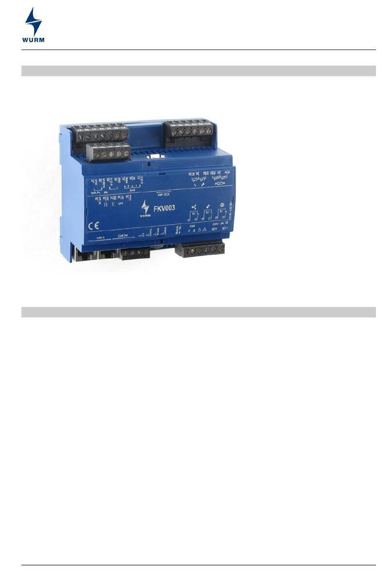
WURM FKV003 User manual

WURM

WURM FKV003 User manual

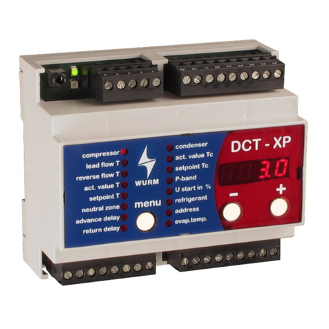
WURM DCT-XP User manual

WURM

WURM DCT-XP User manual

WURM FRIGOLINK ANI-1F3 User manual

WURM

WURM FRIGOLINK ANI-1F3 User manual

WURM FVB240-PAT User manual

WURM

WURM FVB240-PAT User manual

WURM DSC-XP User manual

WURM

WURM DSC-XP User manual

WURM FKL003-A User manual

WURM

WURM FKL003-A User manual

WURM DOC-XP User manual

WURM

WURM DOC-XP User manual

WURM FKV003 User manual

WURM

WURM FKV003 User manual

WURM FVB140-PAT User manual

WURM

WURM FVB140-PAT User manual

WURM FKV003-A User manual

WURM

WURM FKV003-A User manual

WURM Frigolink FVB110B User manual

WURM

WURM Frigolink FVB110B User manual
WURM FVB110-PAT User manual

WURM

WURM FVB110-PAT User manual

WURM FRIGOLINK ANI-2F1-A User manual

WURM

WURM FRIGOLINK ANI-2F1-A User manual

WURM HVL-G3 User manual

WURM

WURM HVL-G3 User manual

WURM FKL003-A User manual

WURM

WURM FKL003-A User manual
WURM FKL003 User manual

WURM

WURM FKL003 User manual

WURM FRIGOLINK ANI-1F1-A User manual

WURM

WURM FRIGOLINK ANI-1F1-A User manual

Popular Control Unit manuals by other brands

Novus DigiRail Connect Series instruction manual

Novus

Novus DigiRail Connect Series instruction manual

Texas Instruments TAS2563 user guide

Texas Instruments

Texas Instruments TAS2563 user guide

LG PVDATN000 Installation & owner's manual

LG

LG PVDATN000 Installation & owner's manual

chip45 Crumbuino-Mega Info sheet

chip45

chip45 Crumbuino-Mega Info sheet

CommScope SYSTIMAX 360 InstaPATCH 3603M UHD instructions

CommScope

CommScope SYSTIMAX 360 InstaPATCH 3603M UHD instructions

DSC PC5400 installation manual

DSC

DSC PC5400 installation manual

Leviton 110A00-1 Installation instructions and user guide

Leviton

Leviton 110A00-1 Installation instructions and user guide

Trio MC464 Quick connection guide

Trio

Trio MC464 Quick connection guide

DSC IT-100 installation instructions

DSC

DSC IT-100 installation instructions

Toto TSU99A.X manual

Toto

Toto TSU99A.X manual

Watts AMES 930GD-01 Installation, operation and maintenance manual

Watts

Watts AMES 930GD-01 Installation, operation and maintenance manual

Stobag SRCR 100 A Instructions and warnings for the fitter

Stobag

Stobag SRCR 100 A Instructions and warnings for the fitter

Siemens SINUMERIK 840D Description of Functions

Siemens

Siemens SINUMERIK 840D Description of Functions

Sony BKM-16R Operation manual

Sony

Sony BKM-16R Operation manual

Episode EVC-100R installation guide

Episode

Episode EVC-100R installation guide

Kidde AEGIS 84-732001-001 Installation, operation and maintenance manual

Kidde

Kidde AEGIS 84-732001-001 Installation, operation and maintenance manual

Henco HENCOLOGIC CU-6ZONEB-H quick start guide

Henco

Henco HENCOLOGIC CU-6ZONEB-H quick start guide

Siemens CP 5611 Installation Instructions / Product Information

Siemens

Siemens CP 5611 Installation Instructions / Product Information

manuals.online logo
manuals.online logoBrands
  • About & Mission
  • Contact us
  • Privacy Policy
  • Terms and Conditions

Copyright 2025 Manuals.Online. All Rights Reserved.