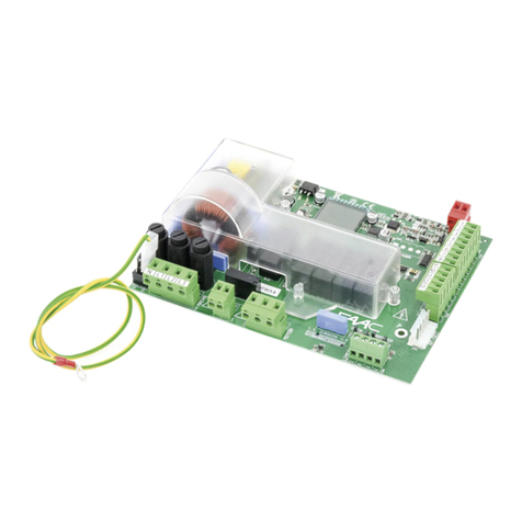
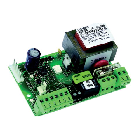
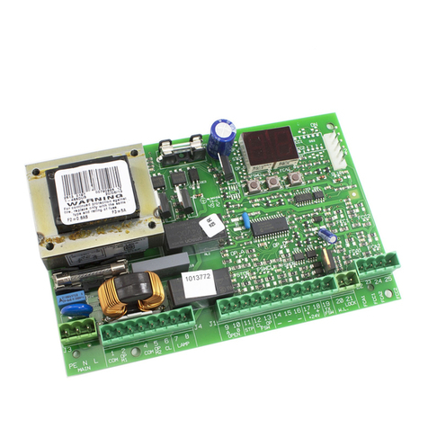
FAAC XR2 433 C User manual

XR2 433 C
XR2 868 C

1
0
70
32,5
90
105
98
DL1
SW1 SW2
DL2
CH1 CH2
5
DL3
6
7
8
10
11
12
+
91 2
N.O. N.O.
DS1
14
2
3
ITALIANO
2 CARATTERISTICHE TECNICHE
XR2 433 C - XR2 868 C
XR2 433 C XR2 868 C
ALIMENTAZIONE (V) 12/24 ac-dc 12/24 ac-dc
FREQUENZA DI RICEZIONE (MHz) 433.92 ±0.1 868.35±0.2
CORRENTE ASSORBITA (mA) 100 mA 100 mA
DECODIFICA (SISTEMA OMNIDEC) DS-LC-SLH DS-SLH
CODICI MEMORIZZABILI 250 250
NUMERO CANALI 22
NUMERO USCITE A RELE’ (N.O.) N 1 impulsiva (CH 1)
N 1 impulsiva / fissa (selezionabile)(CH2)
N 1 impulsiva (CH 1)
N 1 impulsiva / fissa (selezionabile)(CH2)
PORTATA CONTATTO RELE’ 0.5 A / 120 VA 0.5 A / 120 VA
GRADO DI PROTEZIONE IP 44 IP 44
TEMPERATURA DI FUNZIONAMENTO (°C)
-20 / +55 -20 / +55
/Prefratturazione per pressacavi
0Coperchio
1Predispozione per fissaggio su guida DIN
2Attacchi per fissaggio tramite viti
3Morsetti per uscita comando (N.O.)
4Contatto a relè normalmente aperto (N.O.)
5Led si segnalazione ( ON = USCITA ATTIVA )
DL1=LED CH 1 DL2=LED CH2
6Pulsanti di programmazione radio
SW1=PULSANTE CH1 SW2=PULSANTE CH2
7DS1:Dipswitch di selezione
8Morsetto per alimentazione
9Morsetto per antenna
:DL3: Led di presenza rete ( ON = PRESENZA RETE )
1 DESCRIZIONE
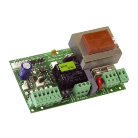
L’apparecchiatura elettronica XR2 C è una ricevente esterna bi-canale, provvista di un sistema di decodifica integrato
(DS, SLH, LC), chiamato OMNIDEC. Quando un canale viene attivato tramite radiocomando (DS, SLH, LC)), il rispettivo
contatto a relè N.O. si chiude con le modalità descritte al capitolo 5.
Le configurazioni selezionabili sono le seguenti:
CH1= uscita a relè N.O. ad impulso
CH2= uscita a relè N.O. ad impulso / fissa ( selezionabile tramite DS1 )
Fig.1
DS1 ON OFF
DIP
SWITCH 1
USCITA
CANALE 2
FISSA
USCITA
CANALE 2
IMPULSIVA
DIP
SWITCH 2 NON USATO NON USATO

2
ITALIANO
3 MEMORIZZAZIONE DEI RADIOCOMANDI
Sull’apparecchiatura XR2 C può coesistere al
massimo una tipologia di codifica radio
(DS, SLH, LC) .
E’ possibile memorizzare max. 250 codici divisi
tra i canali 1 e 2
3 MEMORIZZAZIONE DEI RADIOCOMANDI
3.1
MEMORIZZAZIONE DEI RADIOCOMANDI
DS
3.2
MEMORIZZAZIONE DEI RADIOCOMANDI
SLH
1) Sul radiocomando SLH master premere e tenere pre-
muti i pulsanti P1 e P2 contemporaneamente.
2) Il led del radiocomando inizierà a lampeggiare (per
circa 10 sec.)
3) Lasciare entrambi i pulsanti.
4) Premere, per 1 secondo, il pulsante sulla ricevente (Fig.1
rif. 6) corrispondente al canale a cui si vuole associare il
radiocomando.
5) Il led corrispondente sulla ricevente (Fig.1 rif. 5), inizia
a lampeggiare lentamente per 5 sec.
6) Entro questi 5 sec. mentre il led del radiocomando
sta ancora lampeggiando, premere e tenere premuto il
pulsante desiderato sul radiocomando (il led del radio-
comando si accenderà a luce fissa).
7) Il led sulla scheda (Fig.1 rif. 5) si accenderà a luce fissa
per 1 secondo per poi spegnersi, indicando l’avvenuta
memorizzazione.
8) Rilasciare il pulsante del radiocomando.
9) Premere per 2 volte, il pulsante del radiocomando
memorizzato, in breve successione.
La scheda invierà,all’uscita associata al canale,
un comando.
10) Per aggiungere altri radiocomandi, è necessario tra-
sferire il codice del pulsante del radiocomando memo-
rizzato al pulsante corrispondente dei radiocomandi da
aggiungere, seguendo la seguente procedura:
a) Sul radiocomando memorizzato premere e tenere
premuti i pulsanti P1 e P2 contemporaneamente.
b) Il led del radiocomando inizierà a lampeggiare.
c) Lasciare entrambi i pulsanti.
d) Premere il pulsante memorizzato e tenerlo premuto (il
led del radiocomando si accenderà a luce fissa).
e) Avvicinare i radiocomandi, premere e tenere premuto
il pulsante corrispondende del radiocomando da aggiunge
re, rilasciandolo solo dopo il doppio lampeggio del led del
radiocomando che indica l’avvenuto apprendimento
- Premere per 2 volte il pulsante del nuovo radiocomando
memorizzato, in breve successione.
La scheda invierà,all’uscita associata al canale,
un comando.
3.3
MEMORIZZAZIONE DEI RADIOCOMANDI
LC
1) Premere sulla ricevente, per 1 secondo, il pulsante (Fig.1
rif. 6) corrispondente al canale a cui si vuole associare
il radiocomando.
2) Sulla ricevente, il led corrispondente (Fig.1 rif. 5) inizia
a lampeggiare lentamente per 5 sec.
3) Entro questi 5 sec. premere il pulsante desiderato sul
telecomando LC.
4) Il led sulla ricevente (Fig.1 rif. 5) si accenderà a luce fissa
per 1 secondo, indicando l’avvenuta memorizzazione,
per poi riprendere a lampeggiare per altri 5 sec. durante
i quali si può memorizzare un altro radiocomando.
5) Terminati i 5 sec. il led si spegne indicando la fine della
procedura.
6) Per memorizzare altri radiocomandi ripetere la prece-
dente procedura.
Se si vuole procedere in modo remoto (senza aprire il con-
tenitore la ricevente) seguire la seguente procedura:
a) Prendere un radiocomando già memorizzato.
b) Premere e tenere premuti i pulsanti P1 e P2 contempo-
raneamente fino all’accensione a luce lampeggiante
del led (Fig.1 rif. 5) sulla scheda ricevente.
c) Il led lampeggerà lentamente per 5 sec.
d) Entro 5 sec. premere il pulsante precedentemente
memorizzato del radiocomando per attivare la fase di
apprendimento sul canale selezionato.
e) Il led sulla scheda corrispondente al canale in appren-
dimento lampeggia per 5 sec. entro i quali si deve
trasmettere il codice di un altro radiocomando.
f) Il led (Fig.1 rif. 5) si accende a luce fissa per 2 sec., in-
dicando l’avvenuta memorizzazione, per poi riprendere
a lampeggiare per 5 sec. durante i quali si può ripetere
il punto “e” , ed i successivi, per altri telecomandi, ed
infine spegnersi.
La codifica radio LC è disponibile solo per alcuni
mercati e solo per la ricevente XR2 433C.
1) Per cancellare TUTTI i codici dei radiocomandi associati
ai canali 1e 2, è sufficiente tenere premuto il pulsante
SW1 o SW2 (Fig.1 rif. 6), per 10 sec.
2) Il led corrispondente (Fig.1 rif. 5) al pulsante premuto
lampeggerà per i primi 5 sec. per poi lampeggiare più
velocemente per i successivi 5 sec.
3) Il led si accenderà a luce fissa per 2 sec. per poi spe-
gnersi.
4) Rilasciare il pulsante premuto nel momento in cui il led
corrispondente si accende a luce fissa.
4
CANCELLAZIONE DI TUTTI I RADIOCOMAN
DI
Questa operazione NON è reversibile.
1) Sul radiocomando DS scegliere la combinazione
ON - OFF desiderata dei 12 dip switches.
2) Premere, per 1 secondo, il pulsante sulla ricevente
(Fig.1rif. 6), corrispondente al canale a cui si vuole
associare il radiocomando.
3) Il led corrispondente sulla ricevente (Fig.1 rif. 5), inizia
a lampeggiare lentamente per 5 sec.
4) Entro questi 5 sec. premere il pulsante desiderato sul
radiocomando.
5) Il led (Fig.1 rif. 5) sulla ricevente si accenderà fisso per
1 secondo per poi spegnersi, indicando l’avvenuta
memorizzazione.
La scheda invierà,all’uscita associata al
canale, un comando.
6) Per aggiungere altri radiocomandi è necessario im-
postare la stessa combinazione ON - OFF utilizzata al
punto 1).

3
ITALIANO
5 LOGICA DI FUNZIONAMENTO
CANALE
1
CANALE
2
DIP SWITCH 1 OFF
CANALE
2
DIP SWITCH 1 ON
USCITA 1 IMPULSO / /
USCITA 2
/ IMPULSO
CONTATTO CHIUSO FINO AL
PROSSIMO IMPULSO DA
RADIOCOMANDO
E’ possibile far comandare i canali della ricevente da radiocomandi diversi. (Es: Il radiocomando 1
comanda il canale 1, il radiocomando 2 comanda il canale 2 )
IMPULSO DA RADIOCOMANDO

1
0
70
32,5
90
105
98
DL1
SW1 SW2
DL2
CH1 CH2
5
DL3
6
7
8
10
11
12
+
91 2
N.O. N.O.
DS1
14
2
3
ENGLISH
2 TECHNICAL SPECIFICATIONS
XR2 433 C - XR2 868 C
XR2 433 C XR2 868 C
POWER SUPPLY (V) 12/24 ac-dc 12/24 ac-dc
RECEPTION FREQUENCY (MHz) 433.92 ±0.1 868.35±0.2
ABSORBED CURRENT (A) 100 mA 100 mA
DECODING (OMNIDEC SYSTEM) DS-LC-SLH DS-SLH
SAVEABLE CODES 250 250
NUMBER OF CHANNELS 22
NUMBER OF RELAY OUTPUTS (N.O.) N 1 pulsed (CH1)
N 1 pulsed/fixed (selectable) (CH2)
N 1 pulsed (CH1)
N 1 pulsed/fixed (selectable) (CH2)
RELAY CONTACTS CAPACITY 0.5 A / 120 VA 0.5 A / 120 VA
PROTECTION CLASS IP 44 IP 44
OPERATING AMBIENT TEMPERATURE (°C)
-20 / +55 -20 / +55
/Preperforated facility for cable grippers
0Cover
1Facility for securing on DIN guide
2Fittings for screw securing
3Terminals for command output (N.O.)
4Normally open (N.O.) relay contact
5Signalling LEDs (ON= OUTPUT ACTIVE)
DL1=LED CH 1 DL2=LED CH2
6Radio programming push-buttons
SW1=PUSH-BUTTON CH1
SW2=PUSH-BUTTON CH2
7DS1:Selection dip-switch
8Power supply terminal
9Terminal for antenna
:DL3: Mains ON LED ( ON = MAINS PRESENT )
1 DESCRIPTION
The XR2 C control board is a two-channel external receiver, which has an integrated decoding system (DS, SLH, LC),
named OMNIDEC. When a channel is activated by radio control (DS, SLH, LC), the relevant N.O. relay contact closes
by the methods described in chapter 5.
The selectable configurations are:
CH1 = pulsed N.O. relay output
CH2 = pulsed/fixed N.O relay output (selectable by DS1)
Fig.1
DS1 ON OFF
DIP
SWITCH 1
OUTPUT
CHANNEL 2
FIXED
OUTPUT
CHANNEL 2
PULSED
DIP
SWITCH 2 NOT USED NOT USED

2
ENGLISH
3 MEMORIZZAZIONE DEI RADIOCOMANDI
At the most, only one type of radio coding can
coexist on the XR2 C board.
(DS, SLH, LC) .
A maximum of 250 codes, divided between
channels 1 and 2 can be stored in the memory.
3 MEMORY STORAGE OF RADIO CONTROLS
3.1 MEMORY STORAGE OF DS RADIO CONTROLS
3.2 MEMORY STORAGE OF SLH RADIO CONTROLS
1) On the SLH master radio control, simultaneously press
and hold down push-buttons P1 and P2.
2) The radio control LED begins to flash (for about 10
secs.).
3) Release both push-buttons.
4) Press, for 1 second, the push-button on the receiver
(Fig.1 ref.6) relating to the channel you wish to associate
with the radio control.
5) The relevant LED on the receiver (Fig. 1 ref. 5) begins
to flash slowly for 5 secs.
6) Within these 5 secs., while the radio control LED is still
flashing, press and hold down the required push-button
on the radio control (the radio control LED lights up on
steady beam).
7) The LED on the board (Fig.1 ref.5) lights up on steady
beam for 1 second and then goes OFF, indicating that
storage was executed.
8) Release the radio control push-button.
9) Quickly press twice in succession the memory stored
radio control push-button.
The board will send a command to the output
associated with the channel.
10) To add other radio controls, transfer the code of the
memory-stored push-button of the radio control to the
relevant push-button of the radio controls to be added,
observing the following procedure:
a) On the memory stored radio control, simultaneously press and
hold down push-buttons P1 and P2.
b) The radio control LED begins to flash.
c) Release both push-buttons.
d) Press the memory stored push-button and hold it down (the
radio control LED lights up on steady beam).
e) Bring the radio controls near, press and hold down the push-
button of the radio control to be added, releasing it only after
the double flash of the radio control LED, which indicates learning
was executed.
- Quickly press twice the push-button of the new memory
stored radio control.
The board will send a command to the output
associated with the channel.
3.3 MEMORY STORAGE OF LC RADIO CONTROLS
1) Press, for 1 second, the push-button on the receiver (Fig.1
ref.6) relating to the channel you wish to associate with
the radio control.
2) The relevant LED on the receiver (Fig. 1 ref. 5) begins
to flash slowly for 5 secs.
3) Within these 5 secs., press the appropriate push-button
on the LC remote control.
4) The LED on the receiver (Fig.1 ref.5) lights up on steady
beam for 1 second, indicating memory storage
executed, and then resumes flashing for another
5 secs., during which another radio control can be
memory stored.
5) When the 5 secs. have elapsed, the LED goes OFF
indicating the end of the procedure.
6) To memory store other radio controls, repeat the
previous procedure.
If you wish to proceed in remote mode, (without opening
the receiver container), follow the procedure below:
a) Take an already memory stored radio control.
b) Press and simultaneously hold down push-buttons P1
and P2 until the flashing light of the LED (Fig.1 ref.5) on
the receiver board lights up.
c) The LED will flash slowly for 5 secs.
d) Within 5 secs. press the push-button of the radio control
that had been memory stored to enable learning on
the selected channel.
e) The LED on the board relating to the channel being
learned flashes for 5 secs., within which time the code
of another radio control must be transmitted.
f) The LED (Fig.1 ref.5) lights up on steady beam for 2
seconds, indicating memory storage executed, and
then resumes flashing for 5 secs., during which point “e”
can be repeated, and also the subsequent points, for
other remote controls and finally goes OFF.
The LC radio coding is available only for certain
markets and only for receiver XR2 433C.
1) To delete ALL the radio control codes associated with
channels 1 and 2, hold down push-button SW1 or SW2
(Fig.1 ref.6) for 10 seconds.
2) The LED (Fig.1 ref. 5) relating to the pressed push-button
flashes for the first 5 secs., and then flashes more quickly
for the next 5 secs.
3) The LED lights up on steady beam for 2 secs and then
goes OFF.
4) Release the pressed push-button when both the relevant
LED lights up on a steady beam.
4
DELETION OF ALL RADIO CONTROLS
This operation is NOT reversible.
1) On the DS radio control, select the required ON-OFF
combination for the 12 dip-switches.
2) Press for 1 second the push-button on the receiver (Fig.1
ref.6) relating to the channel you wish to associate with
the radio control.
3) The relevant LED on the receiver (Fig. 1 ref. 5) begins
to flash slowly for 5 secs.
4) Within these 5 secs., press the appropriate push-button
on the radio control.
5) The relevant LED (Fig.1 ref. 5) lights up on steady beam
for 1 second and then goes OFF, indicating that storage
was executed.
The board will send a command to the output
associated with the channel.
6) To add other radio controls, set the same ON - OFF
combination used in point 1).

3
ENGLISH
5 FUNCTION LOGIC
CHANNEL
1
CHANNEL
2
DIP SWITCH 1 OFF
CHANNEL
2
DIP SWITCH 1 ON
OUTPUT 1 PULSE / /
OUTPUT 2
/ PULSE
CONTACT CLOSED UNTIL
NEXT PULSE FROM
RADIO CONTROL
You can command the receiver channels from different radio controls. (E.g.: radio control
1 commands channel 1, radio control 2 commands channel 2)
PULSE FROM RADIO CONTROL

1
0
70
32,5
90
105
98
DL1
SW1 SW2
DL2
CH1 CH2
5
DL3
6
7
8
10
11
12
+
91 2
N.O. N.O.
DS1
14
2
3
FRANÇAIS
2 CARACTÉRISTIQUES TECHNIQUES
XR2 433 C - XR2 868 C
XR2 433 C XR2 868 C
ALIMENTATION (V) 12/24 ca-cc 12/24 ca-cc
FRÉQUENCE DE RÉCEPTION (MHz) 433.92 ±0.1 868.35±0.2
COURANT ABSORBÉ (mA) 100 mA 100 mA
DÉCODAGE (SYSTÈME OMNIDEC) DS-LC-SLH DS-SLH
CODES MÉMORISABLES 250 250
NOMBRE DE CANAUX 22
NOMBRE DE SORTIES À RELAIS (N.O.) N 1 impulsive (CH 1)
N 1 impulsive / fixe (sélectionnable)(CH2)
N 1 impulsive (CH 1)
N 1 impulsive / fixe (sélectionnable)(CH2)
PORTÉE CONTACT RELAIS 0.5 A / 120 VA 0.5 A / 120 VA
DEGRÉ DE PROTECTION IP 44 IP 44
TEMPÉRATURE D’UTILISATION (°C)
-20 / +55 -20 / +55
/Pré-cassure pour serre-câbles
0Couvercle
1Disposition pour fixation sur guide DIN
2Attelages pour fixation par l’intermédiaire de vis
3Bornes pour sortie commande (N.O.)
4Contact à relais normalement ouvert (N.O.)
5LEDs de signalisation ( ON = SORTIE ACTIVE )
DL1=LED CH 1 DL2=LED CH2
6Boutons-poussoirs de programmation radio
SW1=BOUTON-POUSSOIR CH1 SW2=BOUTON-POUSSOIR CH2
7DS1:Dip-switche de sélection
8Borne pour alimentation
9Borne pour antenne
:DL3: Led de présence de courant
( ON = PRÉSENCE DE COURANT )
1 DESCRIPTION
L’armoire électronique XR2 C est un récepteur externe bicanal, munie d’un système de décodage intégré (DS, SLH,
LC), appelé OMNIDEC. À l’activation d’un canal par l’intermédiaire de la radiocommande (DS, SLH, LC), le contact à
relais N.O. respectif se ferme suivant les modalités décrites au chapitre 5.
Les configurations sélectionnables sont les suivantes:
CH1= sortie à relais N.O. à impulsion
CH2= sortie à relais N.O. à impulsion / fixe ( sélectionnable par l’intermédiaire de DS1 )
Fig.1
DS1 ON OFF
DIP
SWITCHE 1
SORTIE
CANAL 2
FIXE
SORTIE
CANAL 2
IMPULSIVE
DIP
SWITCHE 2
PAS UTILISÉ PAS UTILISÉ

2
FRANÇAIS
3 MEMORIZZAZIONE DEI RADIOCOMANDI
Sur l’armoire XR2 C peut coexister au maximum
un type de codage radio
(DS, SLH, LC) .
On peut mémoriser maxi 250 codes répartis entre
les canaux 1 et 2
3 MÉMORISATION DES RADIOCOMMANDES
3.1
MÉMORISATION DES RADIOCOMMANDES
DS
3.2 MÉMORISATION DES RADIOCOMMANDES SLH
1) Sur la radiocommande SLH master, appuyer,
en les maintenant enfoncés, simultanément sur les
boutons-poussoirs P1 et P2.
2) La LED de la radiocommande commencera à clignoter
(pendant environ 10 s).
3) Relâcher les deux boutons.
4) Appuyer, pendant 1 seconde, sur le bouton-poussoir du
récepteur (Fig.1 réf. 6), correspondant au canal auquel
on souhaite associer la radiocommande.
5) La LED correspondante sur le récepteur (Fig.1 réf. 5)
commence à clignoter lentement pendant 5 s.
6) Pendant ces 5 s, tandis que la LED de la radiocommande
est encore en train de clignoter, appuyer, en le
maintenant enfoncé, sur le bouton-poussoir souhaité
de la radiocommande (la LED de la radiocommande
s’allumera fixe).
7) La LED sur la platine (Fig.1 réf. 5) s’allumera fixe
pendant 1 seconde, puis elle s’éteindra, indiquant que
la mémorisation a été effectuée.
8) Relâcher le bouton-poussoir de la radiocommande.
9) Appuyer 2 fois sur le bouton-poussoir de la
radiocommande mémorisée, en une brève succession.
La carte enverra une commande à la sortie
associée au canal.
10) Pour ajouter d’autres radiocommandes, transférer
le code du bouton-poussoir de la radiocommande
mémorisée vers le bouton-poussoir correspondant des
radiocommandes à ajouter, en procédant comme suit:
a) Sur la radiocommande mémorisée, appuyer,
en les maintenant enfoncés, simultanément sur les
boutons-poussoirs P1 et P2.
b) La LED de la radiocommande commencera à
clignoter.
c) Relâcher les deux boutons-poussoirs.
d) Appuyer sur le bouton-poussoir mémorisé et le maintenir
enfoncé (la LED de la radiocommande s’allumera fixe).
e) Rapprocher les radiocommandes, appuyer, en le
maintenant enfoncé, sur le bouton-poussoir correspondant de
la radiocommande à ajouter, ne le relâcher qu’après le double
clignotement de la LED de la radiocommande indiquant que
l’apprentissage a eu lieu.
- Appuyer 2 fois sur le bouton-poussoir de la nouvelle
radiocommande mémorisée, en une brève succession.
La carte enverra une commande à la sortie
associée au canal.
3.3 MÉMORISATION DES RADIOCOMMANDES LC
1) Appuyer, pendant 1 seconde, sur le bouton-poussoir du
récepteur (Fig.1 réf. 6), correspondant au canal auquel
on souhaite associer la radiocommande.
2) La LED correspondante sur le récepteur (Fig.1 réf. 5),
commence à clignoter lentement pendant 5 s.
3) Pendant ces 5 s, appuyer sur le bouton-poussoir souhaité
de la télécommande LC.
5) La LED sur le récepteur (Fig.1 réf. 5) s’allumera fixe
pendant 1 seconde, indiquant que la mémorisation
a été effectuée, puis elle recommencera à clignoter
pendant 5 s supplémentaires durant lesquelles on peut
mémoriser une autre radiocommande.
5) Au bout des 5 s, la LED s’éteint indiquant la fin de la
procédure.
6) Pour mémoriser d’autres radiocommandes, répéter la
procédure précédente
Si l’on souhaite procéder en mode à distance (sans ouvrir
le coffret du récepteur) procéder comme suit:
a) Prendre une radiocommande déjà mémorisée.
b) Appuyer, en les maintenant enfoncés, simultanément
sur les boutons-poussoirs P1 et P2 jusqu’à ce que la LED
(Fig.1 réf. 5) clignote sur la platine du récepteur.
c) La LED clignotera lentement pendant 5 s.
d) Dans un délai de 5 s, appuyer sur le bouton-poussoir
mémorisé précédemment de la radiocommande
pour activer la phase d’apprentissage sur le canal
sélectionné.
e) La LED sur la platine correspondant au canal
en apprentissage, clignote pendant 5 s durant
lesquelles on doit transmettre le code d’une autre
radiocommande.
f) La LED (Fig.1 réf. 5) s’allume fixe pendant 2 s,
indiquant que la mémorisation a été effectuée, puis
elle recommencera à clignoter pendant 5 s durant
lesquelles on peut répéter le point “e”, et les points
successifs, pour d’autres télécommandes, puis elle
s’éteindra
Le codage radio LC n’est disponible que sur certains
marchés et uniquement pour le récepteur XR2 433C
.
1) Pour effacer TOUS les codes des radiocommandes
associés aux canaux 1et 2, il suffit de maintenir le
bouton-poussoir SW1 ou SW2 enfoncé (Fig.1 réf. 6),
pendant 10 s.
2) La LED (Fig.1 réf. 5) correspondant au bouton-poussoir
enfoncé clignote pendant les 5 premières secondes,
puis le clignotement s’accélère pendant les 5 secondes
suivantes.
3) La LED s’allume fixe pendant 2 s, puis elle s’éteindra.
4) Relâcher le bouton-poussoir enfoncé au moment où
la LED correspondante s’allume fixe.
4 EFFACEMENT DE TOUTES LES RADIOCOMMANDES
Cette opération N’est PAS réversible.
1) Sur la radiocommande DS, choisir la combinaison
ON - OFF souhaitée des 12 DIP-SWITCHES.
2) Appuyer, pendant 1 seconde, sur le bouton-poussoir du
récepteur (Fig.1 réf.6), correspondant au canal auquel
on souhaite associer la radiocommande.
3) La LED correspondante sur le récepteur (Fig.1 réf. 5)
commence à clignoter lentement pendant 5 s.
4) Pendant ces 5 s, appuyer sur le bouton-poussoir souhaité
sur la radiocommande.
5) La LED (Fig.1 réf. 5) sur le récepteur s’allumera fixe
pendant 1 seconde, puis elle s’éteindra, indiquant que
la mémorisation a été effectuée.
La carte enverra une commande à la sortie
associée au canal.
6) Pour ajouter d’autres radiocommandes, sélectionner la
même combinaison ON - OFF utilisée au point 1).

3
FRANÇAIS
5 LOGIQUE DE FONCTIONNEMENT
CANAL
1
CANAL
2
DIP-SWITCHE 1 OFF
CANAL
2
DIP-SWITCHE 1 ON
SORTIE 1 IMPULSION / /
SORTIE 2
/ IMPULSION
CONTACT FERMÉ JUSQU’À
L’IMPULSION SUIVANTE
EN PROVENANCE DE LA
TÉLÉCOMMANDE
Des radiocommandes différentes peuvent commander les canaux du récepteur. (Ex : la radiocommande
1 commande le canal 1, la radiocommande 2 commande le canal 2).
IMPULSION EN PROVENANCE DE LA RADIOCOMMANDE

1
0
70
32,5
90
105
98
DL1
SW1 SW2
DL2
CH1 CH2
5
DL3
6
7
8
10
11
12
+
91 2
N.O. N.O.
DS1
14
2
3
DEUTSCH
2 TECHNISCHE DATEN
XR2 433 C - XR2 868 C
XR2 433 C XR2 868 C
VERSORGUNG (V) 12/24 WS-GS 12/24 WS-GS
EMPFANGSFREQUENZ (MHz) 433.92 ±0.1 868.35±0.2
AUFGENOMMENE STROMSTÄRKE (mA)
100 mA 100 mA
ENTSCHLÜSSELUNG (OMNIDEC-SYSTEM)
DS-LC-SLH DS-SLH
EINSPEICHERBARE CODES 250 250
ANZAHL DER KANÄLE 22
ANZAHL DER RELAISAUSGÄNGE (NO) N 1 impulsgeschaltet (CH 1)
N 1
impulsgeschaltet/festgeschaltet (auswählbar) (CH2)
N 1 impulsgeschaltet (CH 1)
N 1
impulsgeschaltet/festgeschaltet (auswählbar) (CH2)
SCHALTVERMÖGEN DES RELAISKONTAKTS
0.5 A / 120 VA 0.5 A / 120 VA
SCHUTZART IP 44 IP 44
BETRIEBSTEMPERATUR (°C)
-20 / +55 -20 / +55
/
vorgearbeitete Durchbruchstelle für Kabelverschraubungen
0Abdeckung
1Vorrüstung für die Befestigung auf DIN-Schiene
2Anschlüsse für die Schraubenbefestigung
3Klemmen für Schaltausgang (NO)
4Relaiskontakt mit Arbeitskontakt (NO)
5Anzeige-LED ( ON = AUSGANG AKTIVIERT )
DL1=LED CH 1 DL2=LED CH2
6Tasten für die Funkprogrammierung
SW1=TASTE CH1 SW2=TASTE CH2
7DS1:Dip-Switch für die Auswahl
8Klemme für Versorgung
9Klemme für Antenne
:DL3: Anzeige-LED Netzspannung
( ON = NETZSPANNUNG EIN )
1 BESCHREIBUNG
Das elektronische Steuergerät XR2 C ist ein zweikanaliger externer Empfänger mit einem integrierten Entschlüsselungssystem
(DS, SLH, LC) mit der Bezeichnung OMNIDEC. Wenn ein Kanal über Funksteuerung (DS, SLH, LC) aktiviert wird, schließt
sich der entsprechende Relaiskontakt (NO) entsprechend der Beschreibung in Kapitel 5.
Folgende Konfigurationen können ausgewählt werden:
CH1= Relaisausgang (NO) mit Impulsschaltung
CH2= Relaisausgang (NO) mit Impulsschaltung/festgeschaltet ( auswählbar über DS1 )
Abb.1
DS1 ON OFF
DIP- SWITCH
1
AUSGANG
KANAL 2
FESTGESCHALTET
AUSGANG
KANAL 2
IMPULSGESCHALTET
DIP- SWITCH
2NICHT BELEGT NICHT BELEGT

2
DEUTSCH
3 MEMORIZZAZIONE DEI RADIOCOMANDI
Auf dem Steuergerät XR2 C kann maximal eine
Funkcodierung bestehen
(DS, SLH, LC) .
Eingespeichert werden können max. 250 Codes,
aufgeteilt auf die Kanäle 1 und 2
3 EINSPEICHERUNG DER FUNKSTEUERUNGEN
3.1 EINSPEICHERUNG DER DS-FUNKSTEUERUNGEN
3.2 EINSPEICHERUNG DER SLH-FUNKSTEUERUNGEN
1) Auf der SLH-Master-Funksteuerung die Tasten P1 und P2
gleichzeitig anhaltend drücken.
2) Die LED der Funksteuerung beginnt zu blinken (ca. 10
Sek. lang).
3) Beide Tasten loslassen.
2) Die Taste auf dem Empfänger (Abb. 1 Bez. 6) für den
Kanal, der mit der Funksteuerung kombiniert werden soll,
1 Sekunde lang drücken.
5) Die entsprechende LED am Empfänger (Abb. 1 Bez. 5)
beginnt 5 Sekunden lang langsam zu blinken.
6) Innerhalb dieser 5 Sekunden, während die LED der
Funksteuerung noch blinkt, die gewünschte Taste auf
der Funksteuerung anhaltend drücken (die LED der
Funksteuerung leuchtet mit Dauerlicht auf).
7) Die LED auf der Karte (Abb. 1 Bez. 5) leuchtet mit
Dauerlicht 1 Sekunde lang auf und erlischt dann als
Zeichen für die erfolgte Einspeicherung.
8) Die Taste der Funksteuerung loslassen.
9) Die Taste der eingespeicherten Funksteuerung kurz
hintereinander 2 Mal drücken.
Die Karte sendet dem mit dem Kanal
kombinierten Ausgang einen Befehl.
10) Zum Hinzufügen weiterer Funksteuerungen muss der
Code der Taste der eingespeicherten Funksteuerung
auf die entsprechende Taste der hinzuzufügenden
Funksteuerungen wie folgt übertragen werden:
a) Auf der eingespeicherten Funksteuerung die Tasten P1
und P2 gleichzeitig anhaltend drücken.
b) Die LED der Funksteuerung blinkt.
c) Beide Tasten loslassen.
d) Die eingespeicherte Taste anhaltend drücken (die
Blinkleuchte leuchtet mit Dauerlicht auf).
e) Die Funksteuerungen annähern, die entsprechende Taste der
hinzuzufügenden Funksteuerung drücken und erst nach dem
doppelten Blinken der LED der Funksteuerung zur Anzeige der
erfolgten Einlernung loslassen
- Die Taste der neuen eingespeicherten Funksteuerung
kurz hintereinander 2 Mal drücken.
Die Karte sendet dem mit dem Kanal
kombinierten Ausgang einen Befehl.
3.3 EINSPEICHERUNG DER LC-FUNKSTEUERUNGEN
1) Die Taste auf dem Empfänger (Abb. 1 Bez. 6) für den
Kanal, der mit der Funksteuerung kombiniert werden
soll, 1 Sekunde lang drücken.
2) Die entsprechende LED am Empfänger (Abb. 1 Bez. 5)
beginnt 5 Sekunden lang langsam zu blinken.
3) Innerhalb dieser 5 Sekunden die gewünschte Taste auf
der LC-Funksteuerung drücken.
4) Die LED am Empfänger (Abb. 1 Bez. 5) leuchtet 1
Sekunde lang mit Dauerlicht auf und erlischt dann als
Zeichen für die erfolgte Einspeicherung. Dann blinkt sie
weitere 5 Sekunden lang und während dieser Zeit kann
eine weitere Funksteuerung eingespeichert werden.
5) Nach Ablauf der 5 Sekunden erlischt die LED und zeigt
somit das Ende des Vorgangs an.
6) Zur Einspeicherung weiterer Funksteuerungen den
vorhergehenden Vorgang wiederholen.
Im Remote-Modus (ohne Öffnen des Empfängergehäuses)
sind folgende Schritte auszuführen:
a) Eine bereits eingespeicherte Funksteuerung nehmen.
b) Die Tasten P1 und P2 gleichzeitig so lange drücken,
bis das Blinklicht der LED (Abb. 1 Bez. 5) auf der
Empfängerkarte aufleuchtet.
c) Die LED blinkt 5 Sekunden lang langsam.
d) Innerhalb von 5 Sekunden die zuvor eingespeicherte
Taste der Funksteuerung drücken, um die Lernphase auf
dem ausgewählten Kanal zu aktivieren.
e) Die dem Kanal in der Lernphase entsprechende LED
auf der Karte blinkt 5 Sekunden lang und innerhalb
dieses Zeitraums muss der Code von einer anderen
Funksteuerung gesendet werden.
f) Die LED (Abb. 1 Bez. 5) leuchtet mit Dauerlicht
2 Sekunden lang auf als Zeichen für die erfolgte
Einspeicherung. Dann blinkt sie weitere 5 Sekunden lang
und während dieser Zeit kann der Vorgang ab Punkt e)
für weitere Funksteuerungen wiederholt werden. Am
Ende des Vorgangs erlischt die LED.
Die Funkcodierung LC steht nur für einige
Märkte und nur für den Empfänger XR2 433C zur
Verfügung.
1 Um ALLE Codes der mit den Kanälen 1-2 kombinierten
Funksteuerungen zu löschen, die entsprechende Taste
SW1 oder SW2 (Abb. 1 Bez. 6) 10 Sekunden lang
drücken.
2) Die der gedrückten Taste entsprechende LED (Abb. 1
Bez. 5) blinkt in den ersten 5 Sekunden langsam und
in den nächsten 5 Sekunden schneller.
3) Die LED leuchtet mit Dauerlicht 2 Sekunden lang auf
und erlischt dann.
4) Die gedrückte Taste loslassen, wenn die entsprechende
LED mit Dauerlicht aufleuchtet.
4
LÖSCHEN ALLER FUNKSTEUERUNGEN
Dieser Vorgang kann NICHT mehr
umgekehrt werden.
1) Auf der DS-Funksteuerung die gewünschte Kombination
ON-OFF der 12 Dip-Switches auswählen.
2) Die Taste auf dem Empfänger (Abb. 1 Bez. 6) für den
Kanal, der mit der Funksteuerung kombiniert werden soll,
1 Sekunde lang drücken.
3) Die entsprechende LED am Empfänger (Abb. 1 Bez. 5)
beginnt 5 Sekunden lang langsam zu blinken.
4) Innerhalb dieser 5 Sekunden die gewünschte Taste auf
der Funksteuerung drücken.
5) Die LED (Abb. 1 Bez. 5) am Empfänger leuchtet mit
Dauerlicht 1 Sekunde lang auf und erlischt dann als
Zeichen für die erfolgte Einspeicherung.
Die Karte sendet dem mit dem Kanal kombinierten
Ausgang einen Befehl.
6) Für das Hinzufügen weiterer Funksteuerungen muss
dieselbe in Punkt 1) verwendete Kombination ON-OFF
eingestellt werden.

3
DEUTSCH
5 STEUERUNGSLOGIK
KANAL
1
KANAL
2
DIP-SWITCH 1 OFF
KANAL
2
DIP-SWITCH 1 ON
AUSGANG 1 IMPULS / /
AUSGANG 2
/ IMPULS
KONTAKT GESCHLOSSEN BIS
ZUM NÄCHSTEN IMPULS ÜBER
FUNKSTEUERUNG
Die Kanäle des Empfängers können über verschiedene Funksteuerungen gesteuert werden. (Bsp.:
Die Funksteuerung 1 steuert den Kanal 1, die Funksteuerung 2 steuert den Kanal 2).
IMPULS ÜBER FUNKSTEUERUNG

1
0
70
32,5
90
105
98
DL1
SW1 SW2
DL2
CH1 CH2
5
DL3
6
7
8
10
11
12
+
91 2
N.O. N.O.
DS1
14
2
3
ESPAÑOL
2 CARACTERÍSTICAS TÉCNICAS
XR2 433 C - XR2 868 C
XR2 433 C XR2 868 C
ALIMENTACIÓN (V) 12/24 ac-dc 12/24 ac-dc
FRECUENCIA DE RECEPCIÓN (MHz) 433.92 ±0.1 868.35±0.2
CORRIENTE ABSORBIDA (mA) 100 mA 100 mA
DESCODIFICACIÓN (SISTEMA OMNIDEC)
DS-LC-SLH DS-SLH
CÓDIGOS MEMORIZABLES 250 250
NÚMERO DE CANALES 22
NÚMERO DE SALIDAS DE RELÉ (N.O.)
N 1 impulsiva (CH1)
N 1 impulsiva / fija (seleccionable)(CH2)
N 1 impulsiva (CH1)
N 1 impulsiva / fija (seleccionable)(CH2)
CAPACIDAD CONTACTO RELÉ 0.5 A / 120 VA 0.5 A / 120 VA
GRADO DE PROTECCIÓN IP 44 IP 44
TEMPERATURA AMBIENTE FUNCIONAMIENTO (°C)
-20 / +55 -20 / +55
/Zona precortada para sujeta-cables
0Tapa
1Predisposición para fijación en guía DIN
2Fijaciones para instalación con tornillos
3Bornes para salida mando (N.A.)
4Contacto de relé normalmente abierto (N.A.)
5Diodo de señalización ( ON = SALIDA ACTIVA )
DL1=DIODO CH 1 DL2=DIODO CH2
6Pulsadores de programación radio
SW1=PULSADOR CH1 SW2=PULSADOR CH2
7DS1:Dipswitch de selección
8Borne para alimentación
9Borne para antena
:DL3:
Diodo de presencia de red (ON = PRESENCIA DE RED )
1 DESCRIPCIÓN
El equipo electrónico XR2 C es un receptor externo bicanal, provisto de un sistema de descodificación incorporado
(DS, SLH, LC), llamado OMNIDEC. Cuando un canal es activado mediante un radiomando (DS, SLH, LC), el respectivo
contacto de relé N.A. se cierra según las modalidades que se describen en el capítulo 5.
Las configuraciones que pueden seleccionarse son las siguientes:
CH1= salida de relé N.A. por impulso
CH2= salida de relé N.A. por impulso / fija ( seleccionable por medio de DS1 )
Fig.1
DS1 ON OFF
DIP-
SWITCH 1
SALIDA
CANAL 2
FIJA
SALIDA
CANAL 2
IMPULSIVA
DIP-
SWITCH 2 NO USADO NO USADO

2
ESPAÑOL
3 MEMORIZZAZIONE DEI RADIOCOMANDI
El equipo XR2 C sólo admite un tipo de
codificación radio
(DS, SLH, LC) .
Se pueden memorizar al máximo 250 códigos
divididos entre los canales 1 y 2
3 MEMORIZACIÓN DE LOS RADIOMANDOS
3.1 MEMORIZACIÓN DE LOS RADIOMANDOS DS
3.2 MEMORIZACIÓN DE LOS RADIOMANDOS SLH
1) En el radiomando SLH master presione y mantenga
presionados los pulsadores P1 y P2 simultáneamente.
2) El diodo del radiomando empezará a destellar (durante
unos 10 seg.)
3) Suelte ambos pulsadores.
4) Presione 1 segundo el pulsador del receptor (Fig.1
ref. 6), correspondiente al canal al que se quiere asociar
el radiomando.
5) El diodo correspondiente en el receptor (Fig.1 ref. 5)
empieza a destellar lentamente durante 5 seg.
6) Antes de que se agoten estos 5 seg. mientras el diodo
del radiomando todavía está destellando, presione
y mantenga presionado el pulsador deseado del
radiomando (el diodo del radiomando se encenderá
con luz fija).
7) El diodo de la tarjeta (Fig.1 ref. 5) se encenderá con
luz fija durante 1 segundo y seguidamente se apagará, lo
que indica que la memorización se ha llevado a cabo.
8) Suelte el pulsador del radiomando.
9) Presione 2 veces seguidas rápidamente el pulsador del
radiomando memorizado.
La tarjeta enviará un mando a la salida
asociada al canal.
10) Para añadir otros radiomandos es necesario transferir
el código del pulsador del radiomando memorizado al
pulsador correspondiente de los radiomandos que se han
de añadir, para ello proceda del siguiente modo:
a) En el radiomando memorizado presione y mantenga
presionados los pulsadores P1 y P2 simultáneamente.
b) El diodo del radiomando empezará a destellar.
c) Suelte ambos pulsadores.
d) Presione el pulsador memorizado y manténgalo
presionado (el diodo del radiomando se encenderá
con luz fija).
e) Acerque los radiomandos, presione y mantenga presionado
el pulsador correspondiente del radiomando que se quiere
añadir, y suéltelo sólo después de que el diodo del radiomando
emita un doble destello para indicar que la memorización
se ha llevado a cabo.
- Presione 2 veces seguidas rápidamente el pulsador del
nuevo radiomando memorizado.
La tarjeta enviará un mando a la salida
asociada al canal.
3.3 MEMORIZACIÓN DE LOS RADIOMANDOS LC
1) Presione 1 segundo el pulsador del receptor (Fig.1
ref. 6), correspondiente al canal al que se quiere asociar
el radiomando.
2) El diodo correspondiente en el receptor (Fig.1 ref. 5)
empieza a destellar lentamente durante 5 seg.
3) Antes de que se agoten estos 5 seg. presione el pulsador
deseado en el telemando LC.
4) El diodo correspondiente en el receptor (Fig.1 ref. 5) se
encenderá con luz fija durante 1 segundo, para indicar
que la memorización se ha realizado correctamente,
y seguidamente volverá a destellar durante otros 5
seg. durante los cuales se puede memorizar otro
radiomando.
5) Agotados los 5 segundos el diodo se apaga para indicar
que el procedimiento ha terminado.
6) Para memorizar otros radiomandos repita el procedimiento
arriba descrito.
Para memorizar otros radiomandos de modo remoto (sin
abrir el contenedor del receptor) proceda del siguiente
modo:
a) Tome un radiomando ya memorizado.
b) Presione y mantenga presionados los pulsadores P1
y P2 simultáneamente hasta que se encienda con
luz destellante el diodo (Fig.1 ref. 5) de la tarjeta
receptora.
c) El diodo destellará lentamente durante 5 seg.
d) Antes de que se agoten estos 5 seg. presione el pulsador
anteriormente memorizado del radiomando para activar
la fase de aprendizaje en el canal seleccionado.
e) El diodo de la tarjeta correspondiente al canal en
aprendizaje destella durante 5 seg., antes de que se
agoten estos 5 seg. hay que transmitir el código de otro
radiomando.
f) El diodo (Fig.1 ref. 5) se encenderá con luz fija durante 2
seg. para indicar que la memorización se ha realizado
correctamente, y seguidamente volverá a destellar
durante otros 5 seg. durante los cuales se puede repetir
el punto “e”, y los sucesivos, para otros telemandos, y al
final se apagará.
La codificación radio LC sólo está disponible
para algunos mercados y sólo para el receptor
XR2 433C.
1) Para borrar TODOS los códigos de los radiomandos
asociados a los canales 1-2, es suficiente mantener
presionado el pulsador SW1 o SW2 (Fig.1 ref. 6)
durante 10 seg.
2)
El diodo correspondiente (Fig.1 ref. 5) al pulsador presio-
nado destellará los primeros 5 seg. y seguidamente de-
stellará más rápidamente durante los siguientes 5 seg.
3) El diodo se encenderá con luz fija durante 2 seg. y
luego se apagará.
4) Suelte el pulsador presionado cuando el diodo corre-
spondiente se encienda con luz fija.
4
BORRADO DE TODOS LOS RADIOMANDOS
Esta operación NO es reversible.
1) En el radiomando DS escoja la combinación
ON - OFF deseada de los 12 dip-switches.
2) Presione 1 segundo el pulsador del receptor (Fig.1
ref. 6), correspondiente al canal al que se quiere
asociar el radiomando.
3) El diodo correspondiente en el receptor (Fig.1 ref. 5)
empieza a destellar lentamente durante 5 seg.
4) Antes de que se agoten estos 5 seg. presione el
pulsador deseado en el radiomando.
5) El diodo (Fig.1 ref. 5) del receptor se encenderá con
luz fija durante 1 segundo y seguidamente se apagará,
lo que indica que la memorización se ha llevado a
cabo.
La tarjeta enviará un mando a la salida asociada
al canal.
6)
Para añadir otros radiomandos hay que programar la misma
combinación ON - OFF utilizada en el punto 1).

3
ESPAÑOL
5 LÓGICA DE FUNCIONAMIENTO
CANAL
1
CANAL
2
DIP SWITCH 1 OFF
CANAL
2
DIP SWITCH 1 ON
SALIDA 1 IMPULSO / /
SALIDA 2
/ IMPULSO
CONTACTO CERRADO HASTA
EL PRÓXIMO IMPULSO DESDE
EL RADIOMANDO
Los canales del receptor pueden ser mandados por radiomandos diferentes. (Por ej.: El radiomando 1
manda el canal 1, el radiomando 2 manda el canal 2).
IMPULSO DESDE EL RADIOMANDO

1
0
70
32,5
90
105
98
DL1
SW1 SW2
DL2
CH1 CH2
5
DL3
6
7
8
10
11
12
+
91 2
N.O. N.O.
DS1
14
2
3
NEDERLANDS
2 TECHNISCHE EIGENSCHAPPEN
XR2 433 C - XR2 868 C
XR2 433 C XR2 868 C
VOEDING (V) 12/24 ac-dc 12/24 ac-dc
ONTVANGSTFREQUENTIE (MHz) 433.92 ±0.1 868.35±0.2
OPGENOMEN STROOM (mA) 100 mA 100 mA
DECODIFICATIE (OMNIDEC-SYSTEEM) DS-LC-SLH DS-SLH
MAX. AANTAL CODES IN GEHEUGEN 250 250
AANTAL KANALEN 22
AANTAL RELAISUITGANGEN (N.O)
N 1 puls (CH 1)
N 1 puls / vast (instelbaar)(CH2)
N 1 puls (CH 1)
N 1 puls / vast (instelbaar)(CH2)
CAPACITEIT RELAISCONTACT 0.5 A / 120 VA 0.5 A / 120 VA
BEVEILIGINGSGRAAD IP 44 IP 44
WERKINGSTEMPERATUUR (°C)
-20 / +55 -20 / +55
/Breekplaatje voor kabelklemmen
0Kap
1Vooruitrusting voor bevestiging op geleider DIN
2Verbindingen voor schroefbevestiging
3Klemmen voor uitgang commando (N.O.)
4Normaal open relaiscontact (N.O.)
5Signaleringsled ( ON = UITGANG ACTIEF )
DL1=LED CH 1 DL2=LED CH2
6Programmeringsknoppen radio
SW1=DRUKKNOP CH1 SW2=DRUKKNOP CH2
7DS1:Dip-keuzeschakelaar
8Klem voor voeding
9Klem voor antenne
:DL3: Led voor aanwezigheid netvoeding
( ON = NETVOEDING AANWEZIG )
1 BESCHRIJVING
De elektronische apparatuur XR2 C is een externe ontvanger met twee kanalen, voorzien van een geïntegreerd
decoderingsysteem (DS, SLH, LC), OMNIDEC genaamd. Wanneer een kanaal door een radioafstandsbediening wordt
geactiveerd (DS, SLH, LC), wordt het betreffende N.O.-relaiscontact gesloten volgens de in hoofdstuk 5 beschreven wijze.
De volgende configuraties kunnen worden ingesteld:
CH1= pulsuitgang met N.O.-relais
CH2= vaste / pulsuitgang met N.O. relais (instelbaar d.m.v. DS1 )
Fig.1
DS1 ON OFF
DIPSCHAKELAAR
1
UITGANG
KANAAL 2
VASTE
PULSUITGANG
KANAAL 2
DIPSCHAKELAAR
2NIET GEBRUIKT NIET GEBRUIKT

2
NEDERLANDS
3 MEMORIZZAZIONE DEI RADIOCOMANDI
Op de apparatuur XR2 C kan slechts een type
radiocodering tegelijk bestaan
(DS, SLH, LC) .
Er kunnen max. 250 codes verdeeld over de
kanalen 1 en 2 worden opgeslagen
3 RADIOAFSTANDSBEDIENINGEN IN HET GEHEUGEN OPSLAAN
3.1 DS-RADIOAFSTANDSBEDIENINGEN IN HET GEHEUGEN OPSLAAN
3.2 SLH-RADIOAFSTANDSBEDIENINGEN IN HET GEHEUGEN OPSLAAN
1) Druk op de master SLH-afstandsbediening de knoppen
P1 en P2 in, en houd ze tegelijkertijd ingedrukt.
2) De led van de afstandsbediening begint te knipperen
(ongeveer 10 seconden).
3) Laat beide knoppen los.
4) Druk 1 seconde op de knop van de ontvanger (Fig.1
ref. 6) die behoort bij met het kanaal waarmee u de
radioafstandsbediening wilt associëren.
5) De bijbehorende led op de ontvanger (Fig.1 ref. 5)
begint gedurende 5 sec. langzaam te knipperen.
6) Druk binnen deze 5 sec., terwijl de led van de
radioafstandsbediening nog knippert, op de gewenste
knop op de radioafstandsbediening, en houd hem
ingedrukt (de led van de radioafstandsbediening blijft
branden).
7) De led op de kaart (Fig.1 ref. 5) blijft 1 seconde lang
branden om vervolgens te doven, waarmee wordt
aangegeven dat opslag heeft plaatsgevonden.
8) Laat de knop van de radioafstandsbediening los.
9) Druk de knop van de radioafstandsbediening die in het
geheugen is opgeslagen 2 keer kort achter elkaar in.
De kaart stuurt een commando naar de uitgang
die met het kanaal is geassocieerd.
10) Om verdere radioafstandsbedieningen toe te voegen,
moet de code van de knop van de in het geheugen
opgeslagen radioafstandsbediening worden overgezet
op de toe te voegen radioafstandsbedieningen, volgens
de volgende procedure:
a) Druk op de in het geheugen opgeslagen afstandsbediening
de knoppen P1 en P2 in en houd ze tegelijkertijd ingedrukt.
b) De led van de afstandsbediening begint te knipperen.
c) Laat de beide knoppen los.
d) Druk op de in het geheugen opgeslagen knop en houd hem
ingedrukt (de led van de radioafstandsbediening blijft branden).
e) Houd de radioafstandsbedieningen in de buurt, houd de knop
behorende bij de toe te voegen afstandsbediening ingedrukt,
en laat hem pas los nadat de led van de radioafstandsbediening
twee keer heeft geknipperd, waarmee wordt aangegeven dat
het zelflerende proces heeft plaatsgevonden.
- Druk de knop van de nieuwe in het geheugen opgeslagen
afstandbediening 2 keer kort achter elkaar in.
De kaart stuurt een commando naar de uitgang
die met het kanaal is geassocieerd.
3.3 LC-RADIOAFSTANDSBEDIENINGEN IN HET GEHEUGEN OPSLAAN
1) Druk 1 seconde op de ontvanger op de knop (Fig.1
ref. 6) die hoort bij het kanaal waarmee u de
afstandsbediening wilt associëren.
2) Op de ontvanger begint de bijbehorende led (Fig.1
ref. 5) gedurende 5 sec. langzaam te knipperen.
3) Druk binnen deze 5 sec. op de gewenste knop op de
LC-afstandsbediening.
4) De led op de ontvanger (Fig.1 ref. 5) blijft 1 seconde
lang branden, waarmee wordt aangegeven dat de
afstandsbediening in het geheugen is opgeslagen, om
vervolgens 5 sec. lang te knipperen, gedurende welke
periode nog een afstandsbediening in het geheugen
kan worden opgeslagen.
5) Na afloop van de 5 sec. dooft de led, waarmee wordt
aangegeven dat de procedure beëindigd is.
6)Herhaal de procedure hierboven om andere
radioafstandsbedieningen in het geheugen op te
slaan.
Als u dat op afstand wilt doen (zonder de behuizing van
de ontvanger te openen), volg dan de volgende
procedure:
a) Neem een reeds in het geheugen opgeslagen
radioafstandsbediening.
b) Druk de knoppen P1 en P2 tegelijkertijd in en houd ze
ingedrukt tot de led (Fig.1 ref. 5) op de ontvangerkaart
beginnen te knipperen.
c) De led zal 5 sec. langzaam knipperen.
d) Druk binnen 5 sec. op de knop van de eerder in het
geheugen opgeslagen radioafstandsbediening om
de zelflerende procedure op het gekozen kanaal te
activeren.
e) De led op de kaart die bij het kanaal in de zelflerende
fase hoort knippert 5 sec., binnen welk tijdsbestek de
code van een andere radioafstandsbediening moet
worden verzonden.
f) De led (Fig.1 ref. 5) blijft 2 seconde lang branden,
waarmee wordt aangegeven dat opslag heeft
plaatsgevonden, om vervolgens 5 sec. lang te
knipperen, gedurende welk tijdsbestek punt “e” kan
worden herhaald voor andere afstandsbedieningen,
om tot slot te doven.
De LC-radiocodering is slechts op een aantal
markten beschikbaar, en alleen voor de ontvanger
XR2 433C.
1) Om ALLE codes van de met de kanalen 1-2
geassocieerde radioafstandsbedieningen te wissen,
hoeft enkel de knop SW1 of SW2 (Fig.1 ref. 6) 10 sec.
lang ingedrukt te worden gehouden.
2) De led die bij de ingedrukte knop hoort (Fig.1 ref. 5)
knippert eerst 5 sec. normaal, om vervolgens 5 sec.
sneller te knipperen.
3) De led blijft 2 sec. lang branden, om vervolgens te
doven.
4) Laat de ingedrukte knop los op het moment dat de
bijbehorende led blijft branden.
4 WISSEN VAN ALLE RADIOAFSTANDSBEDIENINGEN
Deze handeling kan NIET ongedaan worden gemaakt
.
1) Kies op de DS-radioafstandsbediening de gewenste
combinatie ON - OFF van de 12 dipschakelaars.
2) Druk 1 seconde op de knop van de ontvanger (Fig.1
ref. 6) die overeenkomst met het kanaal waarmee u
de radioafstandsbediening wilt associëren.
3) De bijbehorende led op de ontvanger (Fig.1 ref. 5)
begint gedurende 5 sec. langzaam te knipperen.
4) Druk binnen deze 5 sec. op de gewenste knop op de
radioafstandsbediening.
5) De led (Fig.1 ref. 5) op de ontvanger blijft 1 seconde
branden om vervolgens te doven, waarmee wordt
aangegeven dat opslag heeft plaatsgevonden.
De kaart stuurt een commando naar de uitgang
die met het kanaal is geassocieerd.
6) Om andere radioafstandsbedieningen in het geheugen
op te slaan, moet dezelfde combinatie ON – OFF
worden ingesteld als bij punt 1) is gebruikt.

3
NEDERLANDS
5 BEDRIJFSLOGICA’S
KANAAL
1
KANAAL
2
DIPSCHAKELAAR 1 OFF
KANAAL
2
DIPSCHAKELAAR 1 ON
UITGANG 1 IMPULS / /
UITGANG 2
/ IMPULS
CONTACT GESLOTEN TOT
VOLGENDE IMPULS VAN
RADIOAFSTANDSBEDIENING
Het is mogelijk de kanalen van de ontvanger met andere radioafstandsbedieningen te bedienen. (bijv.
Radioafstandsbediening 1 bedient kanaal 1, radioafstandsbediening 2 bedient kanaal 2 )
IMPULS VAN RADIOAFSTANDSBEDIENING

Modello : XR2 433C
Frequenza trasmissione: 433.92MHz ±100KHz
Alimentazione : 12 ÷ 24 ac/dc
Prodotto conforme alla Direttiva 99/05/CEE
Uso esclusivo : apricancello
Libero uso in U.E.
Model : XR2 433C
Transmission Frequency: 433.92MHz ±100KHz
Power supply : 12 ÷ 24 ac/dc
This product complies with Directive 99/05/EEC.
Exclusive use : gate opener.
FREE USE IN U.E..
Modèle : XR2 433C
Fréquence transmission: 433.92MHz ±100KHz
Alimentation : 12 ÷ 24 ac/dc
Produit conforme à la Directive 99/05/EEC
Usage exclusif : ouverture portails
Libre utilisation dans U.E.
Modello :XR2 433C
Frecuencia transmisión: 433.92MHz ±100KHz
Alimentación : 12 ÷ 24 ac/dc
El producto comple la Directiva 99/05/CEE
Uso exclusivo : abrepuertas
LIBRE USO EN U.E
Modell : XR2 433C
Sendefrequenz : 433.92MHz ±100KHz
Stromversorgubg: 12 ÷ 24 ac/dc
Dieses Produkt entspricht der 99/05/EWG Richtlinien.
Freier gebrauch in E.U.
Model : XR2 433C
Transmissie frequentie: 433.92MHz ±100KHz
Voeding: 12 ÷ 24 ac/dc
Product in overeenstemming met de Richtlijn
99/05/EEG
Exclusief gebruik: opening poort
Vrij gebruik in de E.U.
Modello : XR2 868C
Frequenza trasmissione: 868.35MHz ±200KHz
Alimentazione : 12 ÷ 24 ac/dc
Prodotto conforme alla Direttiva 99/05/CEE
Uso esclusivo : apricancello
Libero uso in U.E.
Modell : XR2 868C
Sendefrequenz : 868.35MHz ±200KHz
Stromversorgubg: 12 ÷ 24 ac/dc
Dieses Produkt entspricht der 99/05/EWG Richtlinien.
Freier gebrauch in E.U.
Model : XR2 868C
Transmission Frequency: 868.35MHz ±200KHz
Power supply : 12 ÷ 24 ac/dc
This product complies with Directive 99/05/EEC.
Exclusive use : gate opener.
FREE USE IN U.E.
Modèle : XR2 868C
Fréquence transmission: 868.35MHz ±200KHz
Alimentation : 12 ÷ 24 ac/dc
Produit conforme à la Directive 99/05/EEC
Usage exclusif : ouverture portails
Libre utilisation dans U.E.
Modello :XR2 868C
Frecuencia transmisión: 868.35MHz ±200KHz
Alimentación : 12 ÷ 24 ac/dc
El producto comple la Directiva 99/05/CEE
Uso exclusivo : abrepuertas
LIBRE USO EN U.E.
Model : XR2 868C
Transmissie frequentie: 868.35MHz ±200KHz
Voeding: 12 ÷ 24 ac/dc
Product in overeenstemming met de Richtlijn
99/05/EEG
Exclusief gebruik: opening poort
Vrij gebruik in de E.U.
FAAC S.p.A.
Via Calari, 10
40069 Zola Predosa (BO) - ITALIA
Tel. 0039.051.61724 - Fax. 0039.051.758518
www.faac.it
www.faacgroup.com
732588 - Rev. B
0470
0470
0470
0470
0470
0470
0470
0470
0470
0470
0470
0470
Other manuals for XR2 433 C
1
This manual suits for next models
1
Table of contents
Languages:
Other FAAC Control Unit manuals
Popular Control Unit manuals by other brands

CALEFFI
CALEFFI altecnic 201-2001 Installation, operation & maintenance instructions

Thermotech
Thermotech ICR1 Installation instruction

ASCO Valves
ASCO Valves 8210G Series Installation & maintenance instructions

National Instruments
National Instruments NI PXI-8840 Getting started guide

LG
LG V-net PDRYCB000 installation manual

Senect
Senect AQUACULTURE Series manual