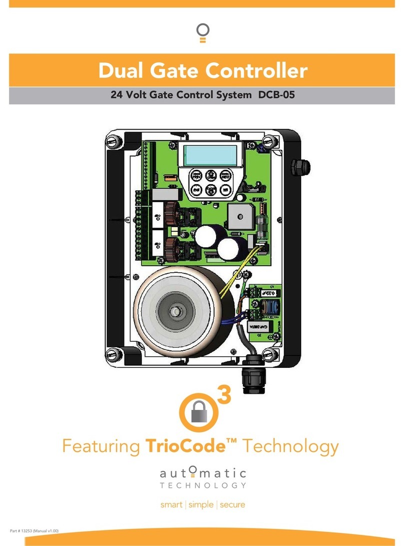
Automatic Technology CB-19 User manual

AUTOMATIC TECHNOLOGYAUSTRALIA PTY LTD
OWNERS COPY Warning: Failure to comply with the
installation instructions and the
safety warnings may result in
serious personal injury and/or
property, opener or controller damage.
Installation Instructions
CB-19 AUTOMATIC DUAL GATE
CONTROLLER
PN 13252

GARAGE DOOR OPENERS | GATE OPENERS | REMOTE CONTROL ACCESS SOLUTIONS

Automatic Technology Australia Pty Ltd to the extent that such may be lawfully excluded hereby expressly disclaims all
conditions or warranties, statutory or otherwise which may be implied by laws as conditions or warranties of purchase of an
Automatic Technology Australia Pty Ltd Sliding Gate Opener and Automatic Technology Australia Pty Ltd hereby
further expressly excludes all or any liability for any injury, damage, cost, expense or claim whatsoever suffered by any
person as a result whether directly or indirectly from failure to install the Automatic Technology Australia Sliding Gate
Opener in accordance with these installation instructions.
CONTENTS
PAGE CONTENTS
3 FEATURES
4 CONTROL BOARD LAYOUT
5 MENU STRUCTURE
6 INITIAL ELECTRICAL INSTALLATION
7 POWERING UP THE CONTROLLER
7 SETUP TRAVEL
7 LIMIT SWITCH / AMP TRAVEL SETUP
9 RE-PROFILING TRAVEL
10 SETTING TIMED TRAVEL
11 SETTING PEDESTRIAN POSITION
12 DESCRIPTION OF STANDARD OPERATION
13 CONTROL BOARD ADJUSTMENTS
13 MENU 2 CURRENT TRIPS
14 MENU 3 AUTO-CLOSE TIMES
14 MENU 4 LOCK TIMES
15 MENU 5 LIGHT TIMES
15 MENU 6 MOTOR SETTINGS
15 MENU 7 OPERATING MODES
17 PARAMETER VIEWING AND EDITING
18 TRANSMITTER OVERVIEW
18 BASIC CODE TRANSMITTER PROCEDURE
19 TRANSMITTER EDIT PROCEDURE
20 TRANSMITTER LIST MANAGEMENT
21 CODE OPERATION (LOCATION EMPTY)
21 CODE OPERATION (LOCATION USED)
21 DELETE OPERATION
21 EDIT OPERATION
21 COPY OPERATION
22 REMOTE CODE SET PROCEDURE
23 DIAGNOSTIC TOOLS (MENU 8)
23 MENU 8.1 TEST INPUTS
23 MENU 8.2 TEST TX’ERS
23 MENU 8.3 DISPLAY HISTORY
23 MENU 8.4 MEMORY USAGE
24 MENU 8.5 SERVICE COUNTER
24 MENU 8.6 COUNTERS
24 MEMORY TOOLS (MENU 9)
24 MENU 9.1 CLR CONTROL
24 MENU 9.2 CLR TX’ERS
25 SPECIFICATIONS
26 WARRANTY AND EXCLUSION OF LIABILITY

3
FEATURES
Your CB-19 controller has many features
which you will appreciate. The compo-
nents and materials used in this Automatic
gate controller are of the latest technology
and highest quality. Listed below are some
of the many features.
OPERATION
To operate the gate opener simply activate
one the integrated controller’s control
inputs using a remote control transmitter,
keypad or many other devices such as key
switches, loop detectors etc. In response
the gate will then open, stop or close as
requested. Optionally, the controller can be
configured to automatically close after
operation using one of several auto-close
modes.
OPERATOR CONSOLE
Incorporated into the CB-19 is a simple to
use operator console which consists of
several buttons and a display. The console
greatly simplifies installation, adjustments
and status indication. With the addition of
the console, facilities which were only
available on previous receivers using an
additional hand held programmer are now
available as standard via a simple menu
system. Features include editing
transmitter storage and names, setting
various parameters, selecting specialized
operating modes and preforming system
diagnostics.
HOPPING CODE TRANSMITTERS
The receiver incorporates a Hopping code
remote control receiver. Hopping code
systems work by the transmitters
generating a new encrypted access code
each time they are activated.As the receiv-
er is able to follow the encryption
sequence and also rejects any access code
it has already received it is able to foil code
breaking techniques used by thieves to
gain unauthorized access. In addition to
this, each hopping code transmitter has a
unique serial number - so no two
transmitters are alike. Further, with a huge
error rejection rate which allows less than
1 error in 1019 the security of the remote
control system is greatly enhanced.
SECURITY CODE STORE
The CB-19 uses state of the art technology
in storing your selected transmitter
security codes. Up to 511 different
transmitters can be stored in the memory
with the facility to assign a 11 character ID
label to each transmitter.
TRANSMITTER MANAGEMENT
FLEXIBILITY
Whenever a large number of transmitters
are used, managing those transmitter effec-
tively is of great importance. The CB-19
provides many feature which enhance
transmitter management. Transmitters can
be listed by store location, group number,
serial number or I.D label. Tools are avail-
able which allow transmitters to be
Replaced, Deleted and Edited. A quick
transmitter code set feature is provided
which allows the button functions of an
existing transmitter to be copied to all
transmitters to be coded. This feature
allows many transmitters to be coded with-
out the need for the installer to touch any
console buttons during the coding process.
When all transmitters are coded, a trans-
mitter storage report can be generated
which can be easily transferred to a P.C for
record keeping.Access logging can also be
implemented by enabling the generation of
a transmitter activity report each time the
receiver is triggered.
VARIOUS TYPES OF DRIVE UNITS
SUPPORTED.
The controller can be used with gate drive
units that use micro-switches, mechnical
stops or slip clutches. In addition to this
the micro-switch type drive units can be
wired using 3 or 5 wires.
EASE OF INSTALLATION
During installation the controller will
automatically detect the wiring type and
the number of motors connected. In addi-
tion the installer is guided through the
steps of installation by first adjusting the
travel limits (under motor power). This
can be done via the console keypad or via
a hand held transmitter (this allows the
installer to closely observe and control
the gates movement from any position
rather than having to be within arms
reach of the console). Once the limits
have been adjusted, the controller will
automatically learn the travel characteris-
tic of each gate.
STATUS INDICATION
The status of the gate controller can be
determined at anytime by observing the
console’s screen. When the MAIN
SCREEN is displayed, the current
position of the gate or the result of the last
movement can be viewed. The display will
also show the count down progress of the
auto-close timers. Any active input will
also be displayed along with the state of
various features such as periodic service,
vacation mode, etc.
PASSWORD PROTECTION
All operating parameters and transmitter
storage can be protected from being
changed by unauthorized personnel by an
optional password protection feature.
CONTROL OF LOCK AND LIGHTS
The incorporated controller has two pro-
grammable outputs which can be selected
to operate an electric lock and warning or
courtesy lights. The timing of these out-
puts can be adjusted to suit your needs. In
addition a button on a remote control can
be coded to operate the Light output.
EXTENSIVE OPERATING MODES
VIA CONTROL INPUTS AND
REMOTE CONTROL
The ontroller can be configured to operate
in many different ways via its 8 control
and safety inputs which include P.E,
OPEN, STOP, CLOSE, OSC, SWIPE and
PEDESTRIAN. Remote control operation
is provided with each transmitter’s button
being able to be configured to operate one
of OSC, PEDESTRIAN, SWIPE, CLOSE,
OPEN, STOP, LIGHT or VACATION
functions. The controllers functionality is
further enhanced by 4 auto-close modes, 4
P.E response modes and two pedestrian
response modes. For details refer to
relevant instruction manual sections.
BATTERY BACKUP AND SOLAR
OPERATION
TheAutomatic gate controller can be fitted
with optional battery backup or solar
chargers to provide operation during
power outages or at unpowered sites
respectively.
4
CONTROL BOARD LAYOUT
1 Aux control input
2 P.E N/C input terminal (remove 25 when used)
3 OPN N/O input terminal
4 STP N/O input terminal
5 CLS N/O input terminal
6 OSC N/O input terminal
7 SWP N/O input terminal
8 PED N/O input terminal
9 COM terminal for input terminals 1 to 8
10 OUTPUT 2 (optional relay module coil drive
output)
11 OUTPUT 1 N/C relay contact
12 OUTPUT 1 COM relay contact
13 OUTPUT 1 N/O relay contact
14 MOTOR 2 terminal 1
15 MOTOR 2 terminal 2
16 MOTOR 2 close limit switch input terminal
17 MOTOR 2 open limit switch input terminal
18 COM terminal for Terminals 16,17,19 & 20.
19 MOTOR 1 close limit switch input terminal
20 MOTOR 1 open limit switch input terminal
21 MOTOR 1 terminal 1
22 MOTOR 1 terminal 2
23&24 24VDC output for powering accessories
25 PE input jumper (remove when 2 is used)
26 Standby battery / solar charger connector
27 Mains Earth connection
28 24VAC power input (from transformer)
29 Console keypad
30 Console display (LCD)
31 Antenna connector
AA..TT..AA
CCBB1199
FFiirrmmwwaarree
##..####
1
2
3
4
5
6
7
8
9
10
11
12
13
14
15
16
17
18
19
20
21
22
23
24
26
28
27
31
29
30
25
Com

MENU STRUCTURE
5
MENU 8
Diagnostics
MENU 9
Memory Tools
MENU 10
Setup Travel
MENU 1
Code Transmitter
MENU 2
Current Trips
MENU 3
Auto-Close Times
MENU 10.2
Timed Travel
MENU 10.3
Reprofile Travel
MENU 9.1
CLR Control.
See Page 24
MENU 9.2
CLR Tx’ers.
See Page 24.
MENU 8.1
Test Inputs
MENU 8.2
Test Tx’ers
MENU 8.3
Display History
MENU 8.4
Memory Usage
MENU 8.5
Service Counter
MENU 4
Lock Times
MENU 5
Light Times
MENU 6
Motor Settings
MENU 7
Operating Modes
MAIN SCREEN
(Gate Status
& Information)
Code/Edit
Transmitter
Procedure.
See Page 18.
Parameter List
1. Margin 1
...etc
See Page 13.
Parameter List
1. STD Autoclose
2. P.E. Autoclose
3.
Ped’n Autoclose
4. P.E.
Ped’n
Autoclose
...etc
See Page 14.
Timed Travel
Setup Procedure.
See Page 10.
Travel Reprofile
See Page 9.
Control Input
Status Display.
See Page 23.
Transmitter
Testing
See Page 23.
Event History
Display.
See Page 23.
Memory Usage
See Page 23.
Periodic Service
Cycle Counter
See Page 24.
Parameter List
1. Open Lock Time
2. Close Lock Time
3. Pre-Opn Lock Time
4. Pre-Cls Lock Time.
See Page 14.
Parameter List
1.OnAfterCycleTime
2.OnBeforeOpnTime
3. On BeforeCls Time
See Page 15.
Parameter List
1. CLS Sync Delay
2. OPN Sync Delay
3. Open Speed
4. Close Speed
....
etc
See Page 15.
Parameter List
1. PE Input Response
2. Ped Input Response
3. Remote Code Enable
4. Activity Report
...etc
See Page 15.
Notes
1. Move Left/right using PREV/NEXT Buttons.
2. Move Up/Down using EXIT/SET Buttons.
3. System will automatically return to the main screen after 30
secs if a menu screen is displayed and no buttons are pressed.
4. Pressing EXIT when in MENU 1 - MENU 10 will return to
MAIN SCREEN.
MENU 8.6
Counters
Cycle and event
Counters
See Page 24.
MENU 10.1
Limit/Amp Travel
Travel Limit
Setup Procedure.
See Page 7.
MENU 10.4
Set Pedestrian
Ped’n Position
Setup Procedure
See Page 11.

INITIAL ELECTRICAL INSTALLATION
CAUTION:
CABLES WHICH HAVE A GREEN / YELLOW COLOURED INSULATION
ARE FOR EARTHING PURPOSES ONLY. NEVER USE THESE CABLES FOR ANY OTHER PURPOSE.
STEP 1.WIRING MOTORS AND LIMITS SWITCHES
The CB-19 can be connected to the gate drive units in one of sev-
eral ways. The figures below show the various wiring methods
used for different drive unit types. Select the appropriate method
for your drive unit. Note “non-motor current carrying limit-
switch” type drive units can be connected using the standard 5
wire connections or a special 3 wire method that uses a single
limit switch sense wire and two diodes. If two drive units are
used, repeat the wiring for the second motor using the MOTOR 2
terminals. Note the drive unit connected to the MOTOR 1 termi-
nals will open first and will be used for pedrestrian access. The
motor travel direction can be reversed by swapping the motor
connections. An opportunity to confirm the correct motor polari-
ty is provided during the limit setup proceedure.
STEP 2.INSTALLING ANTENNA
Mount the antenna at the highest available position for optimal
reception. Connect the signal and ground wires of the antenna
coaxial cable to the CB-19’s antenna connector. Do not cut the
coaxial cable.
STEP 3.WIRING CONTROL SWITCH INPUTS
When remote control operation is only required the CB-19’s con-
trol switch inputs are not utilised. It is, however, strongly advised
that a Photo-electric Safety Beam be used to prevent the gate
being driven closed when an object is present in the gate way. The
other console switch inputs may be used for operating the gate via
any device that provides and switch contact output. The figure
below shows how to connect a Photo-electric Beam to the CB-19.
Note the P.E LINK jumper must be removed when the PE input is
used. The figure also shows the connections for a switch connect-
ed to the OSC control input.
STEP 4.WIRING OUTPUT1 AND OUTPUT2
Outputs 1 and 2 are used to control a lock and a light. Which out-
put is to control which function and the way it is controlled is pro-
grammable. If using these outputs make sure that the functions
are configured for correct operation prior to setting the trav-
el limits. OUTPUT1 is a relay output with high current capabili-
ty. OUTPUT2 is used to activate an optional external relay mod-
ule (RO-1) which in turn is used to switch the load (see figure
below).
M1
OPEN
CLOSE
M1
OPEN
CLOSE
1N4004 Diodes
Limit Switch Drive Unit Using 5 Wires
Limit Switch Drive Unit Using Special 3 Wire Method
M1
Mechnical Stop and Slip Clutch Drive Units
6
Wiring Control Switch Inputs
TRANSMITTER
Power input
output
RECEIVER
Power input Photo-electric Beam
Connection of RO-1 to OUTPUT 2
Remove Link
RO1-101

POWERING UP THE CONTROLLER
After checking the initial wiring, apply power to the CB-19. The
controller will go through a startup sequence displaying the
STARTUP SCREEN which indicates the controller type and
firmware version. After a short delay the MAIN SCREEN will be
displayed. If this is the first time the controller has been used, the
MAIN SCREEN should indicate that the limits are not set. If the
display shows that some input is active then rectify the situation
before proceeding. If a default setting is to be changed it should
be done now beforing setting the travel limits.
A.T.A
CB19
Firmware
#.##
STARTUP SCREEN
7
SETUP TRAVEL
This section shows how to set the travel limits for drive units with limit switches. The procedure can be partly completed using
a remote control transmitter as a remote console. In order to use a remote control transmitter it must first have at least one of
its buttons coded to the controller’s receiver. The function assigned to the transmitter's buttons is of no concern here as the
buttons are temporally assigned to OPEN, CLOSE and SET. Refer to TRANSMITTER OVERVIEW.
Note: The limit setting procedure can be aborted at anytime by pressing EXIT.
STEP 1.NAVIGATING TO “LIMIT/AMP TRAVEL MENU”
To navigate to the Menu 10.1 from the MAIN SCREEN simply
press PREVto display MENU 10, followed by SET to display
MENU 10.1. Press SET again to start the limit setting procedure
STEP 2.CONFIRMING READY TO START.
The CB-19 will prompt you to confirm that the motor wiring is
complete and that the gate(s) are in a halfway position and
engaged. Press SET to confirm.
The CB-19 can be used with drive units that use different methods to stop at the end of their travel.
The types supported are:
A) Limit switch. Open and close limit switches indicate to the controller when the travel limit is reached.
B) AMP trip limits. Travel limits are detected by and an increase in motor current as mechnical stops are reached.
C) Timing. The motor is driven for a preset time. When the travel limit is reached a clutch incorporated into the drive
unit allows the motor to keep turning for the remaining preset running time.
The setup proceedure for each type of drive unit follow.
LIMIT SWITCH / AMP TRAVEL SETUP
MENU
10.1
Limit/AMP
Travel
PRESS
Selecting Limit/AMP Travel Setup
PRESS
Confirming Wiring Is Completed
PRESS
Selecting Limit/AMP Travel Setup
Motor
Wiring
Completed?
Half
Open
Gate
&
Engage
Mtrs,
SET
MAIN SCREEN
Limits
Not
Set!
PPrreessss
<<>>
ttoo
AAcccceessss
MMEENNUUSS

LIMIT SWITCH / AMP TRAVEL SETUP (cont)
STEP 3. CONFIRMING CORRECT WIRING DETECTED
The controller will now automatically detect the type of drive unit
used by the number of wires used. If the correct number of wires
is displayed then press SET to continue otherwise press EXIT and
check the wiring.
Continue from STEP 4A for 2WIRE (AMP TRAVEL) Setup.
STEP 4. CONFIRMING MOTORS DETECTED.
The controller will now automatically detect if one or two motor
are connected. If the correct number is displayed then press SET
to confirm otherwise press EXIT and check the wiring.
STEP 5. ADJUSTING CLOSE LIMIT(S).
The controller will now prompt for the motor(s) to be driven to the
desired close limit and for the limit switches to be adjusted so that
the motor stops at the desired position. The motor can be driven
using the UP and DOWN buttons on the console keypad or Button
1 and 4 of a transmitter. After making adjustments to the limit
switch positions always re-approach the limit at full speed by
driving the motor open a short distance and then driving it close
again. When the close limit has been adjusted press SET to con-
tinue. Note: If the motor drives in the wrong direction (UP closes
gate / DOWN opens gate) the motor wires need to be swapped.
STEP 6. ADJUSTING OPEN LIMIT(S).
The controller will now prompt for the motor(s) to be driven to the
desired open limit and for the limit switches to be adjusted so that
the motor stops at the desired position. The motor can be driven
using the UP and DOWN buttons on the console keypad or Button
1 and 4 of a transmitter. After making adjustments to the limit
switch positions always re-approach the limit at full speed by
driving the motor close a short distance and then driving it open
again. When the open limit has been adjusted press SET.
STEP 7. AUTOMATIC PROFILING
After a brief pause the controller will automatically close and
open gate several times and learn the gates load and travel
characteristics. When the setup is complete the MAIN SCREEN
will be displayed with the gate shown to be OPEN. The Gate can
now be used.
//\\\\//
M1(2)&
Adjust
CLOSE
Limit,
SET
PRESS
Adjusting The CLOSE LIMIT
OR
PRESS
8
PRESS
Confirming Detected Motor Wiring
Motor
=2/3/5
Wire
Press
SET
if
OK
PRESS
Confirming Detected Motor Wiring
M1&2
Detected|
Press
SET
if
Ok.
//\\\\//
M1(2)&
Adjust
OPEN
Limit,
SET
PRESS
Adjusting The OPEN LIMIT
OR
PRESS
AMP TRAVEL SETUP (Step 4A)
STEP 4A. SELECTING THE NUMBER OF MOTORS.
The controller will now prompt for the number of motors con- nected to be entered. Use the UP or DOWN key to select the cor-
rect number and then press SET.
STEP 5A. TEST AND ADJUST STOP DETECTION CUR-
RENT TRIP LEVELS.
Note: If a dual gate installation is being used, steps 5A and 6A
will be undertaken for motor 2 and then motor 1.
For this type of installation the controller detects the travel limits
by sensing a motor current trip when the mechanical stop is
reached.. In this step, the stop detection current trip levels for each
motor are tested and adjustments made to obtain the optimum
level. A high value results in undue force, while a low value will
result in the gate stopping midway due to variations in friction etc.
continued...
PRESS
Selecting Number Of Motors Used
Select
Number
of
Motors
1
1

AMP TRAVEL SETUP (cont)
STEP 5A. (cont)
Using the Up / DOWN keys drive the motor into the close and
open stops and adjust the stop curent trip levels. The motor should
be driven into each mechincal stop at full speed until the con-
troller senses a current trip and stops the motor.
Note: If the motor drives in the wrong direction (UP closes gate
/ DOWN opens gate) the motor wires need to be swapped over.
The trip current for each direction can be view and adjusted by
pressing the NEXT key on the keypad.
See PARAMETER VIEWAND EDIT for adjustement procedure.
STEP 6A. CONFIRMING SETTINGS
When the settings have being adjusted correctly, drive the gate to
the open stop and then press the SET Key.
As step 7A requires the gate to be open, the controller will pro-
mopt you to confirm the gate leaf is in the open position. Press
SET to confirm or press EXIT to go back and drive the gate open.
STEP 7A. AUTOMATIC PROFILING
After a brief pause the controller will automatically close and
open gate several times and learn the gates load and travel
characteristics. When the setup is complete the MAIN SCREEN
will be displayed with the gate shown to be OPEN. The Gate can
now be used.
//\\\\//
M1(2)
to
Test
Stop
AMPS,
SET
PRESS
Testing The Stop Detection Settings
OR
PRESS
PRESS
PRESS
PRESS
Accessing the Stop Detection Settings
Press
>
to
Adjust
Stop
AMPS
Stop Detection Settings
M1(2) OPN(CLS)
Limit
AMPS
2.0
//\\\\//
M1(2)
to
Test
Stop
AMPS,
SET
PRESS
Confiming Stop Current trip settings
OR
PRESS
9
PRESS
Confirming Gate is Open
At
Open
Limit?
Press
SET
if
ok.
Reprofiling is a simplified way of re-learning the travel charastics of a previously setup Limit Switch/AMP travel installation. Re-pro-
filing can be used when the travel limits of a gate are altered or when the travel characteristics of the gate change due to mechnical
adjustments etc. To initiate a re-profile simply locate “MENU 10.3 Reprofile Travel” and press SET then follow the prompts. The
reprofile feature will also be automatically started when a control parameter is altered which affects the gates travel. Reprofile is not
avaiable for TIMED TRAVEL installations.
RE-PROFILING TRAVEL

10
SETTING TIMED TRAVEL
STEP 1.NAVIGATING TO “TIMED TRAVEL MENU”
To navigate to the Menu 10.2 from the MAIN SCREEN simply
press PREV, SET then NEXT. Press SET to start the setup.
STEP 2.CONFIRMING READY TO START.
The CB-19 will prompt you to confirm that the motor wiring is
complete. Press SET to continue.
The controller will now prompt you to confirm that you under-
stand that no current trip obstruction detection is available
when using timed travel. Press SET if you accept this.
STEP 3. SELECTING THE NUMBER OF MOTORS.
The controller will now prompt for the number of motors to be
entered. Use the UP or DOWN key to select the correct number
and then press SET.
STEP 4. SELECTING SETUP METHOD.
The controller will now prompt for the setup procedure to be
selected. Press SET to set the travel times by actually driving the
motor(s) or press EXIT to enter exact time parameters. Continue
with STEP 5 if “DRIVE MOTORS” is selected or go to STEP 5A
if “ENTER TIMES” is selected.
This section shows how to set the travel times when using drive units with slip clutches etc. Two methods are available for set-
ting up the travel times. The first allows the installer to drive the motor(s) so that the actual travel time can be recorded. The
second allows exact times to be entered. Note: The limit setting procedure can be aborted at anytime by pressing EXIT.
MENU
10.2
Timed
Travel
PRESS
Selecting Timed Travel Setup
Selecting Install Method
PRESS
Confirming Obstruction Detection is Disabled
SET=Drive
Motors
EXIT=Enter
times
Current
Trips
Are
DISABLED
OK?
PRESS
Confirming Wiring Is Completed
Motor
Wiring
Completed?
STEP 5. ADJUSTING GATE LEAF SYNCHRONIZING
DELAYS. (Dual gate installations only)
For dual gate installations, the controller will prompt for you to
edit the gate leaf synchronizing delays. The settings are used to
introduce a delay between when the motors start so that overlap-
ping gates are opened and closed in the correct order. Press EXIT
to continue with STEP 6 or press SET to access the gate leaf syn-
chronizing delay parameters. See PARAMETER VIEW AND
EDIT for adjustement procedure.
STEP 6. CONFIRMING GATE IS OPEN.
The controller will now prompt for you to comfirm that the gate
is open. If the gate is open press SET and continue with STEP 7.
SETTING TIMED TRAVEL - DRIVE MOTORS
Edit
Gate
Sync
Delays?
PRESS
Selecting to Edit Synchronizing Delay Times
Is
Gate
Open?
PRESS
Confirming Gate is Open

11
Press EXIT if the gate is not open and the controller will now
prompt for the gate to be opened by holding the UP key. When the
UP key is released the motor(s) will stop and STEP 6 restarted.
Note: If the motor drives in the wrong direction the motor wiring
needs to be swapped.
STEP 7. SETTING CLOSE CYCLE DRIVE TIME.
The controller is now ready for the close cycle drive time to be set.
To do this simply press and hold the DOWN key until the gate is
driven fully closed. Note: If the motor drives in the wrong direc-
tion the motor wiring needs to be swapped.
STEP 8. SETTING OPEN CYCLE DRIVE TIME.
The controller is now ready for the open cycle drive time to be set.
To do this simply press and hold the UP key until the gate is driv-
en fully open.
STEP 9. CONFIRMING SETTINGS.
The controller will now prompt you to save the settings. Press
EXIT to restart from STEP 6 or, if you are happy with the settings
press SET and the main screen with be displayed and the gate is
ready to be used.
SETTING TIMED TRAVEL - DRIVE MOTORS (cont)
Hold
//\\
until
gates
Are
Open!
PRESS
Opening Gate in Preparation For Setting Travel Times
Hold
\\//
to
set
close
cycle
time
PRESS
Setting Close Cycle Time
Hold
//\\
to
set
open
cycle
time
PRESS
Setting Open Cycle Time
Save
Settings?
PRESS
Confirming Settings
SETTING TIMED TRAVEL - ENTER TIMES
STEP 5A. ENTERING TIMED TRAVEL PARAMETERS.
When the ENTER TIMES method is selected a list of parameters
is provided to configure the gates travel. The parameters provid-
ed are listed below with a brief discription.
M1 Normal Open Time -Sets Open drive time for M1
M1 Normal Close Time -Sets Close drive time for M1
M2 Normal Open Time -Sets Open drive time for M2*
M2 Normal Close Time -Sets Close drive time for M2*
Close Sync Delay -Sets Delay before M1 is started on
close cycles*
Open Sync Delay -Sets Delay before M2 is started on
open cycles*
*Only used for dual gate installations.
Once the parameter values have be set press EXIT and the main
screen is displayed and the gate is ready for use.
SETTING PEDESTRIAN ACCESS POSITION
The controller can be instructed, via its pedestrain control feature,
to partly open and provide pedestrian access but prevent vechilar
access. This is acheived by partly opening the motor 1 gate leaf.
If daul motors are used, motor 2’s gate leaf is held closed. The
partly open position of motor 1’s gate leaf is initally set to a posi-
tion halfway between open and closed. This initail position can be
adjusted by the installer to any postion within the gates travel
range by selecting a pedestrian access travel time (from closed).
The setting is accessed from “MENU 10.4 Set Pedestrian”. The
time is adjustable in 1 second steps.

DESCRIPTION OF STANDARD OPERATION
This section describes the standard operation of the control board
with the factory set default values.
MOTOR CONTROL.
The controller drives the motor in the appropriate direction as
instructed by the control inputs. Once a cycle is started the motor
will continue to travel until:
1.The controller is instructed to stop by a control input.
2.The motor's travel limit is reached.
3.The motor is obstructed, overloaded or stalls
When the control inputs instruct the control board to change the
motor direction, the controller brakes the motor, waits for the
motor to stop and then starts the motor in the other direction.
MOTOR OBSTRUCTION DETECTION (only supported
with limit switch type drive units)
If a motor is obstructed while opening, the motor is stopped. If the
motor is obstructed while closing, the motor is stopped and then
reversed to the open position. Obstruction detection is achieved
by monitoring the motor's curent and comparing it to the “nor-
mal” current profile for the motor. If the current of the motor rises
above the “normal” by the MARGIN AMP setting, then the motor
is said to be obstructed. In addition to the normal motor obstruc-
tion detection, motor overload and stall detection is provided to
protect the gate opener and controller.
MOTOR SPEED CONTROL
The motor's speed is controlled by varying the voltage applied to
the motor. When the motor is started its voltage in ramped up to
the OPEN or CLOSE Speed Voltage parameter. When the limit
switch of a drive unit is activated the motor is braked so as to
come to a rapid but gentle stop.
LOCK RELEASE OUTPUT
The lock release output is configured to pulse for 0.5 seconds at
the start of each cycle. The output is turned on at the same time
the motors are started. The output is provided on OUTPUT1.
COURTESY LIGHT
The courtesy light is normally used to illuminate the driveway etc.
The light will be turned on each time the gate is activated (day or
night) and automatically turned off 1 minute after the drive cycle
has finished. The light can also be activated and deactivated by
pressing a transmitter button assigned the LGT function. The light
output is provided on OUTPUT2 (requires additional light relay
module RO-1).
OPEN / STOP / CLOSE (OSC) INPUT
(Activated by OSC terminal with N/O switch or by transmitter
button with OSC function assigned)
If the gate is stopped the OSC input will cause the gate to move
in the opposite direction to that last travelled. If the gate is mov-
ing the OSC input will cause the gate to stop.
PEDESTRIAN ACCESS (PED) FUNCTION
(Activated by PED terminal with N/O switch or by transmitter
button with PED Function assigned)
The pedestrian access operation partly opens the gate to allow
pedestrian access but prevent vehicle access. The position the gate
leaf is driven to is automatically set to halfway during setting of
the travel limits, but can be manually selected. Pedestrian access
mode is entered when the input is activated and the gate is in the
closed position. If the gate is not in the pedestrian access mode,
the PED input will stop the gates if moving, or close the gates, if
stopped. While in pedestrian access mode, the pedestrian access
position temporally becomes the open limit for the gate leaf. The
PED input then acts with an OSC type function. The pedestrian
access mode is exited when the gate is closed or when another
input is activated.
CLOSE (CLS) INPUT
(Activated by CLS terminal with N/O switch, by transmitter but-
ton with CLS function assigned or by console’s DOWN button)
Activating the CLS input will cause the gate to close. Holding the
input active will prevent opening.
SWIPE (SWP) INPUT
(Activated by SWP terminal with N/O switch or by transmitter
button with SWP function assigned)
Activating the the SWP input will cause the gate to be opened. If
the terminal input is held it will prevent the gate being closed. The
swipe input also effects P.E TRIGGERED AUTO CLOSE.
OPEN (OPN) INPUT
(Activated by OPN terminal with N/O switch, by transmitter
button with OPN function assigned or by console’s UP button)
Activating the OPN input will cause the gate to open. Holding the
input will prevent closing.
STOP (STP) INPUT
(Activated by STP terminal with N/O switch, by transmitter
button with STP function assigned or by console’s EXIT button)
Activating the STP input while the gate is moving will cause the
gate to be stopped. If the STP terminal is held it will prevent the
gate from being moved.
PHOTOELECTRIC SAFETY BEAM (P.E) INPUT
(Activated by PE terminal with N/C switch)
When the P.E input is active, the gate is prevented from being
closed. If the P.E input is triggered while the gate is closing, the
controller will stop the motors and then open the gate. The P.E
input has no effect while the gate is opening.
VACATION MODE
The controller supports a vacation mode where remote control
access is disabled. The mode is activated by pressing a
transmitter button with the VAC function assigned until the con-
sole displays that vacation mode is enabled (approx. 5 seconds).
When activated any transmitter button which is assigned VAC
will be ignored. To turn the Vacation mode off simple press a
transmitter button with the VAC function assigned (Only requires
a brief activation.) Vacation mode can also be turned on or off
manually by editing the VACATION MODE parameter.
12

13
CONTROL BOARD ADJUSTMENTS
The control board’s standard operation is altered by editing various control parameters. This section describes the parameters
and the effect they have. Use the PARAMETER VIEWING AND EDITING PROCEDURE to access the parameters.
MENU 2 CURRENT TRIPS
The current trip parameters available depends on the type of drive unit used in the installation. The tables below show the parameters
grouped by installation type.
PARAMETER (LIMIT SWITCH) MIN MAX DEFAULT STEP UNITS MENU #
MARGIN 1 AMPS
Sets Motor 1 obstruction detection margin 0.0 2.0 0.5 0.1 AMPS 2
MARGIN 2 AMPS
Sets Motor 2 obstruction detection margin 0.0 2.0 0.5 0.1 AMPS 2
MAX STARTUP AMPS
Sets maximum permitted starting current of motors 0.0 10.0 10.0 0.1 AMPS 2
PROFILING
Enables Motor Current VS Drive Time profiling OFF ON ON 2
CUTOUT AMPS
Maximum motor current permitted after startup 0.0 10.0 10.0 0.1 AMPS 2
SETTLE TIME
Motor startup time during which MAX STARTUP
AMPS applies 0.1 25.5 1.0 0.1 SEC 2
AMP TRIP LIMIT
Motor drive electronics current limit 0 13 13 1 AMPS 2
PARAMETER (AMP LIMITS) MIN MAX DEFAULT STEP UNITS MENU #
MOTOR 1 OPEN LIMIT AMPS
Sets Motor 1 open limit detection current 0.0 5.0 2.0 0.1 AMPS 2
MOTOR 1 CLOSE LIMIT AMPS
Sets Motor 1 close limit detection current 0.0 5.0 2.0 0.1 AMPS 2
MOTOR 2 OPEN LIMIT AMPS
Sets Motor 2 open limit detection current 0.0 5.0 2.0 0.1 AMPS 2
MOTOR 2 CLOSE LIMIT AMPS
Sets Motor 2 close limit detection current 0.0 5.0 2.0 0.1 AMPS 2
MAX STARTUP AMPS
Sets maximum permitted starting current of motors 0.0 6.0 5.0 0.1 AMPS 2
SETTLE TIME
Motor startup time during which MAX STARTUP
AMPS applies 0.1 25.5 1.0 0.1 SEC 2
AMP TRIP LIMIT
Motor drive electronics current limit 0 13 13 1 AMPS 2
PARAMETER (TIMED TRAVEL) MIN MAX DEFAULT STEP UNITS MENU #
CUTOUT AMPS
Maximum motor current permitted after startup 0.0 10.0 10.0 0.1 AMPS 2
MAX STARTUP AMPS
Sets maximum permitted starting current of motors 0.0 6.0 5.0 0.1 AMPS 2
SETTLE TIME
Motor startup time during which MAX STARTUP
AMPS applies 0.1 25.5 1.0 0.1 SEC 2
AMP TRIP LIMIT
Motor drive electronics current limit 0 13 13 1 AMPS 2

MENU 3 AUTO-CLOSE TIMES
STANDARD AUTO-CLOSE
This mode is selected by entering a non-zero time for the STD
Autoclose parameter. When selected the gate will auto-close after
being fully opened (except when the gate has reversed to the open
position after a motor obstruction or overload). Countdown is
suspended by the P.E, OPN or SWP input being active. The count-
down is aborted if the STP input is activated. The countdown will
restart if the gate is open and OPN or SWP is activated.
P.E TRIGGERED AUTO-CLOSE
This mode is selected by entering a non-zero time for the “P.E
Autoclose” parameter. This mode is used to auto-close the gate
but only after a vehicle has passed through the gateway and
triggered the P.E input. The swipe input can be used to clear the
P.E triggered status so that the P.E input must be activated again
before the countdown will start. As with the other P.E modes the
STP input will abort countdown and the OPN and SWP inputs
will restart the countdown if the gate is OPEN.
PEDESTRIAN ACCESS AUTO-CLOSE
This mode is selected by entering a non-zero time for the “Ped’n
A/C” parameter. When selected the gate will auto-close after
being opened for pedestrian access unless it was following a
reverse from an obstruction.
P.E TRIGGERED PEDESTRIAN AUTO-CLOSE
This mode is selected by entering a non-zero time for the “P.E
Ped’n A/C” parameter. This mode is the same as the P.E
triggered auto-close mode but it only operates during pedestrian
access. As the SWP input is not available during pedestrian
access, the PED input can be configured to act in a SWP mode by
setting the “PED I/P = PED SWIPE MODE” parameter to ON.
AUTO-CLOSE AFTER OBSTRUCTION
Two parameters are provided to enable the auto-close feature to
be activated after obstructions. Normally the auto-close feature is
not enabled after obstructions for safety reasons.AP.E beam must
be used for these features to be activated.
AUTO-CLOSE AFTER POWER UP
Auto-close after power up is normally not enabled for safety rea-
sons but can be enabled if desired by setting this parameter to ON.
The auto-close modes automatically close the gate after it has been operated. To implement this, the controller starts a timer
once the gate has reached its desired open position. The timer then counts down and when it expires the controller starts to
close the gate. Details about the four auto-close modes follow.
CONTROL BOARD ADJUSTMENTS (cont)
14
PARAMETER MIN MAX DEFAULT STEP UNITS MENU #
STD AUTOCLOSE TIME
Sets and enables the standard auto-close time. 0.0 300.0 0.0 1.0 SEC 3
P.E AUTOCLOSE TIME
Sets and enables the P.E triggered auto-close time. 0.0 60.0 0.0 1.0 SEC 3
PEDESTRIAN AUTOCLOSE TIME
Sets and enables the Pedestrian auto-close time. 0.0 60.0 0.0 1.0 SEC 3
P.E PEDESTRIAN AUTOCLOSE TIME
Sets and enables the PE Pedestrian auto-close time 0.0 60.0 0.0 1.0 SEC 3
AUTOCLOSE AFTER CLOSE OBSTRUCTION
Enables autoclose feature after close obstructions OFF ON OFF 3
AUTOCLOSE AFTER OPEN OBSTRUCTION
Enables autoclose feature after open obstructions OFF ON OFF 3
AUTOCLOSE AFTER POWER UP
Enabled auto-close after power up OFF ON OFF 3
MENU 4 LOCK TIMES
The control board’s lock function can be programmed for both
hold and pulse operation. The lock output can also be pro-
grammed to activate prior to the motor starting. The open cycle
and close cycle actions can be programmed differently. The lock
can be either OUTPUT1 or OUTPUT2 (see OPERATING
MODES).
PARAMETER MIN MAX DEFAULT STEP UNITS MENU #
OPEN LOCK TIME
Set the time the lock is activated for on open cycles 0.0 HOLD 0.5 0.1 SEC 4
CLOSE LOCK TIME
Set the time the lock is activated for on close cycles 0.0 HOLD 0.5 0.1 SEC 4
PRE-OPEN LOCK TIME
Time the lock is activated for prior to opening. 0.0 25.5 0.0 0.1 SEC 4
PRE-CLOSE LOCK TIME
Time the lock is activated for prior to closing 0.0 25.5 0.0 0.1 SEC 4

15
CONTROL BOARD ADJUSTMENTS (cont)
The motor settings adjust various aspects of the gate travel. When
a single gate installation is used the SYNC DELAY TIMES and
M2 settings are ignored. The default value for the CLOSE SYNC
DELAY time is automatically calculated for LIMIT
SWITCH/AMP TRAVEL installations. The value calculated is
selected so that the delay between M2 and M1 reaching the close
position is equal to the OPEN SYNC DELAY TIME. The MAX
OVERRUN TIME is set to 0 for TIMED TRAVEL installations.
MENU 5 LIGHT TIMES
MENU 6 MOTOR SETTINGS
The control board’s light function can be programmed to operate
a courtesy light or a warning light. The time the light stays on for
after a cycle is adjustable. The light can also be activated prior to
the gate moving so that a warning can be given of the pending
movement.g. Note the light outoput can be selected to be either
OUTPUT1 or OUTPUT2. The parameters are shown below.
MENU 7 OPERATING MODES
P.E INPUT RESPONSE MODE
The P.E input can be configured to respond in one of three modes.
OPEN AND CLOSE CYCLES STOP - In this mode all
cycles are prevented from being completed or initiated when the
P.E input is active.
CLOSE CYCLES STOP - In this mode the P.E input has
no effect when opening but will stop the gate when closing.
REVERSES CLOSE CYCLES - In this mode the P.E
input has no effect when opening but will cause the gate to reverse
if activated when closing.
PED INPUT FUNCTION
The PED input can be configured to a SWIPE type input for
pedestrian access. This provides full functionality with the P.E
Triggered Pedestrian auto-close function.
REMOTE CODE
The controller supports the Remote Code Set feature. This
parameter can be used to disable the feature for security or
transmitter management reasons.
ACTIVITY REPORTS & ACTIVITY REPORT ID
This parameter selects an activity report output. The ID number
is used to select the ID of the controller. Contact ATA for more
details
PARAMETER MIN MAX DEFAULT STEP UNITS MENU #
CLOSE SYNC DELAY TIME
Time delay between M2 and M1 closing 0.0 25.5 Auto (2.0) 0.1 SEC 6
OPEN SYNC DELAY TIME
Time delay between M1 and M2 opening 0.0 25.5 2.0 0.1 SEC 6
OPEN SPEED VOLTS
Voltage applied to motors when opening 12 24 22 1 VOLTS 6
CLOSE SPEED VOLTS
Voltage applied to motors when closing 12 24 20 1 VOLTS 6
STOP PAUSE TIME
Pause time used between motor direction changes 0.0 2.0 0.2 0.1 SEC 6
M1 NORMAL OPEN TIME
Normal open time for motor 1 0.0 60.0 0.0 0.1 SEC 6
M1 NORMAL CLOSE TIME
Normal close time for motor 1 0.0 60.0 0.0 0.1 SEC 6
M2 NORMAL OPEN TIME
Normal open time for motor 2 0.0 60.0 0.0 0.1 SEC 6
M2 NORMAL CLOSE TIME
Normal close time for motor 2 0.0 60.0 0.0 0.1 SEC 6
MAX OVERRUN TIME
Extra time allowed for cycle to complete (beyond
normal cycle time) 0 60 5 (0) 1 SEC 6
PARAMETER MIN MAX DEFAULT STEP UNITS MENU #
ON AFTER CYCLE LIGHT TIME
Time light remains on for after a cycle 0 255 60 1 SEC 5
ON BEFORE OPEN CYCLE LIGHT TIME
Minimum time light is activated for prior to opening 0 255 0 1 SEC 5
ON BEFORE CLOSE CYCLE LIGHT TIME
Minimum time light is activated for prior to closing 0 25.5 0 1 SEC 5

16
CONTROL BOARD ADJUSTMENTS (cont)
MENU 7 OPERATING MODES (cont)
VACATION MODE
Vacation mode can be turned on or off using this parameter.
BATTERY / SOLAR MODE
The controller can be instructed to turn off the battery backup
facilities so that the control board can be shut down without hav-
ing to disconnect the battery backup system.
PASSWORD PROTECTION
The password feature enables all parameters and configuration
settings to be protected unless a password is entered. When this
feature is turned on the user is requested to enter the desired pass-
word to be used. The password protection feature has a timeout
that expires after 60 seconds of inactivity. Alternately the user
may log out manually by pressing exit when the main screen is
displayed.
TRANSMITTER # GROUPING
The transmitter store number display format can be changed to
show a grouped format. When grouping is selected, instead of dis-
playing the store location as a number between 1 and 511, it is dis-
played as ##$ where ## is the group number and $ is a character
a,b,c,d,e,f,g or h which indicates the group member.
OPEN AND STOP INPUT POLARITY
The OPN and STP inputs are normally configured for N/O oper-
ation. These parameters allows the input’s operation to be
changed to N/C.
OUTPUT 1 & 2 FUNCTION
This parameter selects functions assigned to OUTPUTS 1 & 2.
EZYPLOT MOTOR
This parameter selects which motor is used for Ezyplot reporting.
OPEN INPUT = 2ND P.E INPUT
The OPN input can be configured to operate as a 2nd P.E input
with the same P.E input response mode as that selected for the
standard P.E input. The 2nd P.E input is used to alter the P.E trig-
gered auto-close feature so that P.E triggered auto-close is only
initiated when the gateway is exited. The direction of travel is
determined by the sequence in which the two P.E inputs are trig-
gered. The OPN input’s P.E beam is mounted on the inside of the
gateway while the P.E input’s P.E beam is loacted at or outside the
gateway. For an exit to be detected the inputs must be activated in
the following sequence: OPN input activated, P.E input activated
, OPN input deactivated, P.E input deactivated.
PARAMETER MIN MAX DEFAULT STEP UNITS MENU #
P.E INPUT RESPONSE MODE Sets the P.E
response mode. Options are OPEN and CLOSE
cycles stop, Close cycles stop or Close cycle
reverse
OPN&CLS stop
CLS to stop
CLS to Reverse
CLS to
Reverse 7
PED INPUT = SWIPE MODE Selects the PED input
functions as pedestrian access swipe input. OFF ON OFF 7
REMOTE CODE ENABLED
Selects remote transmitter coding function OFF ON ON 7
ACTIVITY REPORTS
Select report to be output OFF 255 OFF 1 7
ACTIVITY REPORT ID
Selects ID for controller, sent with activity report 0 65535 0 1 7
VACATION MODE
Selects vacation mode - disables remote control. OFF ON OFF 7
BATTERY / SOLAR MODE
Selects Battery Backup / Solar operation OFF ON ON 7
PASSWORD
Selects password protection for all changes. OFF ON OFF 7
TX # GROUPING
Selects tx’er number group display format. OFF ON OFF 7
OPN INPUT N/C OPERATION
Selects operating polarity of OPN input OFF ON OFF 7
STP INPUT N/C OPERATION
Selects operating polarity of OPN input OFF ON OFF 7
OUTPUTS 1&2
Selects function of OUTPUT1 and OUTPUT2 OUT1 = LOCK
OUT2 = LIGHT OUT1 = LIGHT
OUT2 = LOCK OUT1 = LOCK
OUT2 = LIGHT 7
EZYPLOT USES MOTOR
Selects motor for Ezyplot reporting 1 2 1 1 7
OPN INPUT = 2ND P.E
Open input acts as 2nd P.E input OFF ON OFF 7

STEP 4.EDIT PARAMETER
Press the UP or DOWN button to display a cursor on the parameter’s value. The controller is now in EDIT MODE. With each press
of the UP or DOWN button the parameter value will change. Holding the button down causes the parameter’s value to change
rapidly. The longer the button is held the faster the value changes.
The control board has many parameters which modify its operation. This section illustrates how the
parameters are located , viewed and adjusted.
STEP 1.LOCATING PARAMETERS
Using the MENU STRUCTURE figure or the relevant section within CONTROL BOARD ADJUSTMENTS, locate the parameter of
concern and obtain the MENU number which contains it. For illustration purposes “CLOSE LOCK TIME” will be used as an
example. From the table it can be seen that CLOSE LOCK TIME is located in MENU 4.
STEP 2.NAVIGATE TO MENU
From the MAIN SCREEN, Use NEXT / PREV to navigate to the required menu (MENU 4), press SET to show the parameter list.
STEP 3.VIEW PARAMETER
The controller is now in VIEW MODE and the first parameter in the list will be displayed. Using the NEXT / PREV buttons step
through the list of parameters until the required parameter is displayed.
If the parameter’s value is not to be changed then skip to step 7 when finished viewing the parameters.
PARAMETER VIEWING AND EDITING
2: Close Lock
Time (SEC) 0.5
Exits Back to VIEW MODE
With No Changes Made.
Displays “Load Default?”
Screen, which gives the
option of loading the default
value.
Decrease Value
Increase Value
Saves New Value and Exits
Back to VIEW MODE
Displays “Load Default?” Screen,
which gives the option of loading
the default value.
Cursor Shown
2: Close Lock
Time (SEC) 0.5
Returns Back to Menu
Displays Previous Parameter in List
Displays Next Parameter in List
Parameter Number in List
Parameter Name
Parameter Value
Enter EDIT MODE
Enter EDIT MODE
VIEW MODE (No Cursor)
EDIT MODE (Cursor shown)
17
STEP 5.RELOADING DEFAULT
To load the parameter’s default setting, press the NEXT or PREV buttons to display the LOAD DEFAULT screen, press SET to load
the default value.
STEP 6.SAVING CHANGES
To save the new value press SET. To leave without saving changes, press EXIT. In both cases EDIT MODE will exit and VIEW MODE
will be re-entered
STEP 7.FINISHING UP
Press EXIT to return to the MENUS and then press EXIT again to return to the MAIN SCREEN.

TRANSMITTER OVERVIEW
STEP1, NAVIGATING TO “Code Transmitter” MENU
To navigate to the Menu 1 from the main screen simply press
NEXT. Press SET to start the Transmitter Code procedure.
STEP 2.RECORDING THE TRANSMITTERS CODE
The controller will prompt for you to press one of the transmit-
ter’s buttons. Simply press the transmitter button you wish to use
to operate the Gate Opener Button 1 is used for example.
The controller will respond by prompting for the button to be
pressed again for verification. Press the transmitter button again.
STEP 3.SELECTING FUNCTION OF THE BUTTON
The controller will now show the transmitter’s record, with a cur-
sor on the field for the button being coded. Use UP/ DOWN to
select the function for the button.
AVAILABLE FUNCTIONS
VAC (Vacation Mode)
LGT (Courtesy Light)
STP (Stop)
OPN (Open)
CLS (Close)
SWP (Swipe)
PED (Pedestrian access)
OSC (Open/Stop/Close)
OFF (No action)
If desired, you can continue and edit the other settings, for details
see TRANSMITTER EDIT PROCEDURE.
STEP 4.SAVING THE CHANGES
Press SET to save the settings or EXIT to abort without saving.
STEP 5.RETURNING TO MAIN SCREEN
The “Code Transmitter” menu will now be shown. Press EXIT to
return to the MAIN SCREEN and test the transmitter.
MENU
1
Code
Transmitter
PRESS
Starting Code Transmitter Procedure
Press
Tx’er
Button!
LIST>
Press Transmitter Button
Press
Tx’er
Again!
VIEW>
Press Transmitter Button Again
18
The controller can store 30 transmitters within its memory Each
transmitter can be allocated an ID label and each button can be
assigned to one of several control functions. The settings for a
transmitter are represented using the screen shown to the right. It
shows the Transmitter’s store number, the ID label or Serial
number and the functions assigned to each of its four buttons.
The ID / SN display is toggled by pressing UP/DOWN with the
cursor on the ID/SN indicator. The procedures below code,
delete, replace, edit and copy transmitter records.
BASIC CODE TRANSMITTER PROCEDURE
THE PROCEDURE BELOW IS USED TO ADD A TRANSMITTER BUTTON TO THE CONTROLLER’S MEMORY.
#
1
[
No
Name
]
OSC OFF OFF OFF
PRESS
Selecting Button Function
C
PRESS
PRESS
PRESS
#
1
[
No
Name
]
OSC
OFF
OFF
OFF
PRESS
Saving Settings
C
123 ID Name/SN
OSC PED LGT VAC
Button 1 Function
Button 3 Function
Store Number
I.D Label / Serial Number
Button 4 Function
ID / SN display indicator
Button 2 Function
Transmitter Record Display
MENU
1
Code
Transmitter
Return to MAIN SCREEN
PRESS

TRANSMITTER EDIT PROCEDURE
19
STEP 1. DISPLAY TRANSMITTER RECORD
Using one of the methods below, display the required transmitters
details.
1. Follow the BASIC CODE TRANSMITTER
PROCEDURE to STEP 3 for a new or existing transmitter.
2. Select EDIT when LISTING TRANSMITTERS
STEP 2.SELECTING THE FIELD TO EDIT
Select the desired field by using NEXT or PREV to move the
cursor to the left or right and between the top and bottom lines.
STEP 3.EDITING THE BUTTON FUNCTION FIELDS
Preform this step if one of the button function fields is selected.
Use UP and DOWN to change the displayed value. The available
functions are shown below. Selecting OFF will prevent the
controller responding to the button at all. When the correct setting
has been made repeat STEP 2 to select the next field to edit or
continue with STEP 7. The example below shows editing the
function assigned to the transmitter button 2. The transmitter in
the example is transmitter number 123 which has a label of AB
Smith.
AVAILABLE FUNCTIONS
VAC (Vacation Mode)
LGT (Courtesy Light)
STP (Stop)
OPN (Open)
CLS (Close)
SWP (Swipe)
PED (Pedestrian access)
OSC (Open/Stop/Close)
OFF (No action)
STEP 4.EDITING THE STORE LOCATION
This feature is only available when editing is initiated by coding
the first button of a new transmitter. When the cursor is moved to
the store number field, the UP and DOWN buttons step through
the available store locations. This is useful when managing
transmitters using a scheme which ties the store location to the
transmitter’s owner.
STEP 5.SELECTION OF ID OR SN DISPLAY
When the cursor is moved to the ID/SN indicator, the UP and
DOWN buttons toggle between displaying the ID label and the
transmitters serial number The serial number display is provided
for an additional means of transmitter management. The
transmitter in the example has a serial number of 123456789.
STEP5. EDITINGA CHARACTER FIELD
Preform this step if one of the character fields of the transmitter
name is selected. Press UP or DOWN to change the selected
character. When a change is made the bottom line of the display
will show a list of available characters to choose from with the
current value indicated at the cursor position. When the correct
character has been selected repeat STEP 2 to select the next field
to edit or continue with STEP 7.
STEP 7.SAVING THE CHANGES
Press SET to save the settings or EXIT to abort without saving.
NOTE If all button functions are set to OFF then when SET is
pressed, the controller will prompt to confirm the transmitter.is to
be deleted. Press SET to delete or EXIT to continue editing.
PRESS
THE PROCEDURE BELOW IS USED TO EDIT THE DISPLAYED TRANSMITTER’S SETTINGS.
123
IIDD
A
B
SMITH
OSC
PED
LGT
VAC
PRESS
Selecting Button Function
D
PRESS
124
IIDD
A
B
SMITH
OSC
PED
LGT
VAC
Character For Name Selected
A
124
IIDD
B
B
SMITH
56789
AB
CDEFGHIJ
PRESS
Character For Name Edited
B
124
IIDD
B
B
SMITH
OSC
PED
LGT
VAC
Saving Changes
PRESS
124
IIDD
123456789
OSC
PED
LGT
VAC
Displaying Serial Number
SSNN
B
PRESS
123
IIDD
A
B
SMITH
OSC
PED
LGT
VAC
4
PRESS
Selecting a Shore Location Number
Table of contents
Other Automatic Technology Gate Opener manuals

Automatic Technology
Automatic Technology Easy Slider User manual

Automatic Technology
Automatic Technology NES-24V1 NeoSlider Quick start guide

Automatic Technology
Automatic Technology DCB-05 User manual

Automatic Technology
Automatic Technology NeoSlider NES-24V2 User manual

Automatic Technology
Automatic Technology TEMPO ATS-2 User manual

Automatic Technology
Automatic Technology Elite User manual

Automatic Technology
Automatic Technology Easy Slider User manual

Automatic Technology
Automatic Technology NeoSlider NES-500 User manual

Automatic Technology
Automatic Technology Axess Pro Series User manual

Automatic Technology
Automatic Technology NES-24V3 NeoSlider User manual