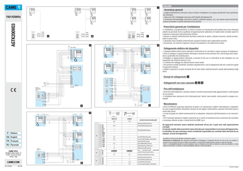
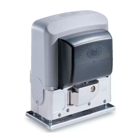
CAME 801XC-0180 User manual

801XC-0180
FA01794M4A
IT Italiano
EN English
FR Français
RU Pусский

Pag. 2- Manuale - FA01794M4A - 04/2022 - © CAME S.p.A. -
9 V
W V U
M N Rc Rc Ra Ra + E -
Ra Rc
ON
OFF

Pag. 3- Manuale - FA01794M4A - 04/2022 - © CAME S.p.A. -
9 V
A

Pag. 4- Manuale - FA01794M4A - 04/2022 - © CAME S.p.A. -
ATS 24V
B

Pag. 5- Manuale - FA01794M4A - 04/2022 - © CAME S.p.A. -
ATS 24V
C

Pag. 6- Manuale - FA01794M4A - 04/2022 - © CAME S.p.A. -
W V U
Ra Rc
ON
OFF
ATS 24V
D

Pag. 7- Manuale - FA01794M4A - 04/2022 - © CAME S.p.A. -
W V U
ON
OFF
Ra
W V U
ON
OFF
Ra Rc
STOP
ATS 24V
E

Pag. 8- Manuale - FA01794M4A - 04/2022 - © CAME S.p.A. -
W V U
ON
OFF
Ra Rc
W V U
ON
OFF
Ra Rc
ATS 24V
STOP
F

Pag. 9- Manuale - FA01794M4A - 04/2022 - © CAME S.p.A. -
ATS 24V
G

Pag. 10 - Manuale - FA01794M4A - 04/2022 - © CAME S.p.A. -
ATS 230V
H

Pag. 11 - Manuale - FA01794M4A - 04/2022 - © CAME S.p.A. -
ATS 230V
W V U
W V U
W V U
I

Pag. 12 - Manuale - FA01794M4A - 04/2022 - © CAME S.p.A. -
W V U
Ra Rc
ON
OFF
ATS 230V
J

Pag. 13 - Manuale - FA01794M4A - 04/2022 - © CAME S.p.A. -
W V U
Ra Rc
ON
OFF
W V U
Rc
ON
OFF
Ra
STOP
ATS 230V
K

Pag. 14 - Manuale - FA01794M4A - 04/2022 - © CAME S.p.A. -
W V U
Ra Rc
ON
OFF
W V U
ON
OFF
Ra Rc
ATS 230V
STOP
L

Pag. 15 - Manuale - FA01794M4A - 04/2022 - © CAME S.p.A. -
ATS 230V
M

Pag. 16 - Manuale - FA01794M4A - 04/2022 - © CAME S.p.A. -
ITALIANO
Avvertenze Generali
Leggere attentamente le istruzioni prima
di iniziare l’installazione ed eseguire
gli interventi come specificato dal
costruttore. • Il prodotto deve essere
destinato solo all’uso per il quale è stato
espressamente studiato e ogni altro
uso è da considerarsi pericoloso. • Il
produttore non può essere considerato
responsabile per eventuali danni causati
da usi impropri, erronei ed irragionevoli.
• Prima di eseguire i collegamenti
elettrici, togliere l'alimentazione e, se
presenti, scollegare le batterie.
Dismissione e smaltimento
Non disperdere nell’ambiente l’imballaggio
e il dispositivo alla fine del ciclo di vita, ma
smaltirli seguendo le norme vigenti nel paese
di utilizzo del prodotto. I componenti riciclabili
riportano simbolo e sigla del materiale.
I DATI E LE INFORMAZIONI INDICATE IN
QUESTO MANUALE SONO DA RITENERSI
SUSCETTIBILI DI MODIFICA IN QUALSIASI
MOMENTO E SENZA OBBLIGO DI PREAVVISO.
LE MISURE, SE NON DIVERSAMENTE
INDICATO, SONO IN MILLIMETRI.
Descrizione
Dispositivo per la regolazione dei finecorsa
per motoriduttori serie ATS.
Descrizione delle parti
1Dispositivo di regolazione finecorsa
2LED di segnalazione tensione presente
3Morsettiera 3 poli
4LED di segnalazione finecorsa chiude
5LED di segnalazione finecorsa apre
6Connettore per morsettiera a 9 poli
7Interruttore di accensione
8Cavo FROR 3x1 mm2 (*)
9Batteria 9V tipo 6F22 o 6LR61 (*)
(*) Accessorio non fornito.
Inserimento / Sostituzione batteria
APer inserire o sostituire la batteria (non
fornita), rimuovere il guscio superiore
utilizzando un cacciavite.
Collegamento del dispositivo e
regolazione dei punti di finecorsa
Procedura su motoriduttori a 24V
Le operazioni vanno eseguite su
entrambi i motoriduttori.
Sbloccare il motoriduttore.
BAprire manualmente l'anta fino al punto
desiderato.
Togliere le coperture di protezione per
accedere alla morsettiera del motoriduttore
e alle astine di regolazione finecorsa.
CScollegare la morsettiera a 9 poli dal
gruppo scheda motoriduttore e collegarla
al connettore del dispositivo di regolazione
finecorsa.

Pag. 17 - Manuale - FA01794M4A - 04/2022 - © CAME S.p.A. -
DPosizionare l’interruttore del dispositivo
in ON.
ERuotare in SENSO ORARIO l’astina
(A) per determinare il punto di finecorsa
in apertura, fino a quando il dispositivo
emetterà un segnale acustico e il LED verde
(Ra) di finecorsa apre si accende.
FChiudere manualmente l'anta.
Ruotare in SENSO ANTIORARIO l’astina
(C) per determinare il punto di finecorsa
in chiusura, fino a quando il dispositivo
emetterà un segnale acustico e il LED rosso
(Rc) di finecorsa chiude si accende.
GAl termine della regolazione, spegnere il
dispositivo (OFF), scollegare la morsettiera a
9 poli dal dispositivo e ricollegarla al gruppo
scheda motoriduttore.
Fissare le coperture di protezione.
Procedura su motoriduttori a 230V
Le operazioni vanno eseguite su
entrambi i motoriduttori.
Sbloccare il motoriduttore.
HAprire manualmente l'anta fino al punto
desiderato.
Togliere le coperture di protezione per
accedere alla morsettiera del motoriduttore
e alle astine di regolazione finecorsa.
ICollegare la morsettiera (W-V-U) del
motoriduttore al dispositivo di regolazione
del finecorsa utilizzando la morsettiera a 3
poli e un cavo FROR 3x1 mm2 (non fornito).
Prima di collegare il motoriduttore al
dispositivo di regolazione, scollegarlo
dal quadro comando o togliere
l’alimentazione di rete!
JPosizionare l’interruttore del dispositivo
in ON.
KRuotare in SENSO ORARIO l’astina
(A) per determinare il punto di finecorsa
in apertura, fino a quando il dispositivo
emetterà un segnale acustico e il LED verde
(Ra) di finecorsa apre si accende.
LChiudere manualmente l'anta.
Ruotare in SENSO ANTIORARIO l’astina
(C) per determinare il punto di finecorsa
in chiusura, fino a quando il dispositivo
emetterà un segnale acustico e il LED rosso
(Rc) di finecorsa chiude si accende.
MAl termine della regolazione, spegnere il
dispositivo (OFF) e scollegare la morsettiera
del motoriduttore dal dispositivo.
Fissare le coperture di protezione.
In caso di impianto con apertura
verso l’esterno, le uniche operazioni
diverse tra quelle indicate sono i punti
E,F, K e L. Per determinare il punto di
finecorsa in apertura, ruotare in SENSO
ANTIORARIO l’astina (C) fino a quando il
LED rosso (Rc) si accende, mentre per il
punto di finecorsa in chiusura, ruotare in
SENSO ORARIO l’astina (A) fino a quando
il LED verde (Ra) si accende.
I contenuti del manuale sono da ritenersi
suscettibili di modifica in qualsiasi momento
senza obbligo di preavviso.

Pag. 18 - Manuale - FA01794M4A - 04/2022 - © CAME S.p.A. -
ENGLISH
General precautions
Read the instructions carefully before
beginning the installation and carry
out the procedures as specified by the
manufacturer. • Only use this product
for its intended purpose. Any other
use is hazardous. • The manufacturer
cannot be held liable for any damage
caused by improper, unreasonable or
erroneous use. • Before connecting
up the electrics, disconnect the power
supply and any batteries.
Dismantling and disposal
Dispose of the packaging and the device
responsibly at the end of its life cycle, in
compliance with the laws in force in the
country where the product is used. The
recyclable components are marked with the
material symbol and ID.
THE DATA AND INFORMATION IN THIS
MANUAL MAY BE CHANGED AT ANY TIME
AND WITHOUT NOTICE.
MEASUREMENTS ARE IN MILLIMETRES,
UNLESS STATED OTHERWISE.
Description
Limit-switch adjustment device for ATS
gearmotors.
Description of parts
1Limit-switch adjustment device
2Power LED
33-pole terminal block
4LED warning light: limit-switch closing
5LED warning light: limit-switch opening
69-pole terminal block connector
7Power switch
8FROR cable 3x1 mm2 (*)
9Battery 9 V type 6F22 or 6LR61 (*)
(*) Accessory not supplied.
Inserting/replacing the battery
ATo insert or replace the battery (not
supplied), remove the upper casing using
a screwdriver.
Connecting the device and
adjusting the limit-switch points
Procedure for 24V gearmotors
Perform these operations on both
gearmotors.
Release the gearmotor.
BManually open the leaf to the desired
point.
Remove the protective covers to access
the gearmotor terminal block and the limit-
switch adjustment rods.
CDisconnect the 9-pole terminal block
from the gearmotor board assembly and
connect it to the limit-switch adjustment
device connector.

Pag. 19 - Manuale - FA01794M4A - 04/2022 - © CAME S.p.A. -
DSet the device switch to ON.
ETurn the rod (A) CLOCKWISE to set the
limit-switch opening point. The device will
beep and the green limit-switch opening
LED (Ra) will switch on.
FClose the gate manually.
Turn the rod (C) ANTICLOCKWISE to set the
limit-switch closing point. The device will
beep and the red limit-switch closing LED
(Rc) will switch on.
GOnce the adjustments have been
made, turn the device OFF. Disconnect
the 9-pole terminal block from the device
and reconnect it to the gearmotor board
assembly.
Attach the protective covers.
Procedure for 230V gearmotors
Perform these operations on both
gearmotors.
Release the gearmotor.
HManually open the leaf to the desired
point.
Remove the protective covers to access
the gearmotor terminal block and the limit-
switch adjustment rods.
IConnect the gearmotor terminal block
(W-V-U) to the limit-switch adjustment
device using the 3-pole terminal block and
a FROR cable 3x1 mm2 (not supplied).
Before connecting the gearmotor
to the adjustment device, disconnect it
from the control panel or disconnect the
power supply.
JSet the device switch to ON.
KTurn the rod (A) CLOCKWISE to set the
limit-switch opening point. The device will
beep and the green limit-switch opening
LED (Ra) will switch on.
LClose the gate manually.
Turn the rod (C) ANTICLOCKWISE to set the
limit-switch closing point. The device will
beep and the red limit-switch closing LED
(Rc) will switch on.
MOnce the adjustments have been made,
turn the device OFF and disconnect the
gearmotor terminal block from the device.
Attach the protective covers.
For outward-opening systems,
points E, F, K and L above are dierent.
To determine the limit-switch opening
point, turn the rod (C) ANTICLOCKWISE.
The red LED (Rc) will switch on. To
determine the limit-switch closing point,
turn the rod (A) CLOCKWISE. The green
LED (Ra) will switch on.
The contents of this manual may be
changed at any time and without notice.

Pag. 20 - Manuale - FA01794M4A - 04/2022 - © CAME S.p.A. -
FRANÇAIS
Instructions générales
Lire attentivement les instructions
avant de commencer l'installation et
d'eectuer les interventions comme
indiqué par le fabricant. • Ce produit ne
devra être destiné qu'à l'utilisation pour
laquelle il a été expressément conçu et
toute autre utilisation est à considérer
comme dangereuse. • Le fabricant
décline toute responsabilité en cas
d’éventuels dommages provoqués par
des utilisations impropres, incorrectes et
déraisonnables. • Avant d'eectuer les
branchements électriques, mettre hors
tension et déconnecter les éventuelles
batteries.
Mise au rebut et élimination
Ne pas jeter l'emballage et le dispositif dans
la nature au terme du cycle de vie de ce
dernier, mais les éliminer selon les normes en
vigueur dans le pays où le produit est utilisé.
Le symbole et le sigle du matériau figurent
sur les composants recyclables.
LE CONTENU DE CE MANUEL EST
SUSCEPTIBLE DE SUBIR DES MODIFICATIONS
À TOUT MOMENT ET SANS AUCUN PRÉAVIS.
LES DIMENSIONS SONT EXPRIMÉES
EN MILLIMÈTRES, SAUF INDICATION
CONTRAIRE.
Description
Dispositif permettant le réglage des butées de
fin de course pour motoréducteurs série ATS.
Description des parties
1
Dispositif de réglage des butées de fin
de course
2
Voyant de signalisation led de présence
de tension
3
Bornier 3 pôles
4
Voyant LED de signalisation fin de course
fermeture
5
Voyant LED de signalisation fin de course
ouverture
6
Connecteur pour bornier à 9 pôles
7
Interrupteur d'allumage
8
Câble FROR 3x1 mm2 (*)
9
Batterie 9V type 6F22 ou 6LR61 (*)
(*) Accessoire non fourni.
Insertion / Remplacement de la pile
A
Pour insérer ou remplacer la pile (non
fournie), enlever le couvercle supérieur à
l'aide d'un tournevis.
Connexion du dispositif et réglage
des points de fin de course
Procédure sur motoréducteurs 24 V
Les opérations doivent être eectuées
sur les deux motoréducteurs.
Débloquer le motoréducteur.
B
Ouvrir manuellement le vantail jusqu'à la
position souhaitée.
Retirer les dispositifs de protection pour
accéder au bornier du motoréducteur et aux
tiges de réglage de la butée de fin de course.
C
Déconnecter le bornier à 9 pôles du
groupe carte motoréducteur et le connecter
au connecteur du dispositif de réglage de la
butée de fin de course.
This manual suits for next models
1
Table of contents
Other CAME Gate Opener manuals
Popular Gate Opener manuals by other brands

DoorKing
DoorKing 9000 Series Installation & owner's manual

BFT
BFT ICARO SMART AC A2000 Installation and user manual

Dea
Dea Ghost 100 Series Operating instructions and warnings

cedamatic
cedamatic GLISS 1000 I Operating instructions and spare parts catalogue

tau
tau speed 2 Use and maintenance manual

Dieffematic
Dieffematic Wheeler Series Installation and use manual