manuals.online logo
Brands
  1. Home
  2. •
  3. Brands
  4. •
  5. Ghost Controls
  6. •
  7. Gate Opener
  8. •
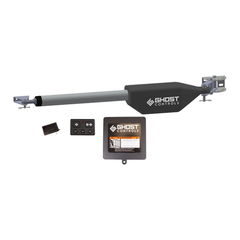
  9. Ghost Controls DTP1 User manual

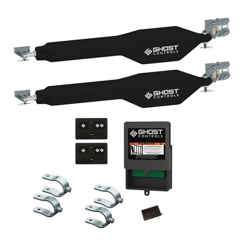
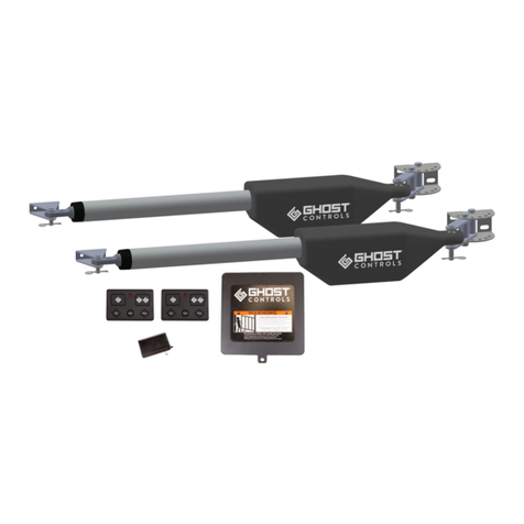
Ghost Controls DTP1 User manual

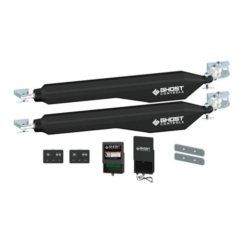
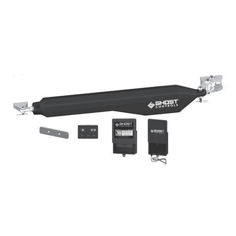
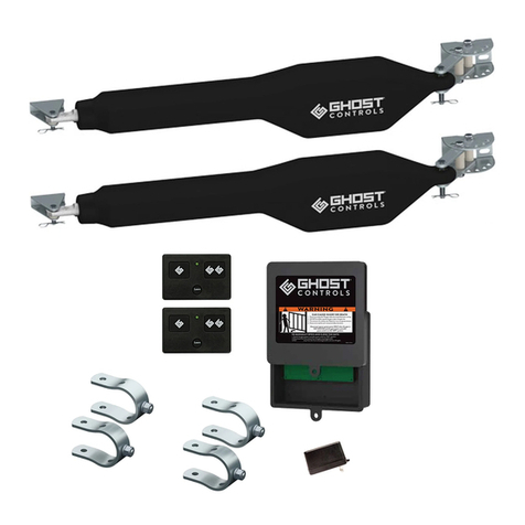
Quickstart Guide for DS1U & DTP1 Single and DD2U & DEP2 Dual Automatic Gate Opener Kits
This installation overview shows the most common installation
of a single, pull to open application and is intended for use as
a guide once you have read and understand the complete
installation manual. Please refer to the installation manual for
safety information prior to installing your automatic gate opener.
The installation manual is required for information on additional
features, programming, dual applications, and push to open
applications.
A complete installation video can be viewed at:
ghostcontrols.com/support/installation-video
3. Align the center of the post pivot bracket over your
established center line and clamp the bracket to the hinge
post.
A
C
D
E
F
G
H
A
C
G
H
F
D
E
SHEET SCALE
DRAWING SHEET TITLE
DRAWN ON
A
PART
DWG
UNLESS OTHERWISE SPECIFIED:
7. Determine the mounting location for the control box
making sure the arm power cable will reach. Pre-drill the
control box mounting holes with a 7/32" drill bit and mount
using the screws provided with the control box.
A
C
D
E
F
G
H
A
C
G
H
F
D
E
SHEET SCALE
DRAWING SHEET TITLE
DRAWN ON
A
PART
DWG
UNLESS OTHERWISE SPECIFIED:
PREPARE THE GATE
Post must be a minimum of 6"x 6" wood or 3" steel
and set in concrete. Gate must be plumb, level, and
swing freely. Wheels cannot be used and ball bear-
ing hinges are recommended for gates weighing over
200 lbs. Operator is not for use on solid panel gates.
A
C
D
E
F
G
H
A
C
G
H
F
D
E
SHEET SCALE
DRAWING SHEET TITLE
DRAWN ON
A
PART
DWG
UNLESS OTHERWISE SPECIFIED:
4. Adjust the post bracket and pivot brackets as needed
to achieve a minimum of 4" clearance between the hole in
the pivot brackets and the inside of the gate in the desired
open position. Add the 2nd pivot bracket bolt and tighten
both.
>4.0
A
C
D
E
F
G
H
A
C
G
H
F
D
E
SHEET SCALE
DRAWING SHEET TITLE
DRAWN ON
A
PART
DWG
UNLESS OTHERWISE SPECIFIED:
8. Insert the battery harness through the strain relief and
attach to the control board, then attach the other end to
your battery. ABBT Battery Box Kit not shown here.
A
C
D
E
F
G
H
A
C
G
H
F
D
E
SHEET SCALE
DRAWING SHEET TITLE
DRAWN ON
A
PART
DWG
UNLESS OTHERWISE SPECIFIED:
1. Operator should be mounted as close to the center of
the gate as possible. Determine the mounting location of
the operator and mark the center line on the gate hinge
post.
A
C
D
E
F
G
H
A
C
G
H
F
D
E
SHEET SCALE
DRAWING SHEET TITLE
DRAWN ON
A
PART
DWG
UNLESS OTHERWISE SPECIFIED:
5. Mark the bolt holes and drill using a 7/16" drill bit.
Install the 4 mounting bolts and tighten.
A
C
D
E
F
G
H
A
C
G
H
F
D
E
SHEET SCALE
DRAWING SHEET TITLE
DRAWN ON
A
PART
DWG
UNLESS OTHERWISE SPECIFIED:
9. Insert the arm cable through the strain relief and attach
using the screw terminals on the control board. Make the
screw terminal connections are tight and are contacting
the wire and not the wire insulation. Tighten strain relief.
A
C
D
E
F
G
H
A
C
G
H
F
D
E
SHEET SCALE
DRAWING SHEET TITLE
DRAWN ON
A
PART
DWG
UNLESS OTHERWISE SPECIFIED:
2. Pre-assemble the post pivot bracket as shown. Do not
completely tighten at this point..
Assembled
Exploded
6
5
4
3
1
A
C
D
E
F
G
H
B
6
2
3
1
5
4
A
C
G
H
F
B
D
E
SHEET SIZE
SHEET SCALE
PART/ASSEMBLY NUMBER
PART/ASSEMBLY DESCRIPTION
DRAWING SHEET TITLE
DWG REVISOR
DRAWN BY
DRAWN ON
REVISED ON
2018May17
Sheet1
A
2018Apr13
1:2
CAY
CAY
2
PART
DWG
1
PART/ASSEMBLY CONFIGURATION NAME
MATERIAL(S)
THE INFORMATION CONTAINED IN THIS DRAWING IS THE SOLE
PROPERTY OF GHOST CONTROLS, LLC. ANY REPRODUCTION IN
PART OR AS A WHOLE WITHOUT THE WRITTEN PERMISSION OF
GHOST CONTROLS, LLC. IS PROHIBITED. DESIGNS, PRODUCTS,
AND DRAWINGS ARE SUBJECT TO CHANGE WITHOUT NOTICE.
1 of 1
REVISION
NUMBERS
UNLESS OTHERWISE SPECIFIED:
LENGTH DIMENSIONS PROVIDED ARE IN MILLIMETERS (mm)
LENGTH DUAL DIMENSIONS ARE IN INCHES (in)
ANGULAR DIMENSIONS PROVIDED ARE IN DEGREES (
)
QS030 Pre-assembly
PAGE NUMBER
QS030 Bracket Pre-assembly
DRAWING FILE NAME
PART/ASSEMBLY FILE NAME
PBR6AA Post Mount Bracket Assem
6. Install the rear of the operator using the clevis pin,
bushing, and hairclip as shown.
A
C
D
E
F
G
H
A
C
G
H
F
D
E
SHEET SCALE
DRAWING SHEET TITLE
DRAWN ON
A
PART
DWG
UNLESS OTHERWISE SPECIFIED:
10. Verify that the dip switches are set to the correct
position as shown.
DIP # OFF Position ON Position
1Factory Default:
Pull-To-Open Push-To-Open
2Warning Disabled Factory Default:
Warning Enabled
3Factory Default:
SafeForce®Mode
Monitored
External Safety
Devices Mode
4
Factory Default:
Delay Open 2nd
Arm
Simultaneous
Open
11. Turn the control box to the on position using the switch
located on the bottom left side of the control box. Press
and hold the Transmitter Button to run the arm out a few
inches. Press the Transmitter button to retract the arm
until it stops on its own. Turn the control box o.
6
5
4
3
1
A
C
D
E
F
G
H
B
6
2
3
1
5
4
A
C
G
H
F
B
D
E
SHEET SCALE
PART/ASSEMBLY NUMBER
PART/ASSEMBLY DESCRIPTION
DRAWING SHEET TITLE
DWG REVISOR
DRAWN BY
DRAWN ON
REVISED ON
2018May18
Actuator Extension
A
2018May18
1:60
2
PART
DWG
00
PART/ASSEMBLY CONFIGURATION NAME
MATERIAL(S)
THE INFORMATION CONTAINED IN THIS DRAWING IS THE SOLE
PROPERTY OF GHOST CONTROLS, LLC. ANY REPRODUCTION IN
PART OR AS A WHOLE WITHOUT THE WRITTEN PERMISSION OF
GHOST CONTROLS, LLC. IS PROHIBITED. DESIGNS, PRODUCTS,
AND DRAWINGS ARE SUBJECT TO CHANGE WITHOUT NOTICE.
1 of 1
REVISION
NUMBERS
UNLESS OTHERWISE SPECIFIED:
LENGTH DIMENSIONS PROVIDED ARE IN MILLIMETERS (mm)
LENGTH DUAL DIMENSIONS ARE IN INCHES (in)
ANGULAR DIMENSIONS PROVIDED ARE IN DEGREES (
)
QSD120 Extend Arm
PAGE NUMBER
QSD120 Extend Arm
DRAWING FILE NAME
PART/ASSEMBLY FILE NAME
Quick Start D-series Assembly
SHEET SIZE
14B. Place the bracket assembly on the gate and tighten
the bolts. This will determine the open position of the gate.
Adjust the gate bracket as needed to achieve the desired
open position.
A
C
D
E
F
G
H
A
C
G
H
F
D
E
SHEET SCALE
DRAWING SHEET TITLE
DRAWN ON
A
PART
DWG
UNLESS OTHERWISE SPECIFIED:
18.Press and hold the 1st SET button until it beeps,
then release. Press the transmitter button to activate
the gate and let the gate open fully. When the gate
reaches its open position, the control board will sound
a single beep, confirming the closed limit has been set.
12. The arm has an internal limit switch that is fixed and is
not adjustable. The arm in the fully retracted position will
determine the open position of the gate.
6
5
4
3
1
A
C
D
E
F
G
H
B
6
2
3
1
5
4
A
C
G
H
F
B
D
E
SHEET SCALE
PART/ASSEMBLY NUMBER
PART/ASSEMBLY DESCRIPTION
DRAWING SHEET TITLE
DWG REVISOR
DRAWN BY
DRAWN ON
REVISED ON
2018May18
Actuator Retraction
A
2018May18
1:60
2
PART
DWG
00
PART/ASSEMBLY CONFIGURATION NAME
MATERIAL(S)
THE INFORMATION CONTAINED IN THIS DRAWING IS THE SOLE
PROPERTY OF GHOST CONTROLS, LLC. ANY REPRODUCTION IN
PART OR AS A WHOLE WITHOUT THE WRITTEN PERMISSION OF
GHOST CONTROLS, LLC. IS PROHIBITED. DESIGNS, PRODUCTS,
AND DRAWINGS ARE SUBJECT TO CHANGE WITHOUT NOTICE.
1 of 1
REVISION
NUMBERS
UNLESS OTHERWISE SPECIFIED:
LENGTH DIMENSIONS PROVIDED ARE IN MILLIMETERS (mm)
LENGTH DUAL DIMENSIONS ARE IN INCHES (in)
ANGULAR DIMENSIONS PROVIDED ARE IN DEGREES (
)
QSD130 Retract Arm
PAGE NUMBER
QSD130 Retract Arm
DRAWING FILE NAME
PART/ASSEMBLY FILE NAME
Quick Start D-series Assembly
SHEET SIZE
15. If using AC power to recharge your battery, connect
the transformer wires to the transformer and to the
control board as shown. The transformer is not polarity
sensitive so either wire can go to either terminal. The two
left terminals (solar) will not be used. Do not plug in the
transformer until the wiring has been completed.
6
5
4
3
1
A
C
D
E
F
G
H
B
6
2
3
1
5
4
A
C
G
H
F
B
D
E
SHEET SCALE
PART/ASSEMBLY NUMBER
PART/ASSEMBLY DESCRIPTION
DRAWING SHEET TITLE
DWG REVISOR
DRAWN BY
DRAWN ON
REVISED ON
2018May17
18VAC Power Wiring
A
2018May08
1:2
2
PART
DWG
0
PART/ASSEMBLY CONFIGURATION NAME
MATERIAL(S)
THE INFORMATION CONTAINED IN THIS DRAWING IS THE SOLE
PROPERTY OF GHOST CONTROLS, LLC. ANY REPRODUCTION IN
PART OR AS A WHOLE WITHOUT THE WRITTEN PERMISSION OF
GHOST CONTROLS, LLC. IS PROHIBITED. DESIGNS, PRODUCTS,
AND DRAWINGS ARE SUBJECT TO CHANGE WITHOUT NOTICE.
1 of 1
REVISION
NUMBERS
UNLESS OTHERWISE SPECIFIED:
LENGTH DIMENSIONS PROVIDED ARE IN MILLIMETERS (mm)
LENGTH DUAL DIMENSIONS ARE IN INCHES (in)
ANGULAR DIMENSIONS PROVIDED ARE IN DEGREES (
)
QS170 18VAC Wiring
PAGE NUMBER
QS170 18VAC Power Wiring
DRAWING FILE NAME
PART/ASSEMBLY FILE NAME
cbox-asm_asm
SHEET SIZE
19. Press the transmitter button to activate the gate and
confirm the closed position has been set correctly. Repeat
steps 19 and 20 if needed to change your desired closed
position.
13. Please refer to the installation manual for instructions
on assembly and mounting options for the front mount to
tubular gates or to decorative gates.
16. If solar power is being used to charge your battery,
connect the red wire from the solar panel to the positive
(+) terminal and connect the black wire to the negative (-)
terminal as shown. The two right terminals (AC) will not be
used. Do not use solar and transformer power at the same
time.
6
5
4
3
1
A
C
D
E
F
G
H
B
6
2
3
1
5
4
A
C
G
H
F
B
D
E
SHEET SCALE
PART/ASSEMBLY NUMBER
PART/ASSEMBLY DESCRIPTION
DRAWING SHEET TITLE
DWG REVISOR
DRAWN BY
DRAWN ON
REVISED ON
2018May17
Solar Power Wiring
A
2018May08
1:2
2
PART
DWG
0
PART/ASSEMBLY CONFIGURATION NAME
MATERIAL(S)
THE INFORMATION CONTAINED IN THIS DRAWING IS THE SOLE
PROPERTY OF GHOST CONTROLS, LLC. ANY REPRODUCTION IN
PART OR AS A WHOLE WITHOUT THE WRITTEN PERMISSION OF
GHOST CONTROLS, LLC. IS PROHIBITED. DESIGNS, PRODUCTS,
AND DRAWINGS ARE SUBJECT TO CHANGE WITHOUT NOTICE.
1 of 1
REVISION
NUMBERS
UNLESS OTHERWISE SPECIFIED:
LENGTH DIMENSIONS PROVIDED ARE IN MILLIMETERS (mm)
LENGTH DUAL DIMENSIONS ARE IN INCHES (in)
ANGULAR DIMENSIONS PROVIDED ARE IN DEGREES (
)
QS180 Solar Power
PAGE NUMBER
QS180 Solar Power Wiring
DRAWING FILE NAME
PART/ASSEMBLY FILE NAME
cbox-asm_asm
SHEET SIZE
20. For a Dual system, repeat steps 3-7, 10, 12-16, and
19-21 with the second operator arm. We recommend that
you get the first arm completely installed and working
properly before installing the second arm so that you can
isolate any connection problems on each arm before
proceeding further.
14A. Move the gate to the desired open position. Attach
the gate bracket assembly to the fully retracted operator
as shown.
A
C
D
E
F
G
H
A
C
G
H
F
D
E
SHEET SCALE
DRAWING SHEET TITLE
DRAWN ON
A
PART
DWG
UNLESS OTHERWISE SPECIFIED:
17. Turn the control box on. Press and hold the JOG
CLOSE button until the gate reaches your desired closed
position. Use both JOG OPEN and JOG CLOSE as
needed to fine tune your desired closed position.
21. To set the autoclose feature, press and hold the “SET
AUTOCLOSE TIME” button until it beeps. Wait until the
desired auto close time has been reached (the led will blink
once a second) then press and release the “set auto close
time” button. Autoclose time can be set from 6 seconds to
60 minutes.
CLOSE-UP VIEW
OF BOTTOM OF
CONTROL BOX
QSG6BA-0818

Other manuals for DTP1

1

This manual suits for next models

3

Other Ghost Controls Gate Opener manuals

Ghost Controls DTP1 Installation instructions

Ghost Controls

Ghost Controls DTP1 Installation instructions

Ghost Controls HDP1 Installation instructions

Ghost Controls

Ghost Controls HDP1 Installation instructions

Ghost Controls TDS2 Installation instructions

Ghost Controls

Ghost Controls TDS2 Installation instructions

Ghost Controls Ghost Pro Series Installation instructions

Ghost Controls

Ghost Controls Ghost Pro Series Installation instructions

Ghost Controls DEP2 Installation instructions

Ghost Controls

Ghost Controls DEP2 Installation instructions

Ghost Controls DTP1XP Installation instructions

Ghost Controls

Ghost Controls DTP1XP Installation instructions

Ghost Controls TSS1 User manual

Ghost Controls

Ghost Controls TSS1 User manual

Ghost Controls HDP2 Installation instructions

Ghost Controls

Ghost Controls HDP2 Installation instructions

Ghost Controls ZombieLock User manual

Ghost Controls

Ghost Controls ZombieLock User manual

Ghost Controls HDP1 Installation instructions

Ghost Controls

Ghost Controls HDP1 Installation instructions

Ghost Controls TSS1 Installation instructions

Ghost Controls

Ghost Controls TSS1 Installation instructions

Ghost Controls Ghost Pro LSM1 Installation instructions

Ghost Controls

Ghost Controls Ghost Pro LSM1 Installation instructions

Popular Gate Opener manuals by other brands

CAME BK Series installation manual

CAME

CAME BK Series installation manual

Chamberlain MotorLift HC280ML Mechanical installation

Chamberlain

Chamberlain MotorLift HC280ML Mechanical installation

Allmatic PLUS instructions

Allmatic

Allmatic PLUS instructions

FAAC Estate Swing E-S 1100 Series instruction manual

FAAC

FAAC Estate Swing E-S 1100 Series instruction manual

CAME FROGPLUS-S7 Quick setup guide

CAME

CAME FROGPLUS-S7 Quick setup guide

OSCO LA36 installation guide

OSCO

OSCO LA36 installation guide

PowerTech PW330L user manual

PowerTech

PowerTech PW330L user manual

OSCO MSG-A installation guide

OSCO

OSCO MSG-A installation guide

Guardian 415 owner's manual

Guardian

Guardian 415 owner's manual

Nice MhouseKit SL1W Instructions and warnings for installation and use

Nice

Nice MhouseKit SL1W Instructions and warnings for installation and use

RIB MAGIC 105 manual

RIB

RIB MAGIC 105 manual

Nice TTN3724HS Instructions and warnings for installation and use

Nice

Nice TTN3724HS Instructions and warnings for installation and use

Merlin G815D Instructions for installation & use

Merlin

Merlin G815D Instructions for installation & use

Platinum Access Systems BLSL2250 Installation instructions & owner's manual

Platinum Access Systems

Platinum Access Systems BLSL2250 Installation instructions & owner's manual

Stagnoli ULIXES manual

Stagnoli

Stagnoli ULIXES manual

Mighty Mule FM500 installation manual

Mighty Mule

Mighty Mule FM500 installation manual

Portamatik ROSSO 60 User's and installer's manual

Portamatik

Portamatik ROSSO 60 User's and installer's manual

FAAC 740 manual

FAAC

FAAC 740 manual

manuals.online logo
manuals.online logoBrands
  • About & Mission
  • Contact us
  • Privacy Policy
  • Terms and Conditions

Copyright 2025 Manuals.Online. All Rights Reserved.