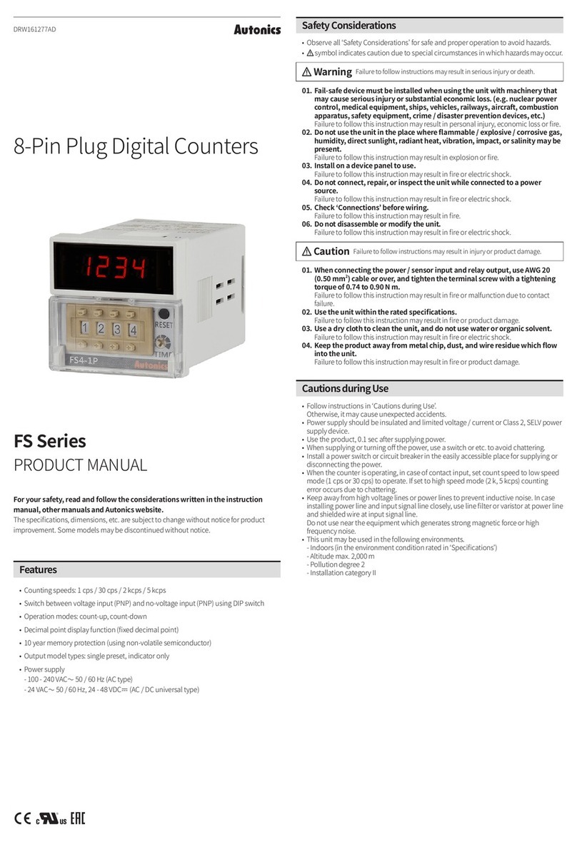
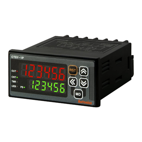
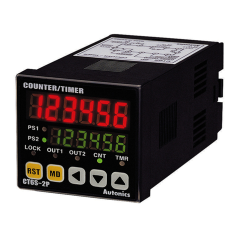
Autonics CT Series User manual

1.
CT
CT Series Timer/Counter Multi-function
24 Power Supply is also available as special order. Please indicate your requirement in your order
*
Page 01 KKCTE02T-A/0-20131221
CT Series Multi
-function Counter/Timer
For your safety, please read the below content carefully before you use the meter !
Safe Caution
Please comply with the below important points:
Warning An accident may happen if the operation does not comply with the instruction.
Notice An operation that does not comply with the instruction may lead to product damage.
The instruction of the symbol in the manual is as below:
An accident danger may happen in a special condition.
Warning
1. A safety protection equipment must be installed or please contact with us for the relative information if the product is used under
the circumstance such as nuclear control, medical treatment equipment ,automobile, train, airplane, aviation, entertainment or safety
equipment, etc. Otherwise, it may cause serious loss, fire or person injury.
2. Apanel must be installed, otherwise it may cause creepage (leakage).
3. Do not touch wire connectors when the power is on, otherwise you may get an electric shock.
4. Do not dismantle or modify the product, If you have to do so, please contact with us first. Otherwise it may cause electric shock
and fire.
5. Please check the connection number while you connect the power supply wire or input signal, otherwise it may cause fire.
.
Caution
1. This product cannot be used outdoors. Otherwise the working life of the product will become shorter, or an electric shock accident
may happen.
2. When you connect wire to the power input connector or signal input connectors, the moment of the No.20AWG (0.50 mm2) scrwew
tweaked to the connector is 0.74n.m-0.9n.m. Otherwise the connectors may be damaged or get fire.
3. Please comply with the rated specifications. Otherwise it may cause fire after the working life of the product becomes shorter.
4. Do not use water or oil base cleaner to clean the product. Otherwise it may cause electric shock or fire, and damage the product.
5. This product should be avoid working under the circumstance that is flammable, explosive, moist, under sunshine, heat radiation and
vibration.
6. In this unit it must not have dust or deposit, otherwise it may cause fire or mechanical malfunction.
7. Do not use gasoline, chemical solvent to clean the cover of the product because such solvent can damage it. Please use some soft
cloth with water or alcohol to clean the plastic cover.
For your safe, please read the below content carefully before you use the timer/counter!
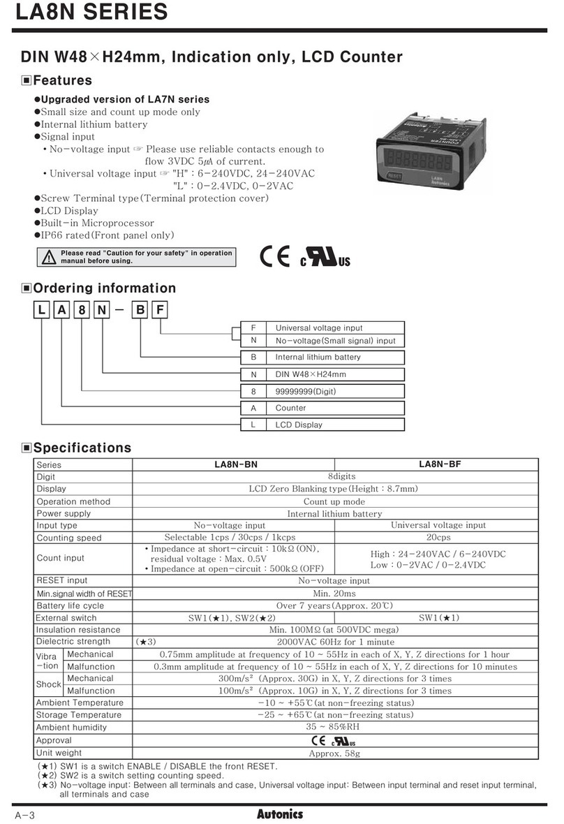
1.Maximum counting speed is 10Kcps.
2. Coefficent can be set as 0.001-99.999
3. Pulse input , PNP and NPN input can be set in the menu
4. With timing function , 9 kinds timing mode can be selected
5. Two loop alarms output for counting length/quantity , one
alarm for batch counting
6. Can be applied to the measure and control in light industry,
machinery , packing and food industry.
Features:
Model Illustration
6
Display: 6: 6 digit display
S: 48H*48Wmm M:72H*72Wmm Y:36H*72Wmm
2 P
2P: 2 loop preset , 1P: 1 loop preset
4
Design code
Page 02 KKCTE02T-A/0-20131221
3.Panel Indication
Reset
Batch setting key
Function key Parameter modifying key
PS1: Indicate that setting value of OUT1
BA.S:Above LED display batch counting value
Lock: (CT16,CT8 without indicate light)
OUT1,OUT2: OUT1 or OUT2 output indicate
BA.0 :Batch output indicate(CT3,CT4 without indicate light)
CNT: Counting mode
TMR:Timing mode
PS1
PS2
BA.S
LOCK OUT1 OUT2 BA.0 CNT TMR
RST BA MD
being displayed on the below LED
PS2: Indicate that setting value of OUT2
being displayed on the below LED
Below LED display batch setting value
Key lock indication
2. Technical Specification
-10~ +50
Selectable voltage input or Non-voltage input
Voltage input : Input impedance:5.4k , H level :5 -30VDC, L level: 0-2VDC, L level: Max.2VDC,
Non-voltage input :Short-circuit impedance:Max.1k,Residual voltage:Max.2VDC,
OPen-circuit impedance:Min.100k
Power Supply
Allowable Voltage Range 90~110% of rated voltage(AC power)
Reset input: Selectable 1ms or 20ms
Min.input
Signal width
Counter
Timer
Input
One-shot output 10/50/100/200/500/1000/2000/5000ms
Control
Output
Contact Point
Capacity NO:250VAC 3A at resistive load, NC:250VAC 2A at resistive load
Solid State Relay
Capacity
~
+65
~
INA, INHIBIT, RESET, BATCH RESET: Selectable 1ms or 20ms
100-240V AC/DC
INA INB input frequency 1Hz, 30Hz, 1KHz , 5KHz ,10KHz are selectable
℃(at non-freezing status)
Timing Accuracy Power on start accuracy: 0.05%
Signal start accuracy :
0.05sec
0.05% 0.03sec
External sensor power 12V DC 10%, Maximum 100mA
Memory time memory datasheet for 10 years
Insulation resistance Min 100M ( at 500V DC)
Dielectric Strength 2000V AC 50/60Hz 1minute
Anti-interfere 2kV , the square wave generator interference ( pulse width: 1uS)
Max. 30VDC , Max. 100mA
Vibration
Shock
Relay
life cycle
Mechnical amplitude : 0.75mm , frequency : 10 55Hz, X , Y , Z directions each for 1 hour
amplitude: 0.5mm , frequency:10 55Hz , X , Y , Z directions each for 10 minutes
~
Malfunction
Mechnical
Malfunction
Mechnical
Electrical
more than 10,000,000 times
More than 100,000 times , (NO: 250VAC 3A load , NC: 250V AC 2A load)
300/S2( about: 30G) X , Y , Z directions for 3 times each
100/S2( about: 10G) X , Y , Z directions for 3 times each
Work temperature
Storage temperature
Storage humidity 35 85%RH

Page 03 KKCTE02T-A/0-20131221
5 times
MD
ss to
99.9s)
4.Operation Procedure:
5.1.Change of the setting value of Counter
How to change preset : To change the preset value from 175 to 180.
PS1
PS2
BA.S
LOCK OUT1 OUT2 BA.0 CNT TMR
RST BA MD
PS1
PS2
BA.S
LOCK OUT1 OUT2 BA.0 CNT TMR
RST BA MD
Change by pressing or
Under measuring status , press key to enter the setting value modify status , the selected digit
always flickers from right to left.
PS1
PS2
BA.S
PS1
PS2
BA.S
LOCK OUT1 OUT2 BA.0 CNT TMR
RST BA MD
Under measuring status, press to enter
setting value modify status , press
continuously , select digit to make it flicker
Press key to select data flickering . PS1
PS2
Press once,change to ,then pre
confirm and return to measuring status .
PS1
PS2
BA.S
LOCK OUT1 OUT2 BA.0 CNT TMR
RST BA MD
5.2 Change the setting value of the timer
Running Mode Change preset time
t. OFF MD MD
t. ON
Change delay time
In the status of changing preset value, if no press any key during 60 seconds, the timer will return to Running Mode.
How to change t. OFF time from 30 sec. to 50 sec., t.ON setting from 40 sec. to 20 sec. (Output mode: FLK, Timer range: 0.1s-999
PS1
PS2
BA.S
LOCK OUT1 OUT2 BA.0 CNT TMR
RST BA MD
Press key to enter the
status of changing preset time.
Make the data flicker by
pressing key twice.
PS1
PS2
BA.S
LOCK OUT1 OUT2 BA.0 CNT TMR
RST BA MD
Change to by pressing
key twice.
Pressing key to complete
t.OFF time setting then enter the
status of changing t.ON time.
MD
PS1
PS2
BA.S
LOCK OUT1 OUT2 BA.0 CNT TMR
RST BA MD
Press key twice
to move the flickering PS1
PS2
BA.S
LOCK OUT1 OUT2 BA.0 CNT TMR
RST BA MD
Pressing key to complete
the setting , then return to
RUN mode.
Press key twice to change
MD
(1)
value
(2)
“5” to “0”
(3) (4)
“7”
“7” “8”
1.
2.
(1) (2)
“3”
“3” “5”
In timing status ,press to enter setting value modify status .The of the data
selected flickering from right to left .
sequence
(3)
to digit “4”
(4)
“4” to “2”
“5”
5.Batch Counting and Batch Preset
Batch Output Action
Batch Reset
Batch Preset Value
0
Batch Output
Batch counting
1.
When batch counting value is beyond 999999 , it will reset to zero automatically , and restart to count.
Batch counting value is up counting , it only can be reset by the external batch reset signal .
Batch counting value is not affected by RST key or external reset signal.

Page 04 KKCTE02T-A/0-20131221
6.Lock Key Setting
Lock Key function is used for avoiding key mis-pressing.
L.OFF (LOCK OFF): Cancel Lock Key function.
LOC.1(LOCK LEVEL1): Lock RST Key
LOC.2(LOCK LEVEL2): Lock and and Key.
LOCK.3(LOCK LEVEL3): Lock RST and and and Key.
(1) Batch counting under counting mode
When counting alarm output times reaching to the preset batch value , batch alarm output .
(2) Batch counting under timing mode
When timing alarm output reaches to the preset batch value , batch alarm output .
Under FLK output mode , when the batch counting value is increasing , preset time of Toff and Ton will pass .
Batch output function
If batch output is ON , it will keep status till batch reset signal comes .
If batch output is ON , the meter power off and power on again , batch output should keep ON status till external reset signal comes.
When using batch control output , up counting time interval will be more than 10ms
times
ON
2.
Running mode
BA MD
Batch preset value modify status
For Example:Pulse number is a number of pulse generated by rotary encoder, L is the measured length, Prescale value is
equal to L divides P.
Modify batch preset vaule
.
MD
If batch preset value is set as 0 , batch output is on OFF status .
In batch setting satus , if there is no any operation in 60S , the meter will come back to measure status automatically .
BA
Under running status , press key to enter batch preset value modify status.
The method of modifying batch output preset value is the same as setting counting value , press key to select the data need to be modified and
make it flickering . Press key to modify the value , press to complete the setting and return to measuring status.
When entering batch preset value modifying mode , the above line LED display the present batch counting value.
When batch preset value is beyong batch counting value , change the batch preset value equal to or smaller than the batch counting value , batch
output will make action.
旋转编码器
刀具
滚轮
电机
计数器和旋转编码器控制长度
π×滚轮的直径( D )
系数值 = ------------------------
编码器旋转一周的脉冲个数
电机控制系统
计数器
π×Diameter of the roller( D )
Prescale Value = ---------------------------------
Pulse number per 1 revolution of the encoder
Set 0.069 of prescale value at perscale value ste mode.
3.1416×22
= ------------------
1000
= 0.069mm/pulse
To use counter and rotary to control length
Rotary encoder
Motor
Motor controlling system
Roller
Cutter
Counter
The diameter of the wheel which connects the rotary coder is 22mm,
The pulses number per 1 revolution of encoder is 1000 pcs.

Page 05 KKCTE02T-A/0-20131221
7. Counting function mode setting
Setting mode
Input mode
Maximum
counting speed
Output mode
OUT2 output
time
OUT1 output
time
Input logic
Min.reset time
Decimal point
Prescale value
Memory
retention
Lock key
Counter/Timer
Up or Down inut mode
Up/Down- A, B, C inut mode
Unit: ms
Unit: ms
Use or to select PnP or nPn
Unit: ms
Min. external RESET signal width
: Power reset for counting value.
(Reset counting value when power off)
: Memorize counting value
(Memorize counting value when power off)
: Counter
: Timer
When output mode is S , T ,D , the input mode only can be Ud-A , B , C.
Counting speed means the allowable maximum
inpu frequency of INA and INB . Eg: If set CPS
as 5K , when input frequency signal is larger
than 5K , the counting will be not correct.
( 、▲)
MD
MD
MD
MD
MD
MD
MD
MD
MD
MD
MD
▲
MD
▲
- - - - - - → - - - - - - →- - - - - - → - - - - - -
* * *
Shift the flickering digit
Change the prescale value
Set range of prescale value
6 Digit: 0.001 ~ 99.999
▲
▲
prescale value: It is actual length or other measure unit per one pulse
▲
Selection and setting

Page 06 KKCTE02T-A/0-20131221
If select F or N mode , when counting value reaches the preset value , output will maintain , therefore there is no
menu in function setting mode.
If S,T, D mode , input mode can only choose Ud-A,B, C mode .If input mode choose Up/Down mode , output mode can select
any mode except S , T , D
When select D output mode , if counting frequecy more than 1Kcps , as there is a responding time of the relay , it may cause the output
action abnormal , so please choose SSR output .
When max. counting speed is 5kcps or 10kcps , if change the output mode to mode , counting speed turn to 1k cps automatically .
In function setting mode , external input signal still can be recognized , when exit the function setting mode , display value and output
will reset automatically .
8 .Timing function mode setting
“OUT2 output time”
output is
“D”
MD
MD
MD
MD
MD
MD
MD
MD
→
→
Up Down
→
→
U
.
Setting Mode Selection and Setting
select output delay time
use and to select input mode .

Page 07 KKCTE02T-A/0-20131221
9. Timing Range
10. Input operation mode for counter
INB=L, INA input pulse count up
INB=H , INA forbit counting.
INA: Count input
INB: Control input
INA: Control input
INB: Count input
INA=H, INB input pulse count up
INA=L, INB forbit counting
INA: Count input
INB: Control input
INB=L , INA input pulse count down
INB=H, INA forbit counting

Page 08 KKCTE02T-A/0-20131221
When you use an encoder and connect its phase A and Phase B output to the INA and INB input
of the counter, please set the mode of the counter as Ud-C.
Input type
Code
11.Output operation mode(Counter)

Page 09 KKCTE02T-A/0-20131221
status
status when display
status
status when display
status
Operation mode in Counter
12. Operation Mode Changing
Operation mode in Timer
When using this unit as a counter, you can change its mode to

Page 10 KKCTE02T-A/0-20131221
Output operation mode(Timer)
Hold output

Page 11 KKCTE02T-A/0-20131221

Page 12 KKCTE02T-A/0-20131221
Input connections
13.
+12V
OV
(CT Series)
Counter
+12V
OV
(CT Series)
Counter
Sensor
+12V
INA
GND
INA
GND
1: Input logic:No-voltage input(NPN)
Solid state relay input
Standard s n
e sor: NPN output sensor
To the internal circuit
(NPN No-voltage input)
Contacts connecting input
To the internal circuit
.
.
..
.
.
..
count speed set to 1 or 30cps (counter)
5.4KΩ
5.4KΩ

Page 13 KKCTE02T-A/0-20131221
15. Dimension & Mounting size mm
CT6Y:(36*72)
(48*48)
(72*72)
72
48
72
Model AH(Min)
G
B C D E F
J
36
48
72
85.5
101
100
6
10
10
79.5
91
90
67
45.5
68
25
25
25
31
45.5
68
30.5
45
67.5
K
(Min)
25
25
25
Remark Unit (mm) Tolerance+0.5%(Special indicated model is not included)
A
B
C
E
D
F
G
K
J+0.5
-0
+0.5
-0 H
Panel size Side-face size Mounting size
+12V
OV
+12V
OV
(PNP Voltage input) (CT Series)
+12V
INA
GND
+12V
INA
2: Input logic:voltage input(PNP)
(Solid state relay input )
Standard sensor: PNP output sensor
Sensor Counter
To the internal circuit
Contacts connecting in
Counter
(CT Series)
14.Output Connecting
Relay output
Counter
Load power
Load
SSR output
Counter
load power
(DC)
(+)
(-)
SSR output
1.Adopt proper load and power,output of the SSR can’t be
too large ,capacity (30VDC.100mA)
2.Make sure the power supply not connected inversally
3.When adopt inductive load (such as relay ),
Filter circuit (such as diode,rheostat)should be connected
between the two ends of the load .
Load
16. Connecting Drawing
891
0111213
)
)
**
!
1234567
OUT2 OUT1 POWER
AC/DC
100~240V
INA INB
+12V
100mA OV RESET OUT2
CT6S:
CT6M:
CT6Y CT6S
CT6M
Please refer to the connection drawing on the meter if have any changes.
5.4KΩ
5.4KΩ
Counting speed set to 1 or 30cps (counter)
.
.
..
.
.
..
.
.
..
12345
INA
AC/DC
100~240V
POWER
6789
1 0
1 1
1 2
OUT2
OUT2
OUT1
100mA OV RESET
INB +12VDC
~
OUT2
OUT1
SOLID STATE
1
2
3
4
5
6
7
8
9
1 0
1 1
1 2
1 3
1 4
1 5
1 6
1 7
1 8
BATCH
OUTPUT COMMON
INA
+12VDC
OV
INB
INHIBIT
BATCH
RESET
RESET
100mA
AC/DC
100~240V
POWER
OUT1
OUT2
OUT
~
Other manuals for CT Series
3
This manual suits for next models
3
Table of contents
Other Autonics Cash Counter manuals

Autonics
Autonics FS4A User manual

Autonics
Autonics CT Series User manual

Autonics
Autonics LA8N Series User manual

Autonics
Autonics CTS Series User manual

Autonics
Autonics CT6Y User manual

Autonics
Autonics LA8N Series User manual

Autonics
Autonics FXS Series User manual

Autonics
Autonics LA8N Series User manual

Autonics
Autonics FS Series User manual

Autonics
Autonics CTS Series User manual