8(16)
Make sure that all three couplings are properly connected, otherwise the hydraulic
motors of the attachment may get damaged.
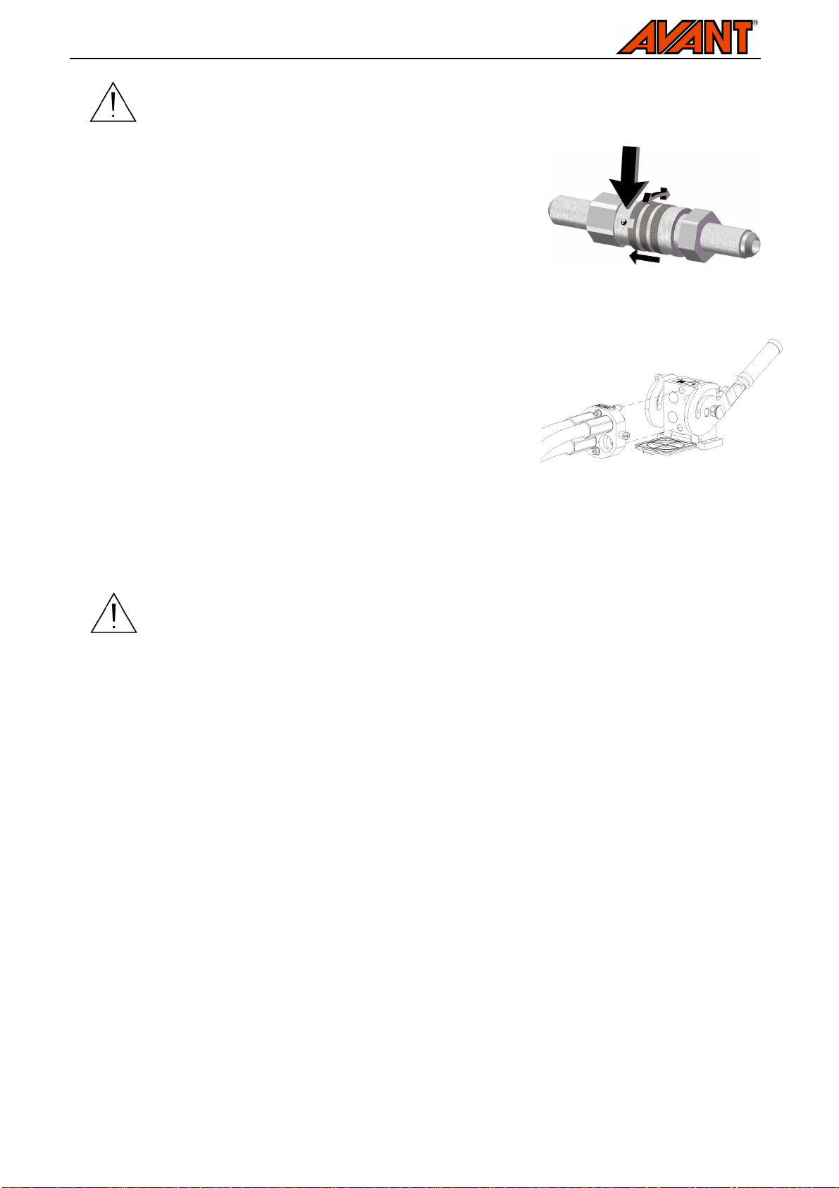
In a 200-series machine, the hose can be connected by pushing the
coupling directly into its counterpart. When connecting and disconnecting
the 200-series hydraulics quick couplings, you should pay attention to
their locking. There is a small groove in the collar of all female couplings,
and a small ball near the collar. When connecting or disconnecting, the
groove and the ball must be aligned. The locking prevents the couplings
from being disconnected from each other by accident when the
attachment moves. The collar may also turn by accident into the locking
position, making it impossible to connect or disconnect the couplings.
Connecting the multiconnector system:
Align the pins of the attachment connector with corresponding holes of
the loader connector. The multiconnector will not connect if the
attachment connector is upside down. Connect and lock the
multiconnector by turning the lever towards the loader.
The lever should move easily all the way to its locking position. If the
lever does not slide smoothly, check the aligment and position of the
connector and clean the connectors. Also shut down the loader and
release the residual hydraulic pressure.
Disconnecting the hydraulics:
Before disconnecting the fittings, lower the attachment on solid and level surface. Turn the control levers of
the auxiliary hydraulics to its neutral position.
When removing the attachment, always disconnect the hydraulic couplings before
unlocking the quick attach plate, to prevent hose damage and any oil spills. Reinstall the
protective caps on the fittings to prevent impurities from entering the hydraulic system.
Releasing residual hydraulic pressure:
In case residual pressure is left in the hydraulic system of the attachment, it is often possible to disconnect the
hydraulic couplings, but it may be difficult to connect them the next time. If the fittings will not connect, the
residual pressure must be released by turning the auxiliary hydraulics control lever of the loader, when the
engine is turned off. To make sure that there will not be residual pressure in the hydraulic system of the
attachment, shut down the loader engine and move the auxiliary hydraulics control lever of the loader before
disconnecting the couplings.
5.3. Electrical connection
In broom models equipped with hydraulic side slewing, to operate the slewing, the electric harness of the
broom must be connected to the loader. There are two options for the electrical connection:
- The cable harness, delivered with the attachment and equipped with a switch, is connected to the
power plug on the loader. Instructions concerning the loader plug are provided in the loader manual.
Select the location of the switch in the cab to ensure that it is easily accessible but will not be used
inadvertently.
- Alternatively, the optional attachment control switch pack, available for 400-700 loader models, can be
used to control the slewing cylinder. In this case, the separate cable with the switch is not needed,
and the plug of the system can be connected directly to the socket on the loader boom.
Route the selected cable in a way that it cannot get stuck or squeezed or stretch when the equipment moves.
With the help of the attachment control switch pack available for the loader, the attachment control switches
are easily accessible at the end of the boom control lever.