Avanti Runner 2000 User manual

AVANTI FALL PROTECTION SYSTEM
User’s, Installation and Maintenance Manual
Runner 2000/2002 & EagleDS Runner
Original instructions

2
User‘s Manual and Installation Instructions
Only trained people may use this fall protection system.
This manual must be available to staff at all times during installation, maintenance and operation. Additional copies are available from the manufacturer upon request.
This manual, including, but not limited to, measurements, procedures, components, descriptions, instructions, recommendations and requirements, is subject to chan-
ge without prior notice. Please check Avanti website/manuals for the latest revisions of the manuals.
Any additional cost related to or arising from any changes in the manuals does not entitle Customer to any form of compensation or other legal remedies.
Date ofpublication:
13th Edition: June 2020
Revision 1:15/06/2020
Manufacturer:
Avanti Wind Systems Technology, S.L.
Calle Ángeles (Los), Num. 88
Pol. Industrial Centrovía
50198 Muela (La) - (Zaragoza)- Spain
P: +34 976 149524
F: +34 976 149508
E: info@avanti-online.com
I: www.avanti-online.com
AVANTI Fall Protection System
Manufactured Under Process Patent NO.8,499,896.
® Registered in Europe
Sales & Service:
avanti-online.com/contact

3
1.Limited Warranty..................................... 6
1.1 Terms and denitions .............................. 6
2.Cautions ........................................... 7
3.Description of equipment .............................. 8
3.1 Purpose......................................... 8
3.2 Function ........................................ 8
3.3 Component overview .............................. 8
3.4 Marking ......................................... 9
4.Installation.......................................... 9
4.1 Installation requirements ........................... 9
4.2 Installation of the rail system on the ladder ............. 10
4.2.1 Safety rail at the tower ange connections......... 11
5.Inspection before the rst use .......................... 12
6.Daily inspection ..................................... 12
7.Instructions for use ................................... 12
7.1 Instructions for use of Runner 2000/2002 .............. 12
7.1.1 Attaching the Runner 2000/2002 to the safety rail .... 12
7.1.2 Releasing the Runner 2000/2002 from the safety rail . 13
7.2 Instructions for use of EagleDS Runner ................. 13
7.2.1 Attaching the EagleDS Runner to the safety rail ...... 13
7.2.2 Releasing the EagleDS Runner from the safety rail.... 15
8.Maintenance ........................................ 15
8.1 Cautions ........................................ 15
8.2 Storage ......................................... 15
8.3 Annual inspection................................. 15
8.4 Inspection procedure .............................. 15
8.4.1 Ladder rungs................................. 15
8.4.2 Ladder stiles ................................. 16
8.4.3 Flange connection kits ......................... 16
8.4.4 Ladder ends ................................. 16
8.4.5 Safety rail ................................... 16
8.4.6 Fish-joints ................................... 16
8.5 Ordering spare parts .............................. 16
9. Appendix A: Annual inspection checklist ............... 17
10. Appendix B: Daily inspection checklist of Runner 2000/2002 19
11. Appendix C: Daily inspection checklist of EagleDS Runner .. 20
12. Appendix D: Inspection log sheet ..................... 21
Index

4
CE certicate of AVANTI Fall Protection System with Runner 2000/2002:

5
CE certicate of AVANTI Fall Protection System with EagleDS Runner:

6
1.1 Terms and definitions
Terms Definitions
Certified technician Person who has gone through the relevant training associated with the scheduled task from Avanti
or from a certied trainer and is in possession of a valid (non expired) certicate for the task.
User Person who has gone through the relevant training associated with the Avanti fall protection system
use and daily inspection and is in possession of a valid (non expired) certicate for the task.
Avanti Wind Systems Technology, S.L. warrants that commencing
from the date of shipment to the Customer, and continuing for a
period of the longer of 365 days thereafter, or the period set forth in
the standard Avanti warranty, the Fall Protection System (“Product”)
described in this Manual will be free from defects in material and
workmanship under normal use and service when installed and op-
erated in accordance with the provisions of this Manual.
This warranty is made only to the original user of the Product. The
sole and exclusive remedy and the entire liability of Avanti under
this limited warranty, shall be, at the option of Avanti, a replacement
of the Product (including incidental and freight charges paid by the
Customer) with a similar new or reconditioned Product of equivalent
value, or a refund of the purchase price if the Product is returned to
Avanti, freight and insurance prepaid. The obligations of Avanti are
expressly conditioned upon return of the Product in strict accord-
ance with the return procedures of Avanti.
This warranty does not apply if the Product (i) has been altered with-
out the authorization of Avanti or its authorized representative; (ii)
has not been installed, operated, repaired, or maintained in accord-
ance with this Manual or other instructions from Avanti; (iii) has been
subjected to abuse, neglect, casualty, or negligence; (iv) has been
furnished by Avanti to Customer without charge; or (v) has been sold
on an “AS-IS” basis.
Except as specically set forth in this Limited Warranty, ALL EX-
PRESS OR IMPLIED CONDITIONS, REPRESENTATIONS AND
WARRANTIES, INCLUDING, BUT NOT LIMITED TO, ANY IMPLIED
WARRANTY OR CONDITION OF MERCHANTABILITY, FITNESS
FOR A PARTICULAR PURPOSE, NON-INFRINGEMENT, SATISFAC-
TORY QUALITY, COURSE OF DEALING, LAW, USAGE OR TRADE
PRACTICE ARE HERBY EXCLUDED TO THE MAXIMUM EXTENT
PERMITTED BY APPLICABLE LAW AND ARE EXPRESSLY DIS-
CLAIMED BY AVANTI. IF, PURSUANT TO ANY APPLICABLE LAW,
TO THE EXTENT AN IMPLIED WARRANTY CANNOT BE EXCLUD-
ED AS PROVIDED IN THIS LIMITED WARRANTY, ANY IMPLIED
WARRANTY IS LIMITED IN TIME TO THE SAME DURATION AS THE
EXPRESS WARRANTY PERIOD SET FORTH ABOVE. BECAUSE
SOME STATES DO NOT PERMIT LIMITATIONS ON THE DURATION
OF IMPLIED WARRANTIES, THIS MAY NOT APPLY TO A GIVEN
CUSTOMER. THIS LIMITED WARRANTY GIVES CUSTOMER SPE-
CIFIC LEGAL RIGHTS, AND CUSTOMER MAY HAVE OTHER LEGAL
RIGHTS UNDER APPLICABLE LAWS. This disclaimer shall apply
even if the express warranty fails of its essential purpose.
In any cases of dispute the English original shall be taken as au-
thoritative.
1 Limited Warranty

7
2 Caution
a) The AVANTI Fall Protection System (hereafter named as FPS) shall
only be operated by users trained in daily inspection, use and work
at heights.
b) A user is trained on the correct usage of the AVANTI Fall Protection
System (FPS) and is familiar with the following standards: EN 353-1,
EN 363 and EN 365.
c) A certied technician has successfully participated in the AVANTI
Fall Protection course.
d) A certied technician is qualied personnel authorised by AVANTI to
perform installation, inspection and maintenance tasks.
e) The installation, maintenance and testing of the FPS may only be
performed by a certied technician.
f) Users are obliged to read and understand this User’s Manual.
g) A copy of the User’s Manual shall be handed out to the FPS users
and shall be available for reference.
h) If more than one person is trusted with one of the above tasks, the
employer shall appoint a supervisor in charge of operation.
i) If the FPS is re-sold outside the original country of destination,
the reseller shall provide instructions for use, for maintenance, for
periodic examination and for repair in the language of the country in
which the product is to be used.
j) The ladder system shall be capable of supporting 15 kN. This shall
be veried by calculations made by a qualied engineer or by static
load testing.
k) The FPS shall not be used by persons under the inuence of alcohol
or drugs that may jeopardise the safety.
l) The FPS shall not be used by persons affected by vertigo, heart or
lung disorders, or other known weakening diseases/conditions.
m) The FPS users shall be aware of the dangers of suspension trauma
should a fall occur.
n) Owner shall ensure that a rescue plan is in place and that the users
are familiar with it. The rescue plan shall deal with any emergencies
that could arise during ascent and descent with the FPS.
o) No warranty is provided against damage resulting from
reconstruction or modication of equipment or use of non-original
parts which are not approved by the manufacturer.
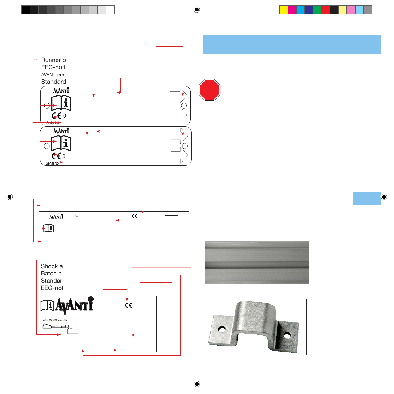
p) The runner shall be handed out and treated as a personal protection
equipment.
q) The weight of the user, excluding tools and equipment, shall not
be less than 40 kg. The weight of the user, including tools and
equipment, shall not exceed 136 kg.
r) The maximum number of multiple users in the ladder system is 3.
The fall arrester must be attached to no more than one personal
fall-arrest system.
s) In the rst two meters above the ground level, the user may not be
protected against hitting the ground if a fall occurs. Other additional
safeties shall be provided for this purpose.
t) Prior to the rst use of the FPS, a certied technician must inspect
and approve the complete FPS.
u) If oil, grease or the like has leaked onto the safety rail – wipe it off.
v) If oil, grease, chemicals or the like has leaked onto the shock
absorber or in any kind been in contact with the webbing, have an
AVANTI FPS certied technician replace the shock absorber.
w) The shock absorber has a limited life. Its date of expiration is printed
on the shock absorber label.
x) The operation temperature of the FPS is -30º / +60º Celsius.
y) The FPS shall only be used in connection with a full body harness
that is approved according to EN 361.
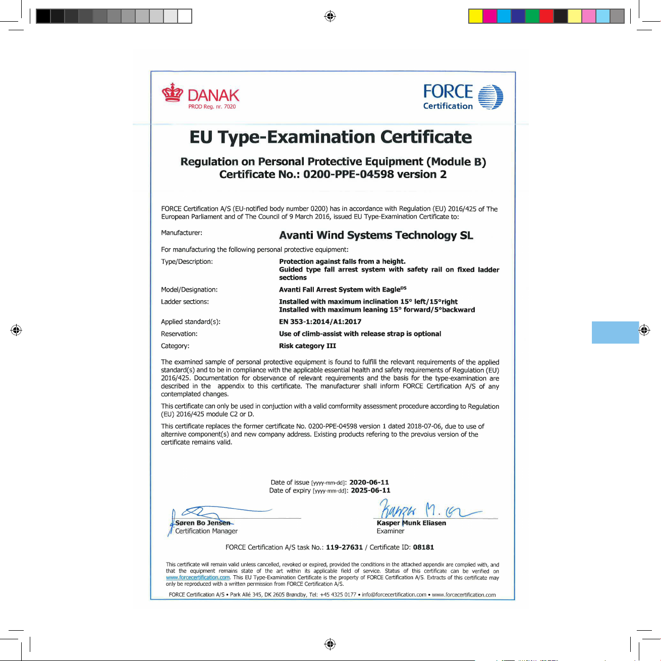
z) The FPS has been tested and approved according to
EN 353-1:2014+A1:2017.
aa) The type-examination of the FPS has been performed by: FORCE
Certication A/S, EC Notied Body 0200, Park Allé 345, DK-2605
Brøndby.
ab) The production control of the FPS is performed by the same notied
body.
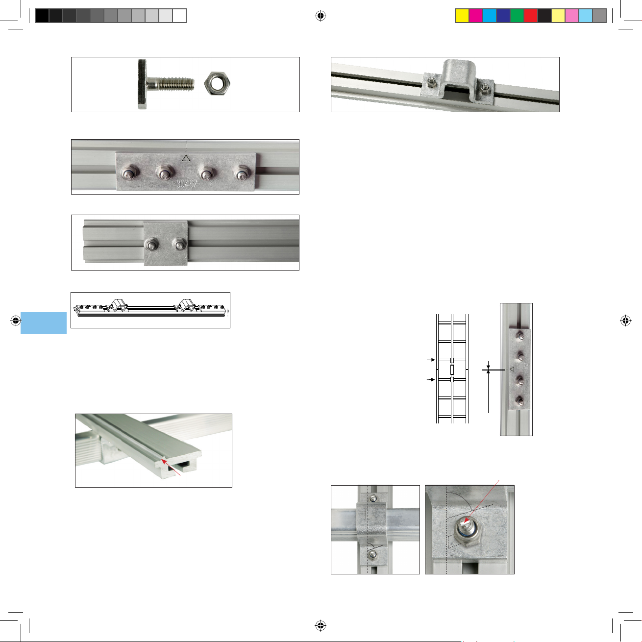
ac) These instructions shall be kept together with the permanent
installed parts of the FPS (i.e. the rail system).
Owner shall verify the need for FPS inspections with the local
authority and comply with the standards specified.
ad) When working at heights, the user shall minimise both the risk of
potential falls and the potential fall distance.
ae) In order to avoid collisions with the ground or obstacles should
a fall occur, the user shall verify the free space required beneath
his/her actual position taking into account sharp edges, electrical
conductivity and pendulum falls.
af) The safety of the users depends upon the continued efciency and
durability of the FPS. Thus, regular periodic inspections shall be
carried out, minimum every 12 months.
ag) All the FPS parts have been especially developed and tested for
AVANTI´s FPS. Thus, they shall not be used as part of other Fall
Protection Systems.

8
3 Description of equipment
3.1 Purpose
a) The FPS is intended for use during ascent and descent on stationary
ladders installed in towers, pylons, well shafts, or alike.
b) The FPS is a safety system that arrests a fall of the user during
climbing.
c) The runner travels along a safety rail.
d) The safety rail is designed for permanent installation at one place.
e) The safety rail can be installed on ladders of different shapes and
brands as long as an approval is issued before by AVANTI.
f) The FPS is not designed for securing horizontally or for securing
equipment. The FPS shall never be used for work positioning or for
securing equipment. If work positioning at the ladder is required, a
separate dedicated and approved work positioning equipment shall
be used.
g) The FPS may not be used outside its limitations, or for any purpose
other than that for which it is intended.
3.2 Function
a) The user attaches the runner to the designated D-ring marked “A” in
the front of his full body harness by means of the integrated shock
absorber and the carabiner. (In case of two D-rings marked “A” in
the front of full body harness, both rings act together like an only
point of attachment, do not individually).
ah) The combination of FPS parts in anyway other than the intended
will jeopardize safety. Thus, the FPS parts shall not be combined in
anyway other than the intended.
ai) The FPS shall never be adapted, extended, or changed in any way.
b) Before starting to climb, the user clicks the runner on the safety rail
and checks its locking.
c) When climbing, the runner glides along the safety rail. In case that
the user experiences a fall, the runner will lock on the safety rail and
arrest the person falling.
3.3Component overview
a) The FPS comprises the rail system and the runner system.
Raíl
Rung tting
Runner
Shock
Absorber
Carabiner
b) The safety rail system comprises: the safety rail sections, the rung
ttings, the top and bottom rail-stops, the sh-joints, hammerhead
screws and self-locking nuts.
c) The runner comprises: the runner itself, the shock absorber, and the
carabiner.
d) There are two runner models covered in this manual: Runner
2000/2002 and EagleDS Runner. Both models t the AVANTI rail.
Runner 2000/2002
EagleDS Runner

9
System 2000/2002 EN 353-1/A1:2017 CSA Z259.2.1-98
Eagle DS EN 353-1/A1:2017 CSA Z259.2.4-15
Harness EN 361 ANSI Z359.11 CSA Z259.10
Read supplied instructions prior to use. Min.distance 6 m (19.7 feet) between users.
Maximum number of users: 3. Systems must be inspected by a certified AVANTI technician
annually under normal use or inmediately in the event of a shock load as a result of a fall.
Only AVANTI replacement parts may be used with the system.
www.avanti-online.com
P: (+34) 976149524
Production date:
Serial No.:
WARNING
Using replacement parts,
components not approved by
AVANTI or modified runners with
the rail system could result in
serious injuries or death.
Use of Personal Protective
Equipment is mandatory
FOLLOW ALL INSTRUCTIONS
0200
Date of commissioning:
Eagle DS
EN 353-1/A1:2017
Type: Rail Mount Size: AVANTI Fall Protection Rail Only. Read and follow all
instructions before use. Inspect device prior to each use.
User weight:
40 - 136 kg
Serial No.: Production date:
www.avanti-online.com
P: (+34) 976149524
UP
0200 UP
0200
Avanti Shock Absorber CE
for Avanti Fall Arrest System
EN 353-1/A1:2017
No: Expire:
Runner 2000/2002
EN 353-1/A1:2017
Type: Rail Mount Size: AVANTI Fall Protection Rail Only. Read and follow all
instructions before use. Inspect device prior to each use.
User weight:
40 - 136 kg
Serial No.:
www.avanti-online.com
P: (+
34
)
976149524
Production date:
UP
0200 UP
Runner rating plate
Upward direction when mounted onto rail
Read instructions before use
Runner production no.
EEC-notied body no.
AVANTI product name (Runner System 2000/2002 or EagleDS)
Standard no.
3.4Marking
Shock absorber label
Max distance between runner and harness 0,3 m
Shock absorber expiration date
Batch no.
Standard EN no. for shock absorber
EEC-notied body no.
Safety rail rating plate
EEC-notied body no.
Standard no.
Production batch no.
Read instructions before use
4 Installation
4.1 Installation requirements
A certified technician shall be in charge of the FPS installati-
on. The certified technician shall take full responsibility for the
installation and shall guarantee that it is done in accordance
to these instructions.
a) The FPS shall only be installed with original system parts.
b) All FPS elements shall be checked on site, even if the ladders are
supplied with the rails already tted.
c) The vibrations and torsional stress are absorbed by the ladder
joints, not by the safety rail.
d) Ensure that the ladder intended for mounting the FPS complies
with the requirements of EN 131 and EN ISO 14122. The internal
rung width shall be minimum 340mm (all AVANTI ladders meet this
requirement).
e) The ladders with rung geometries different to AVANTI‘s may call
for special rung ttings. Prior to installation, these ladders shall be
calculated, tested and approved by AVANTI.
f) Before installing the rail system, ensure that all parts are present.
Refer to the parts list supplied with the FPS.
g) The ladders shall be installed vertically with a maximum inclination
of -5º / +15º.
h) The parts of the safety rail system to be installed are shown below.
STOP
Rung tting
Safety rail section (backside)

10
Hammerhead bolt with self-locking nut
Fish joint connector
Sample of rail-stop to be used at top and bottom of the rail installation
Flange connection kit
4.2 Installation of the rail system on the ladder
a) Place the safety rail on the centre and front side (the climber´s side)
of the ladder.
b) Place the safety rail so that the guide seat is situated on the left side.
c) Fix the safety rail to the ladder by means of the rung ttings.
d) Mount the rung ttings using hammerhead screws and self-locking
nuts, and following the instructions below.
Guide seat
The guide seat is meant to prevent incorrect orientation of the runner.
The guide seat must be situated on the left side.
A rung tting mounted on the rail
i. For each rail section, mount a rung tting on the rst (lowest) rung of the
ladder.
ii. For each rail section, mount a rung tting on the last (highest) rung of the
ladder. This is also necessary even if the second or third last rung of the
ladder are mounted with a rung tting.
iii. For each rail section, mount a rung tting at least every third rung, never
leaving more than 2 consecutive rungs without a rung tting.
iv. For each rail section, mount at least 4 rung ttings to the ladder. When
rail section is connected to another rail section, the sh joint can be also
considered as a rung tting connection.
e) Use a sh-joint to join 2 consecutive safety rail sections.
f) Use 4 screws to mount each sh-joint.
g) Leave a gap between 2 consecutive safety rail sections of at least 1 mm
and maximum 4 mm.
h) Place the hammerhead screws with the indicator marks in an angle of 70°.
i) Tighten all the self-locking nuts to 8 Nm and ensure that they sit with the
70º angle.
Angle of the indicator marks and of the self-locking nuts
Indicator mark
70°
70°
1 mm ≤ x ≤ 4 mm
Bottom rung of a
ladder section
Top rung of a
ladder section

11
j) Use the supplied self-locking nuts at all times.
k) Ensure that each screw extends from the nut by at least half of the
thread diameter, or by at least 2 threads (apply the most restrictive
requirement).
A rail-stop shall be installed at the top and bottom of the rail, and
at any provisional point where the runner can unintentionally run
off the rail.
l) Mount the top and bottom rail-stops on the safety rail, at the highest
and lowest travel points respectively.
m) The distance between top rung and the top end of the safety rail shall
not exceed 100 mm. The distance between the bottom end of the
safety rail and the ladder bottom/oor level shall not exceed 600 mm.
n) During the erection phase of the wind turbine tower sections (i.e. when
the tower sections are being connected vertically), a top rail-stop shall
be mounted on the safety rail at the highest point of each tower sec-
tion. This way, the technicians will be able to use the FPS during this
phase.
o) If the safety rail and the ladder are installed in a wind turbine tower
section before the tower is erected, their nal position shall be adjusted
during the tower erection.
4.2.1 Safety rail at the tower flange connections
a) A rung tting shall be mounted on the penultimate top and penultimate
bottom ladder-rung of each tower section (i.e. at tower ange connec-
tion).
b) The top end of the safety rail of each tower section shall end minimum
55 mm and maximum 100 mm above the second top rung tting.
STOP
Top
rail-stop Maximum
100 mm Bottom
rail stop
Bottom rung of the
complete tower
Maximum 600 mm
Floor
Top rung
of the
complete
tower
c) The bottom end of the safety rail of each tower section shall end mini-
mum 55 mm and maximum 100 mm below the rung tting.
d) The safety rails of two consecutive tower sections shall be connected
by means of a ange connection kit.
e) The distance between the safety rails of two consecutive tower sec-
tions shall be equal or less than the length of the ange connection kit.
Length limits of the top and bottom ends of the safety rail
Bottom rung of
a tower section
Tower ange
Top rung of a
tower section
55mm ≤ x ≤ 100mm
55mm ≤ x ≤ 100mm

12
5 Inspection before the first use
7 Instructions for use
6 Daily inspection
a) Before using the runner, perform a daily inspection following the “Daily In-
spection Checklist for Runner 2000/2002” Appendix or the “Daily Inspection
Checklist for EagleDS Runner” Appendix. If any of the checks does not pass,
the runner system cannot be used.
b) During the ascent, look for visible damages or loose parts such as loose screws
on ladder, rail or joints.
c) Equipment with defects or equipment that leaves doubt concerning safe use
must be checked by a certied technician.
Do not use the FPS if it looks defective or if parts are missing.
If the FPS has blocked a fall or has been put out of service
because of doubts, it may only be put back to service after an
inspection by a certified technician is performed. The certified
technician shall confirm in writing that the FPS is found in safe
condition to be used again.
STOP
The Avanti fall arresters could be lubricated with a high performance
grease, for instance HTS+PTFE ABSOBON (Würth) or ISOFLEX
TOPAS L32 N (Klüber), for cold conditions. Any grease to be used in
Avanti fall arresters must be verified and approved by Avanti.
7.1 Instructions for use of Runner 2000/2002
7.1.1 Attaching the Runner 2000/2002 to the safety rail
Before using the runner, make sure that you are wearing an approved
full body harness, and that it is properly adjusted to a snug fit (it
should not be used if loose). Before attaching the runner to the rail,
ensure that you are in a safe area (ground level) or attached to an
alternative fall protection.
Before attaching the runner to the rail, ensure that it is attached to the
D-ring marked “A” of the full body harness in order to avoid dropping it.
The carabiner shall only be connected to the D-ring marked “A” of the
full body harness located on the front side of the user and located at
the chest height.
The D-ring marked “A” shall comply with the demands for climbing in
vertical fall arrest safety systems on ladders (see the user´s manual of
the full body harness).
When attaching the carabiner, ensure that the shock absorber is
not twisted between the runner and the carabiner. A twisted shock
absorber may cause the FPS to fail.
a) Place the runner on the
safety rail ensuring that the
arrow on the plate of the
runner points upwards.
Otherwise, the runner will
not arrest a fall.
STOP
Before the first use, a certified technician shall inspect the
FPS.
The inspection before the first use shall be carried out fol-
lowing the inspection procedure. During the inspection, the
“Annual Inspection Checklist” Appendix and the “Inspection
log sheet” Appendix shall be filled in for future reference.
STOP
The detailed installation procedure of the flange connection
kit is available upon request to AVANTI.
Flange connection kit

13
b) Open the runner by pressing the left bottom pin and pulling apart both
body sides of the runner simultaneously.
c) While lifting the lever, tilt the runner so the runner is parallel and close to
the safety rail.
d) Push together the two body parts of the runner until the left bottom pin
pops out. You will hear a click sound.
e) Make sure the runner is locked correctly by pulling the lever
downwards and conrming that the runner locks on the rail.
f) Climb the ladder keeping a distance of minimum 10 cm between torso
and ladder. This distance guarantees an optimal operation, enhanced
safety and better climbing ergonomics.
g) During ascent or descent, keep a minimum distance of 6 meters
between each user.
If the full body harness becomes loose during ascent or
descent, it should be correctly adjusted again from a secured
position.
Each rail section shall only be used by one user at a time, since
having more users using the same rail section simultaneously would
jeopardise its structural resistance.
Engaging the release mechanism of the runner during ascent or
descent can jeopardise the function of the braking mechanism.
The FPS is only approved as a fall arrest safety when ascending
or descending the ladder. Thus, the FPS shall never be used for
work positioning or for securing equipment. If work positioning at
the ladder is required, a separate dedicated and approved work
positioning equipment shall be used.
STOP
STOP
7.1.2 Releasing the Runner 2000/2002 from the safety rail
a) Before stepping in or stepping off the ladder, attach alternative
fall protection.
Before releasing the runner from the rail, ensure that you are in a
safe area (ground level) or attached to an alternative fall protection.
Before releasing the runner from the rail, ensure that the runner is
without load and that there is no risk of falling.
Before releasing the runner from the rail, ensure that it is attached
to the D-ring marked “A” of the body harness in order to avoid
dropping it.
b) Release the runner from the rail by pressing the left bottom pin and
pulling the runner body parts apart simultaneously.
c) Remove the runner from the rail. It is not intended to be parked on the
rail. The runner is personal and shall be in reach in case of an emergency.
If any damages or faults are found during operation, or any other
circumstance which may jeopardise safety: immediately stop the
work in progress, and contact the site responsible, e.g. the turbine
owner or the site foreman.
7.2 Instructions for use of EagleDS Runner
The cautions listed previously for Runner 2000/2002 are equally
applicable to EagleDS Runner. Follow them closely.
7.2.1 Attaching the EagleDS Runner to the safety rail
a) Pull out the plunger and rotate the locking lever downwards (see
images below).
STOP
STOP
STOP

14
b) Open the runner by pressing
the right button and pulling apart
both body sides of the runner
simultaneously.
c) Place the runner on the safety rail ensuring that the arrow on the plate
of the runner points upwards.
d) While lifting the lever, tilt the runner so the runner is parallel and close to
the safety rail.
e) Push together the two body
parts of the runner until the
push button pops out and you
hear a click.
f) Pull out the plunger and rotate the locking lever upwards (see images
below).
g) Make sure that the runner is locked correctly by pulling the lever
downwards and conrming that the runner locks on the rail.
h) Climb the ladder keeping a distance of minimum 10 cm between torso
and ladder. This distance guarantees an optimal operation, enhanced
safety and better climbing ergonomics.
i) During ascent or descent, keep a minimum distance of 6 meters
between each user.
Arrow

15
7.2.2 Releasing the EagleDS Runner from the safety rail
a) Pull out the plunger and rotate the lever downwards to the horizontal
position (see images below).
b) Press and hold the push button.
c) Open the runner by pressing the push button and by pulling apart both
body sides of the runner simultaneously (see image below).
d) Remove the runner from the safety rail.
8.1 Cautions
a) Keep all the parts free of oil, grease, paint, aggressive chemicals
and alike.
b) Clean the shock absorber using a weak sulpho-solution and a soft
brush. Subsequently, ush it with plenty of pure water.
c) Never place liquids or sharp objects in the vicinity of the FPS as
these might damage it.
d) If the FPS gets wet, dry the runner and the safety rail with a dry
cloth. Let the shock absorber air-dry naturally. Do not use any kind of
heating.
8.2 Storage
a) Store the runner system out of direct sunlight and protected from
heat and dust.
8.3 Annual inspection
a) At least every 12 months, a certied technician shall inspect the
FPS (both runner and rail). Otherwise, the warranty will be void and
AVANTI will renounce all liability and claims that may appear.
The annual inspection may only be conducted by a certified
technician.
The annual inspection shall be carried out following the
inspection procedure. During the inspection, the “Annual
Inspection Checklist” Appendix and the “Inspection log sheet”
Appendix shall be filled in for future reference.
b) During this inspection, special attention shall be paid to the safety
rail and the runner
8.4 Inspection procedure
8.4.1 Ladder rungs
a) Ensure that no dents, holes, or cracks have any inuence on the
rung stability.
b) The dents shall not exceed 10 mm in diameter or be more than 1
mm deep.
c) If dents are found on the rung edges or corners, the step stability
can no longer be guaranteed. In such case, replace the ladder section.
STOP
STOP
8 Maintenance
Caution!
The locking lever is only to be used when locking or unlocking/
releasing the runner. In all other situations the locking lever shall
be kept in locked position fixed with the plunger locked in the
runner body.

16
8.4.2 Ladder stiles
a) Ensure that no dents, holes, or cracks have any inuence on the stiles´
stability.
b) The dents shall not exceed 20mm in diameter or be more than 1 mm
deep.
c) If dents are found on the stile edges or corners, the stile stability can no
longer be guaranteed. In such case, replace the ladder section.
8.4.3 Flange connection kits
a) The distance between the rungs at tower ange connection shall be
minimum 255 mm and maximum 300 mm.
8.4.4 Ladder ends
a) On the top and bottom ends of the complete ladder system, a
protection guard (such as the AVANTI rubber feet or end cap) shall be put
in place on the stiles.
8.4.5 Safety rail
a) Ensure that the safety rail sections are mounted according to the
installation instructions of this manual.
b) Ensure that no sharp rail ends are present.
c) Check the legibility of the product marking. If marking is not present, a
certied technician shall replace them.
d) During the erection of the wind turbine towers, top and bottom rail-
stops shall be mounted on each individual tower section.
e) Ensure that top and bottom rail-stops are mounted.
8.4.6 Fish-joints
a) Ensure that the sh-joints are mounted with 4 hammerhead screws.
b) Ensure that the gap between consecutive safety rails is minimum 1mm
and maximum 4 mm.
c) Ensure that the indicator mark of each hammerhead screw and the
self-locking nuts are at an angle of 70º.
d) Make sure that all hammerhead screws and self-locking nuts of the rail
system are present and torqued to 8 Nm.
8.4.7 Circular inspection sticker
a) Ensure that the sticker is present and that the due date has not
expired.
8.5 Ordering spare parts
a) If any part of the FPS is found to be broken, unsafe or missing,
put the FPS out of service immediately.
b) Subsequently, contact an AVANTI representative to replace/
repair the missing parts.
c) Finally, a certied technician shall carry out an inspection
following the inspection procedure.
1
|
2
|
3
|
4
|
5
|
6
|
7
|
8
|
9
|
1
0
|
1
1
|
1
2
|
1
8
|
1
9
|
2
0
|
2
1
|
2
2
|
2
3
|
NEXT
INSPECTION

Type of AVANTI Runner: Runner 2000/2002 or Eagle DS User´s name:
Standards: EN353-1 / RfU11.073 / AS/NZS1891.3 Phone:
Tower (WEA-No.): Name of inspector:
Date of inspection: Date of next inspection:
1Ladder system OK NOK COMMENTS
1.1 Rungs Are dents less than 10 mm in diameter or 1 mm deep?
Are the rung ends xed tight to the stiles?
Are the rungs free of cracks?
1.2 Stiles Are dents less than 20 mm in diameter or 1 mm deep?
Are the stile ends free of dents?
Are the stiles free of cracks?
1.3 Flange connection kits Is the distance between the rungs of consecutive ladder sections at tower flange between 255 and 300 mm?
1.4 Ladder ends Are the AVANTI rubber feet or end caps mounted?
1.5 General Is the ladder system free of dirt (oil, corrosion, paint, etc.)?
2 Safety rail system OK NOK COMMENTS
2.1 Safety rail sections Are the safety rail sections mounted on the front side?
Is the guide seat of each safety rail section placed on the left side?
Are the ends of each safety rail section free of sharp edges?
2.2 Rung tting Is there a rung tting on the rst (lowest) rung of each ladder section?
Is there a rung tting on the last (highest) rung of each ladder section?
Is there a rung tting on at least every third rung of each ladder section?
Is each rung tting free of damages?
2.3 Fish-joints Is each sh-joint mounted with 4 hammerhead screws?
Are all the indicator marks of the hammerhead screws and the self-locking nuts at an angle of 70º?
2.4 General Is the safety rail system free of dirt (oil, corrosion, paint, etc.)?
Is the safety rail system free of damages?
3Others OK NOK COMMENTS
3.1 Resting platforms Are the resting platforms in place and xed properly?
3.2 Screws Are all the screws in place and torqued properly?
3.3 Labels and markings Are all the labels and markings legible?
4Runner system OK NOK COMMENTS
4.1 - Is the runner approved for use?
5Final assessment OK NOK COMMENTS
5.1 - Is the FPS approved for use?
This inspection shall be carried out before the rst use and at least every 12 months by AVANTI or by a
certied technician. This checklist and the Inspection log sheet shall be lled in and led for future reference.
Inspector´s Signature:
Appendix A: Annual inspection checklist

ISSUE DESCRIPTION PASS FAIL
1Is the runner´s body free of corrosion, deformation and other
damages? (See Fig. 1)
COMMENTS
2Is the brake lever free of corrosion, deformation and other dama-
ges? (See Fig. 2)
COMMENTS
3Is the middle plate tightly attached by the 4 xed rivets? (See Fig. 3)
COMMENTS
4Is the middle plate free of deformation? (See Fig. 3)
COMMENTS
5Is the aluminium serial plate tightly attached by the 2 xed rivets?
(See Fig. 4)
COMMENTS
6Are the synthetic guides tightly seated and without bruises and
marks? (See Fig. 5)
COMMENTS
7Is the blank aluminium plate present and sitting tight? (See Fig. 6)
COMMENTS
8Does the shock absorber show a normal shape? Are the absorber
and the cover free of cuts, burns, seams and visible signs of wear?
(See Fig. 7)
COMMENTS
ISSUE DESCRIPTION PASS FAIL
9Is the carabiner free of marks, deformities, wear and traces of corro-
sion? (See Fig. 8)
COMMENTS
10 Is the return spring and articulation of the carabiner opening, closing
and locking properly? (See Fig. 9)
COMMENTS
11 Does the black strap of the shock absorber cover the carabiner end
completely? (See Fig. 10)
COMMENTS
12 Does the runner close and open easily without friction or resi-
stance? (See Fig. 11)
COMMENTS
13 Does the brake lever move up and down smoothly? (See Fig. 12)
COMMENTS
14 Is the spring securely attached? Is it retracting the lever automati-
cally? (See Fig. 12)
COMMENTS
15 Is the shackle securely attached and free from marks, deformities,
wear and traces of corrosion? (See Fig. 13)
COMMENTS
16 Does the runner slide smoothly along the rail? (See Fig. 13)
COMMENTS
17 Is the circular inspection sticker present? Has the due date for
annual inspection not expired? (See Fig. 12)
COMMENTS
Appendix B: Daily inspection checklist of Runner 2000/2002
1
9
2
10
3
11
4
12
5
13
76
8
VISUAL TEST

Appendix C: Daily inspection checklist of EagleDS Runner
1
8
2
9
3
10
4
11
5
12
6
13
7
14
VISUAL TEST
ISSUE DESCRIPTION PASS FAIL
1Is the runner´s body free of corrosion, deformation and other
damages? (See Fig. 1)
COMMENTS
2Is the brake lever free of corrosion, deformation and other dama-
ges? (See Fig. 2)
COMMENTS
3Does the locking lever lock and unlock correctly? (See Fig. 3)
COMMENTS
4Does the push button move up and down correctly? (See Fig. 4)
COMMENTS
5Is the aluminium serial plate tightly attached by the 2 xed rivets?
(See Fig. 5)
COMMENTS
6Are the 6 rollers tightly placed and free of bruises and marks? (See
Fig. 6)
COMMENTS
7Is the circular inspection sticker present? Has the due date for
annual inspection not expired? (See Fig. 4)
COMMENTS
8Does the shock absorber show a normal shape? Are the absorber
and the cover free of cuts, burns, seams and visible signs of wear?
(See Fig. 7)
COMMENTS
ISSUE DESCRIPTION PASS FAIL
9Is the carabiner free of marks, deformities, wear and traces of corro-
sion? (See Fig. 8)
COMMENTS
10 Is the return spring and articulation of the carabiner opening, closing
and locking properly? (See Fig. 9)
COMMENTS
11 Does the black strap of the shock absorber cover the carabiner end
completely? (See Fig. 10)
COMMENTS
12 Does the runner close and open easily without friction or resi-
stance? (See Fig. 11)
COMMENTS
13 Is the shackle tightly attached and free of marks, deformities, wear
and traces of corrosion? (See Fig. 12)
COMMENTS
14 Does the runner slide smoothly along the rail? (See Fig. 13)
COMMENTS
15 Do the torsion springs work properly (i.e. the lever can be moved
up and down smoothly)? (See Fig. 12) Are they securely attached?
(See Fig. 14)
COMMENTS
This manual suits for next models
2
Table of contents
Popular Safety Equipment manuals by other brands

IKAR
IKAR ANCHORAGE SLINGS Instructions for the use and inspection records

Newtec
Newtec FALLSTOP INFORMATIVE NOTE

Leuze
Leuze MLC 100 Series operating instructions

ultraMEDIC
ultraMEDIC ultraHEAD-LOCK II operating manual

FTC
FTC GRAPPIN Use and maintenance instructions

Clevertronics
Clevertronics LP CWELED-WM Series Installation & maintenance instructions