AVer VC520 Pro2 User manual


English ........................................................................................................1
繁體中文....................................................................................................10
简体中文....................................................................................................20
日本語 .......................................................................................................29
한국어 .......................................................................................................38
Français ....................................................................................................47
Español .....................................................................................................57
Pусский.....................................................................................................67
English-1
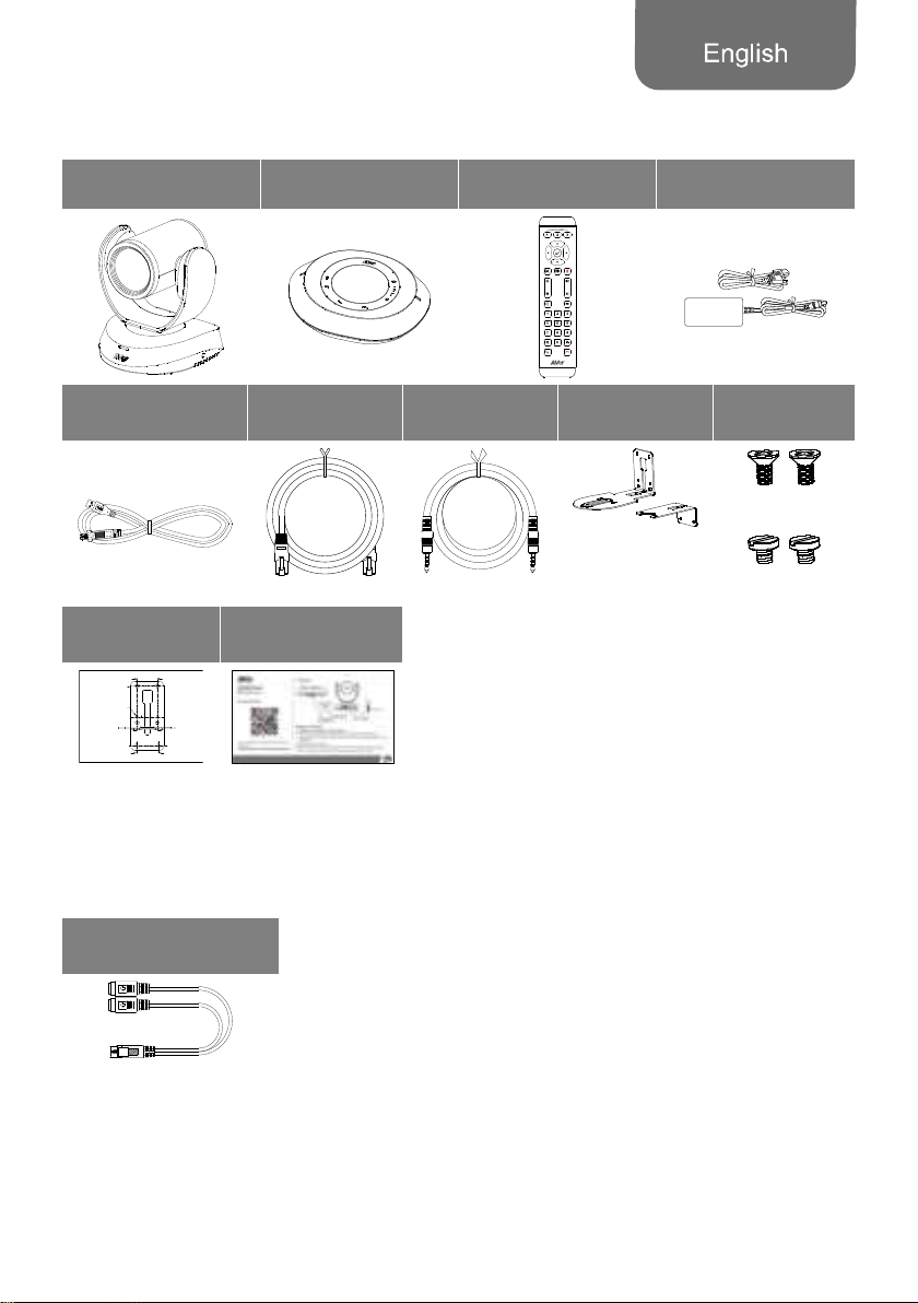
Package Contents
Camera Unit Speakerphone Unit Remote Control Power Adapter &
Power Cord*
USB 2.0 Type-B to
Type-A Cable (5m)
Speakerphone
Cable (10m)
3.5 mm Audio
Cable (0.9m)
L-Mount
Brackets
Screws for
Mount
M4 x8mm (x2)
1/4”-20
L=7.5mm (x2)
Drilling Paper QR Code Card
P/N: 303AU340- AGR
46.00[1.81]
51.00[2.01]
Ø5.5 0[Ø0.22 ]
* The power cord will vary depending on the standard power outlet of the country where it is sold.
Optional Accessory
Mini DIN9 to Mini DIN8
RS232 Adapter Cable

English-2
Overview
1
234 5 6 78
1 Status LED 4 USB 3.1 Type B Port 7 Ethernet Port
2 IR Sensor 5 RS232 In/Out Port 8 Kensington Lock
3 Speakerphone Port
(Blue Cable)
6 DC 12V Power Jack
91011 12 13
9 Speakerphone Port
(Red Cable, for extended
speakerphone and
microphone connection)
10
11
12
13
Phone In port
Line Out port
Camera Port (Blue Cable)
Kensington Lock
English-3
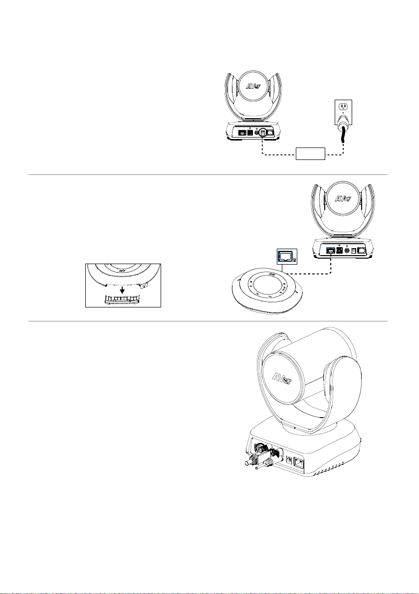
Installation
1. Connect the camera to power outlet.
Power cord
Power adapter
2. Connect the camera to the speakerphone
using the included compatible cable.
[Notes]
Both speakerphone and camera ports are
marked in blue.
Remove the back cover of the speakerphone to
connect the speakerphone cable.
Speakerphone
cable
3. Connect the necessary cables.
[Notes]
Secure the USB and RS232 cables with
attached screws. RS232 cable is an optional
accessory; please purchase from the AVer.
Make sure the cable is well connected to the
connector on the camera before securing the
cable.

English-4
4. Connect the camera to the
computer/laptop.
[Notes]
Use the USB 2.0 cable included in the package.
VC520 Pro2 has the USB 3.1 port which is USB
2.0 compatible.
Maximum resolution/fps for USB 2.0 and USB
3.1 port are shown below.
M-JPEG/
fps
NV12/fps YUV/fps
USB
2.0
1080@
60 fps
720p@
10 fps
480p@
30 fps
720p@
10 fps
480p@
30 fps
USB
3.1
1080p@
60 fps
1080p@
30 fps
1080p@
30 fps

English-5
Remote Control
Camera Select
Camera Directional
Control
OSD Menu*
SmartFrame
Zoom In/Out
Preset
Call/Answer
Brightness -
Enter*
Mute/Un-mute
VolumeUp/Down
PresetHotKey
PresetPosition
Hangup
Brightness+
*Not support for VC520 Pro2
AAA Batteries (required)
Preset ( ): The Preset button on the
remote serves 2 functions.
To Save a Preset - Move camera to desired
position. Press and hold the preset button
until you receive the save message on the
screen. Select preset position button 0-9 to
store the current camera position. Repeat
steps if needed.
To Load a Preset - Press the preset button
and preset position button 0-9 to load a saved
camera position. Repeat steps if needed.
Press and hold the number button “ ”
for 1 second to turn on or off the WDR
function.
Press and hold the number button “ ” for
1 second to turn on or off the SmartFrame
function.
Press and hold the number button
“” for 1 second to enable or disable
RTMP streaming function.
Press and hold the number button “ ”
for 1 second to force camera to enter
sleep mode. It will cut all the video
streaming off. To wake it up, press the
button for 1 second again or press
direction button. It’s not workable while
USB streaming is on.
Camera Select ( ): If you
only have one camera and don’t need to
do custom settings, the default is
camera 1. If you press camera 2 or 3 on
the remote control, you will find your
remote can’t control your camera. In this
case, please press camera 1 on your
remote again.
SmartFrame ( ): Press for 1 second
to switch the SmartFrame function
among Manual Framing/Auto Framing/
Preset Framing modes. A message (as
figures shown) will display on the screen
to indicate the mode.
[Note] SmartFrame deploys face and
body defection technology. People
wearing masks or in side facial profiles
still can be detected. The maximum
detection distance is 7-10 meters.
Set up preset points in advance (Only for
Preset point 1-9. Preset 0 is for home
position).

English-6
Wall Mount Installation
1. Use the drilling paper included in the package to drill the holes in the wall where the user wants
to mount the camera.
2. Use the screws (not included) to secure the L-mount bracket
A
on the wall.
[Note] For cement wall: M4 x20mm self-tapping screws (x4) + Plastic conical anchor
For wooden wall: M4 x20mm self-tapping screws (x4)
3. Then, assemble the L-mount brackets
A
+
B
with 2 screws (M4 x8mm, included in the
package).
4. After assembling the L-mount brackets, use the screws (not included) to secure the lower part of
L-mount brackets on the wall.
[Note] For cement wall: M4 x20mm self-tapping screws (x2) + Plastic conical anchor
For wooden wall: M4 x20mm self-tapping screws (x2)
5. Pass the cables through the hole on the L-mount brackets and connect the cables to
corresponding connection ports.
6. Use the remaining screws (1/4”-20 L=7.5mm, included in the package) to secure the camera on
the L-mount brackets.
1 2 3
4 5
6
B
A
A
P/N: 303AU 340-AGR
46.00[1.81]
51.00[2.01]
Ø5.5 0[Ø0.22 ]

English-7
Making a Video Call
A computer is required to use this device.
1. Open your video collaboration application such as Zoom, Microsoft®Teams, Skype for Business,
Skype, Google Meet, Intel®Unite™, RingCentral, BlueJeans, V-Cube, LiveOn, CyberLink U
Meeting®, TrueConf, Adobe Connect, Cisco WebEx®, Fuze, GoToMeeting™, Microsoft®Lync™,
Vidyo, vMix, WebRTC, Wirecast, XSplit.
2. Set the VC520 Pro2 as your primary camera device in your application (Please consult your
application setup guide for details).
3. Ready to make a video call.
[Note] VC520 Pro2 is a Plug-n-Play Conference Camera. The system requires no special drivers. For
advanced setting and firmware update, please download PTZApp 2.
Making a Connection through the Browser
VC520 Pro2 has an Ethernet port for IP streaming and allows administrators to remotely control and set
up the camera via an internet access. Moreover, VC520 Pro2 also supports RTSP and RTMP functions.
For more details, please refer to user’s manual or contact our technical support.
1. Make sure the VC520 Pro2 has an internet access connection.
2. Launch PTZApp 2* ( ) and connect VC520 Pro2 to PC with USB cable.
3. The camera default IP address is 192.168.1.168. Click pencil icon ( ) to edit IP address**.

English-8
4. Click weblink icon ( )to launch Chrome page. Please enter the password (default password is
aver4321).
[Note] The browser supports:
Chrome: version 76.x or above Firefox: version 69 or above IE: Doesn’t support
5. After editting IP address, user can access web settings of the camera with only Ethernet cable
connection. Unplug the USB cable.
6. The main web screen is displayed as below.
* In PTZApp2, user can change the IP address setting of VC520 Pro2, configure the parameters of the
camera, set up AI tracking functions and some advanced image settings, pan, tilt, and zoom the
camera. Please refer to the user manual for details.
Please go to https://www.aver.com/download-center (Global & European Headquarters) or
https://www.averusa.com/business/support/ (USA) to download the PTZApp 2. After downloading,
double-click on the file and follow the on-screen instructions to complete the installation.
After installing the PTZApp 2, double-click on the PTZApp 2 icon to run the application.
** To support IP address changes in groups, user can download AVer IP Finder app.
1. Download the IP Finder from https://www.aver.com/download-center (Global & European
Headquarters) or https://www.averusa.com/business/support/ (USA).
2. Run the IP Finder.
3. Click “Search”, and all available devices will be listed on the screen.
Lo
g
out
Other manuals for VC520 Pro2
1
Table of contents
Languages:
Other AVer IP Camera manuals


