Avery Weigh-Tronix WP-250 User manual
WP-250 Ticket Printer
Service Manual

TABLE OF CONTENTS
WP-250 Service Manual............................................................................. 1
General Maintenance ........................................................................... 1
Ribbon Replacement............................................................................ 1
Removing Old Ribbon .................................................................... 1
Installing New Ribbon .................................................................... 1
Description and Location of Major Components ......................................... 2
Time and Date Option .......................................................................... 2
Installing Time and Date Option ........................................................... 2
BCD Interface Option ........................................................................... 3
Installing BCD Interface Option ............................................................ 4
Serial Interfacing .................................................................................. 5
Current Loop .................................................................................. 5
Pulse Input..................................................................................... 6
Trouble-Shooting ........................................................................................ 6
Missing Dot Troubleshooting................................................................ 7
Circuit Operation and Test Points......................................................... 7
Print Head Mechanism Replacement/Alignment Procedure ....................... 8
Removal of Print Head Carrier Assembly............................................. 8
Replacement of Assembly ................................................................... 9
Time and Date PC Board.......................................................................... 10
BCD PC Board ......................................................................................... 10
Main PC Board ......................................................................................... 11
1
WP-250 Service Manual
General
Maintenance
Ribbon Replacement
IMPORTANT: When removing
and installing the ribbon, take
care not to stain the printer
parts with ink contained in the
ribbon.
Removing Old Ribbon
Installing New Ribbon
The WP-250 Ticket Printer is designed to operate with a minimal amount of
regular maintenance. However, it is important that the printer remain clean
duringoperation.
The most critical part to be kept clean is the head shaft. The shaft should
be cleaned and fresh lubricant lightly applied two or three times a year.
(LUBRI-PLATE or IBM #23 are recommended lubricants.) The nylon gears
used in the printer do not require any lubrication.
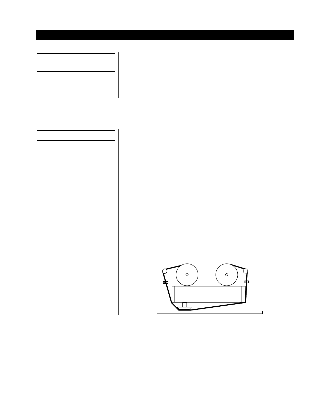
The ribbon can be changed at the user's discretion. The ribbons supplied
by Weigh-Tronix are rated for 1,000,000 characters of standard text.
Ribbon life will vary depending on usage.
1. Pull the two ribbon spools forward to separate them from the spool
drive pins.
2. Take the old ribbon off the ribbon guide of the ribbon frame.
1. Position the ribbon along the ribbon guide as shown in the illustration
below.
2. Make sure the ribbon spools have been properly seated on the spool
drive pins.

2
Description & Location Of Major Components
Time And Date Option
Installing Time and
Date Option
1. Main PC Board
There is one main circuit board which is mounted in the bottom of the
WP-250 Ticket Printer cabinet. It contains all of the power supply
circuitry except the transformer. It also contains all of the logic circuitry
except the BCD input which is an external, optional BCD board.
2. BCD Option
The BCD option is composed of an additional circuit board that
attaches to the rear of the printer. This board is attached by a cable.
Major Components
Description W-T Part #
Ticket Print Mechanism 45009-1020
Paper Feed Solenoid 45009-1061
Paper Hold Solenoid 45009-1079
Time and Date Ass'y (w/ battery) 45009-1004
Time and Date Battery Only 45009-1095
Main PC Board 45009-1087
BCD Adapter with EPROM 45009-1012
Print Switch 45009-1129
Power Transformer 45009-1095
The time and date option provides the current time and date in both a 12
hour and 24 hour version. For systems that involve an intelligent host
device that can provide the time and date, this option is not needed.
If you planned to use the Time and Date Option at the time you ordered
the WP-250, the option was probably purchased and installed before the
unit was shipped. If you purchased the WP-250 without the options, it can
be easily installed:
1. Unplug the printer from the wall outlet.
2. Remove 4 screws on the print mechanism cover and remove the
cover by lifting up.
3. Connectors J5 and J6 will be empty if the printer does not have the
Time and Date Option installed.
4. Install the Time and Date Option board with the battery close to the
front of the printer.
5. Replace the print mechanism cover to its original location. Hold the
cover in place with the four screws, which should be snug but not too
tight.
6. Perform a self-test to verify printer operation.
7. Refer to User's Manual to set the Time and Date.

3
The BCD Option is used to interface electronic weigh scales that have only
a BCD type interface. Parallel BCD is not a general data interface and does
not use the ASCII control codes. It is a numeric interface meant to obtain
the weight, units, and motion indication from electronic weigh scales.
BCD stands for Binary Coded Decimal. It was one of the first interfaces
made available for electronic weigh scales when the big push for electronic
conversion of mechanical scales began in the 1970's. The interface basi-
cally began as a latched TTL (transistor transistor logic) output of the seven
segment scale display.
The BCD Option converts a 5 1/2 active digit BCD input into a 20 mA
current loop output. The interface cable is a 29 wire conductor cable. For
each of the five digits tranferred the cable contains four wires. Digit six is a
single wire that is the 100,000 input. The other wires include the PRINT
input, the SIGN input, PRINT INHIBIT or MOTION input and LOGIC
ground. In addition, a bank of switches controls the assumed decimal place
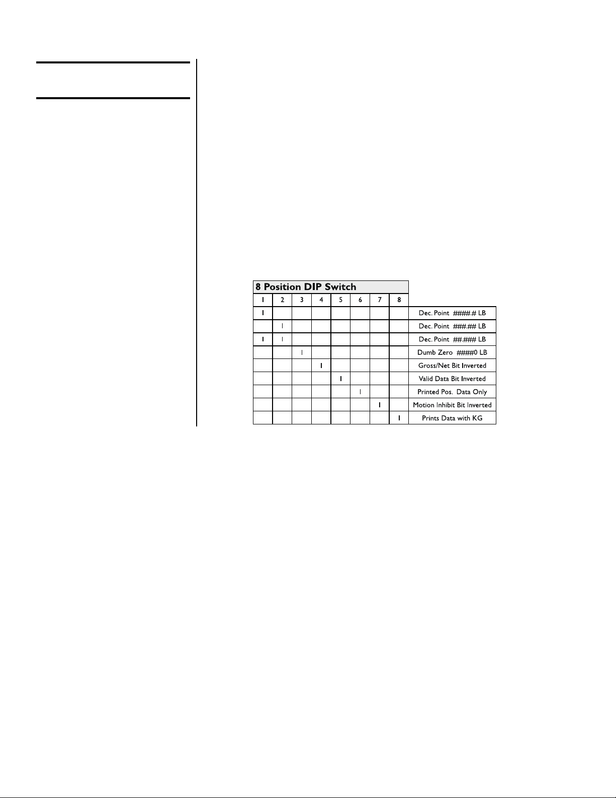
setting, the imposing of a trailing dumb zero, and kg/lb unit printing.
BCD Interface Option
4
1 = ON
# - number 0-9
For the WI-110/120 Switch 6
must be on. Switches 1, 2, 3 &
8 must be set to match your
indicator's display mode.
Installing The BCD
Interface Option
If you planned to use the Parallel BCD Interfacing at the time you ordered
the WP-250, the option was probably purchased and installed at the
factory. If you purchased the WP-250 without the option, it can be easily
installed.
1. Unplug the printer from the wall outlet.
2. Program the 8 Position DIP Switch in the BCD Module.
3. Connect the cable from the BCD interface board to the indicator.
4. Connect the cable from the BCD interface board to the printer.
5. Configure the printer for current loop 1200 baud, 8 data bits, no parity.
6. Perform a self-test to verify printer configuration and operation.

5
Serial Interfacing The RS-232C, Current Loop, RS-485, and Pulse Input are standard in
every WP-250 Ticket Printer.
The WP-250 serial input port is connector J1. It has an industry standard
DB-25 female connector wired
as a DTE device. The WP-250 has a 4000 character input buffer and
unless you plan to send more characters than this per ticket, you will not
overflow the input buffer. If you will be sending a large amount of data
or sending data continuously, as with some electronic weigh scales, you
may want to implement some type of handshaking.
The printer supports XON/XOFF handshaking. The XON/XOFF handshak-
ing requires no additional wiring to implement. The host device only needs
to support the XON/XOFF protocol.
Serial Interface Connections
PIN Signal Description
1Chassis Ground
2TXD Transmit data
3RXD Receive data
4 RTS
5CTS Clear to send
6+5R
7Ground
8+20 mA in
22 -20 mA in
15 + Pulse Input
22 - Pulse Input
16 Remote Print (active low)
13 Ground
20 DTR +8V
11 + RS-485
12 - RS-485
The 20 mA Current Loop, which is standard in the WP-250, is a good
interface for systems that will require long distances between the host
device and the printer.
Data is sent between the transmitter and receiver as a series of pulses.
The set-up of a 20 mA serial connection is much like an RS-232C inter-
face. The number of data bits, parity, stop bits, and baud rate must match
at both the transmitting and receiving ends.
The only real difference between the two is that RS-232C serial is a
voltage based interface while 20 mA serial is a current based interface.
Current Loop

6
Pulse Input:
The current for the interface is provided by one of the two devices in the
interface. The device that supplies the current is called the active side and
the device on the other end is called the passive side. It does not matter
which side is passive and which is active as long as there is only one of
each. The WP-250 has the hardware needed to be the passive side of the
20 mA interface for the receive loop.
20 mA Current Loop is frequently run on a twisted pair of wires. There is
no busy line or reverse channel for XON/XOFF for the 20 mA interface.
The connections for the 20 mA interface are on connector J1 on the back
of the WP-250 printer.
Pins 8 and 22 are the 20 mA Current Loop receiver connections.
Pulse input must be 0 - 24 VDC. A current leakage resistor may be
necessary for proper switching. The printer must be set for Current Loop
and the Intelligent Printer Mode for Pulse Input must be enabled. Be sure
to select the correct division size, decimal point place, and unit of measure
to match your indicator.
Troubleshooting
Problem Solution
1. Head will not cycle smoothly 1a. Defective drive transistors or motor, possibly 24V
supply is gone
1b. Mechanical problem. For example: gears are
binding
2. Dots missing in print 2. Defective drive transistors or printhead
3. Printing darker on one side 3. Adjust head gap (platen adjust)
4. Prints time and date but no weight information 4. Wrong baud rate, data bits, stop bits, or parity
5. Print isn't dark enough regardless of head gap 5. Replace ribbon
6. Printer locks up when PRINT button is depressed 6. Thumbwheel switch is in wrong position
7. Paper feed is inconsistent 7. Feed roller is worn
7
Missing Dot
Troubleshooting
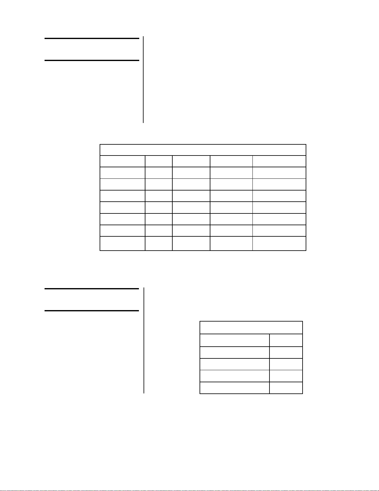
WP-255 Dot Driver Components
Dot Position Fuse Transistor Drive Diode Snubber Diode
7 F7 Q7 CR17 CR28
6 F6 Q6 CR16 CR27
5 F5 Q5 CR15 CR26
4 F4 Q4 CR14 CR25
3 F3 Q3 CR13 CR24
2 F2 Q2 CR12 CR23
1 F1 Q1 CR11 CR22
Circuit Operation And
Test Points
This table contains test points found on the main board and the voltage that
is associated with each test point. All voltage measurements are taken
utilizing signal ground located at pin 1 of U13.
Missing dots are caused by 1 or more of the following:
1. Broken needle
2. Blown transistor
3. Blown drive diode
4. Blown fuse
The table below lists the dot driver components in order of dot position.
If a dot is missing, check ALL of the dot driver components for the missing
dot.
Power Supplies
Test Point Voltage
Anode CR 31 -8 vdc
Cathode CR9 +5 vdc
Pin 3 of U13 +24 vdc
Pin 2 of U13 +8 vdc
8
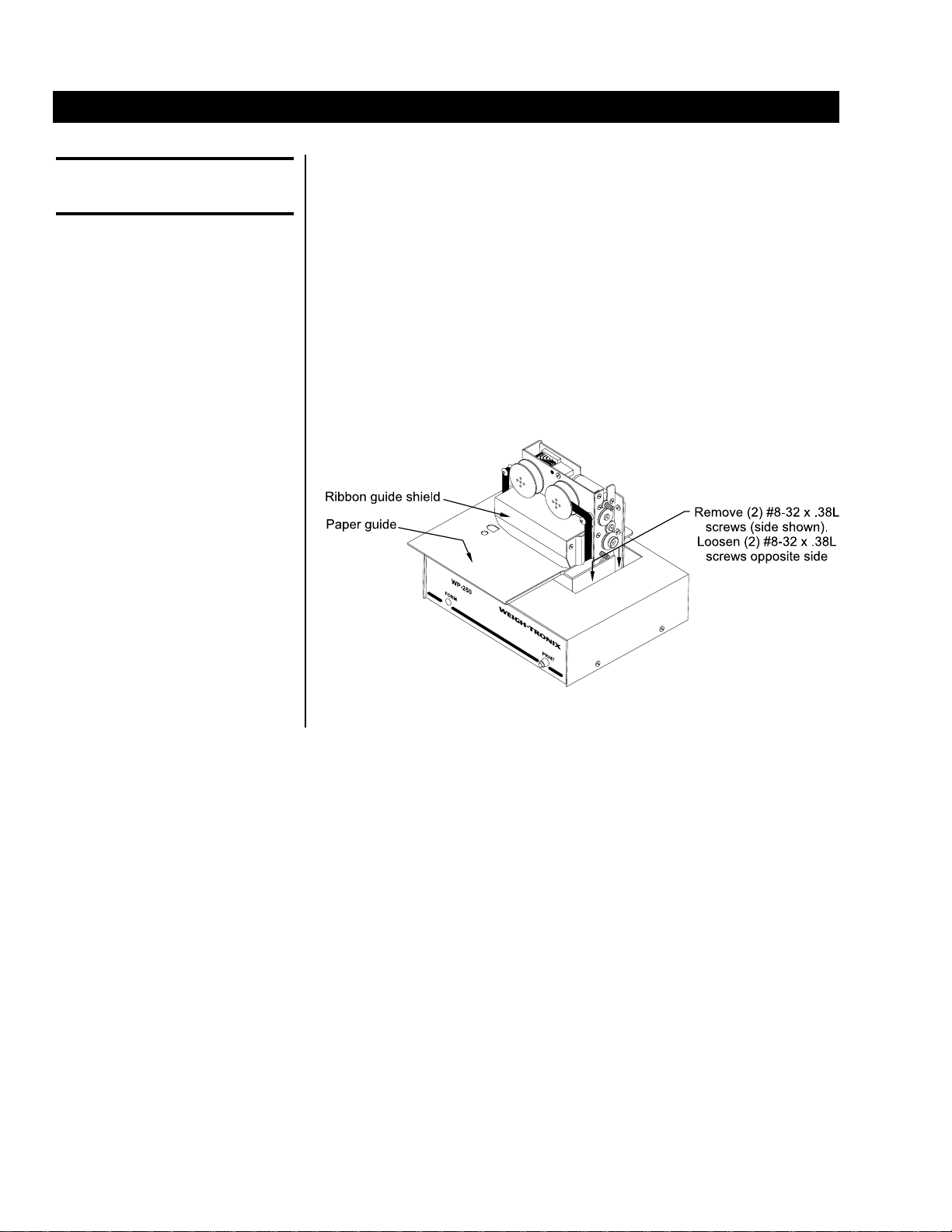
1. Remove power from the printer, then remove the ribbon.
2. While looking at the printer from the front, loosen the two screws on
the left side of the print head assembly, then remove the two screws
on the right side. (8-32 x 3/8", 4 pieces UNC) See Figure 1 below.
3. Slide the print head assembly to the right and lift up. Carefully unplug
the print head assembly.
4. Remove the four screws that hold the paper guide in place. (CS: M4 x
6, 4 pieces metric)
5. Carefully remove the two plastic pins that hold the ribbon guide shield
in place.
6. Carefully remove the ribbon guide shield.
Figure 1
Print Head Mechanism Replacement/Alignment Procedure
Removal of Print Head
Carrier Assembly
9
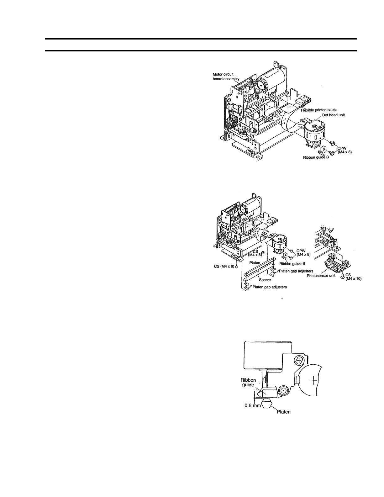
Replacement of Assembly
1. Replace the dot head unit on the print head carrier
assembly as follows:
1a. Screw the dot head unit together with the ribbon
guide assembly (B) to the print head carrier
assembly. Tighten the screws.
CPW: M4 x 8 (2 pieces metric)
1b. Plug the terminal end of the flexible cable into the
connector on the motor circuit board.
2. Install the platen as follows:
2a. Screw the spacer and platen to the frames. Install
the photosensor unit. Tighten the screws. (CS of
M4 x 10, 2 pieces metric)
If the total thickness of the sheets of paper to be
used is 0.25--0.45mm, it is not necessary to use
the spacer.
2b. By moving the print head carrier assembly from
end to end, check if the dot head unit and the
platen are parallel to each other (check if the dot
head/platen gap is of the same amount at both
ends of the print head carrier assembly).
The print head carrier should move freely from end
to end. Do not force.
3. Adjust the dot head/platen gap as follows:
3a. If the gap is appreciably different from end to end,
make adjustment by increasing or decreas-
ing the number of platen gap adjusters on one end.
3b. Move the print head carrier assembly to one end of
its stroke and make positional adjustment so that
the gap between the ribbon guide face and the
platen is 0.6mm.
3c. Move the print head carrier assembly to the
opposite end of its stroke and check the above-
mentioned gap.
10
Time and Date Board
W-T P/N 45009-1004
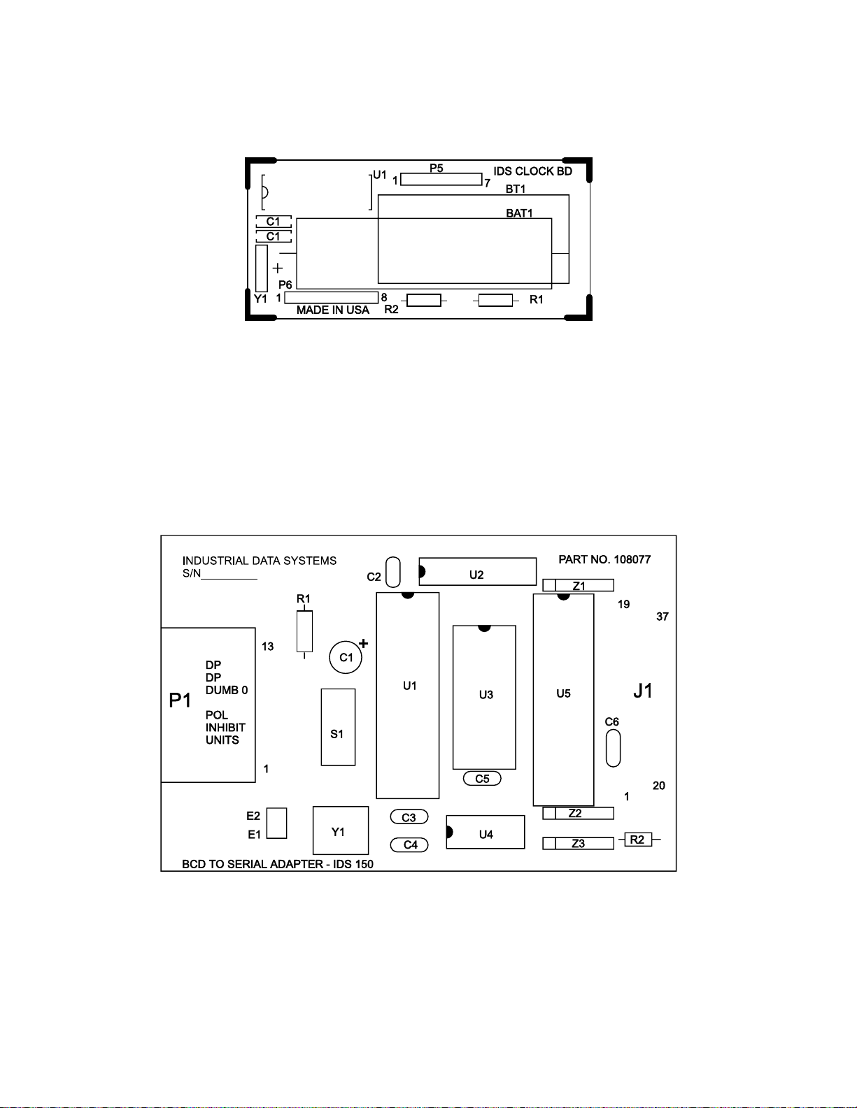
BCD Board

11
Main PC Board
W-T P/N 45009-1087

1000 Armstrong Dr.
Fairmont, MN 56031 USA
Telephone: 507-238-4461
Facsimile: 507-238-4195
e-mail: [email protected]
www.weigh-tronix.com
217 Brunswick Blvd.
Pointe Claire, QC H9R 4R7 Canada
Telephone: 514-695-0380
Facsimile: 514-695-6820
Weighing Products & Systems
Weigh-Tronix
Weigh-Tronix Canada, ULC
Weigh Bar®is a registered trademark of Weigh-Tronix Inc.
04/17/00 WP205SER.P65 PN 29549-0015e1 Printed in USA
Table of contents
Other Avery Weigh-Tronix Printer manuals

Avery Weigh-Tronix
Avery Weigh-Tronix WP-234 User manual

Avery Weigh-Tronix
Avery Weigh-Tronix ZG310 User manual

Avery Weigh-Tronix
Avery Weigh-Tronix ZG110 User manual

Avery Weigh-Tronix
Avery Weigh-Tronix WP-234 User manual

Avery Weigh-Tronix
Avery Weigh-Tronix WP-233 Series User manual

Avery Weigh-Tronix
Avery Weigh-Tronix ZG354 User manual

Avery Weigh-Tronix
Avery Weigh-Tronix TM-295 User manual


