Components of the UltraSoundGate 116Hm
7
12
Introduction
Thank you for purchasing Avisoft UltraSoundGate 116Hm This
bus-powered USB device supports single-channel high-speed data
acquisition at sampling rates of up to 1 MHz
The accompanying recording software Avisoft-RECORDER USGH
provides either continuous or triggered direct-to-disk recording with
real-time spectrogram displays
Getting started
The supplied RECORDER USGH software can be launched from
Start / All Programs / Avisoft Bioacoustics / ECO DE USGH
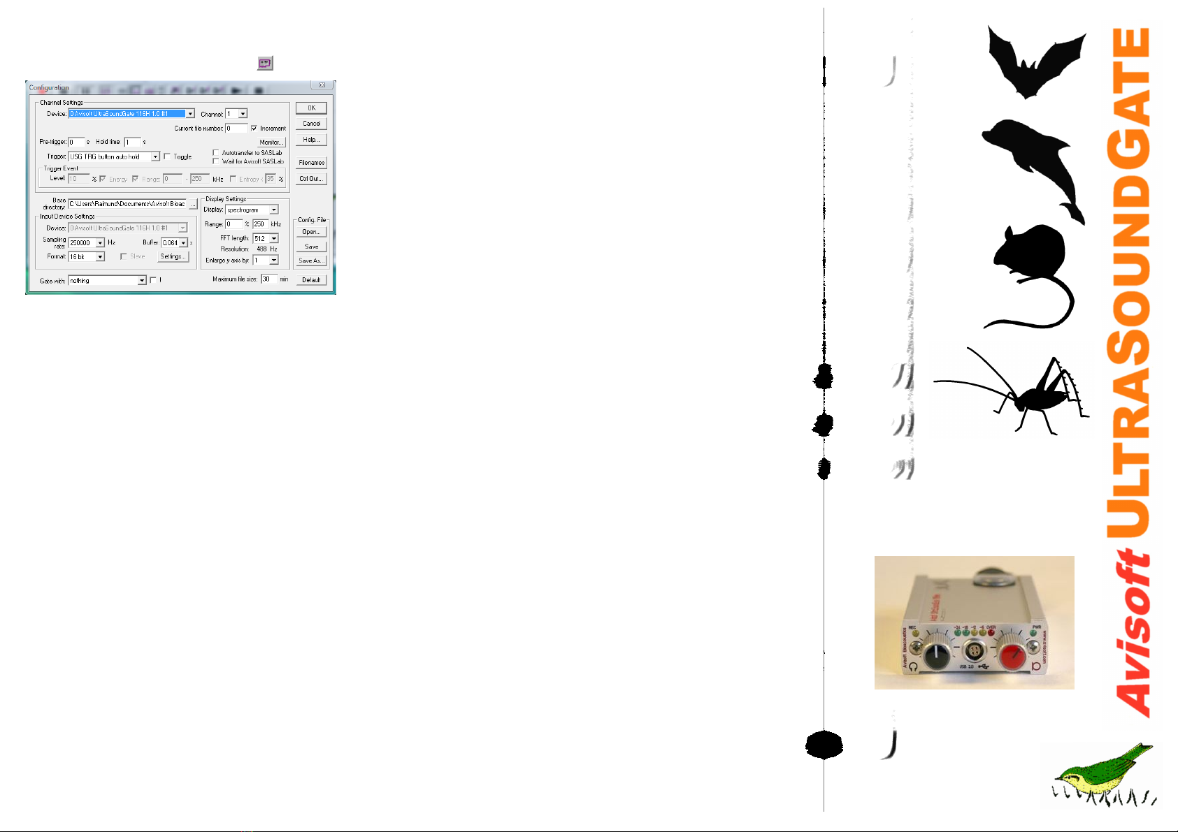
On the first program start, the configuration dialog box will be
launched automatically (otherwise it is available from Options /
Configuration). Select the desired Sampling rate from the Input
Device Settings section and click at Ok. Then click at the Pause
button (Monitoring/Pause) and the Start button (Monitoring/Start)
You will then see the real-time spectrogram displaying the incoming
signals
11
1 XL input connector
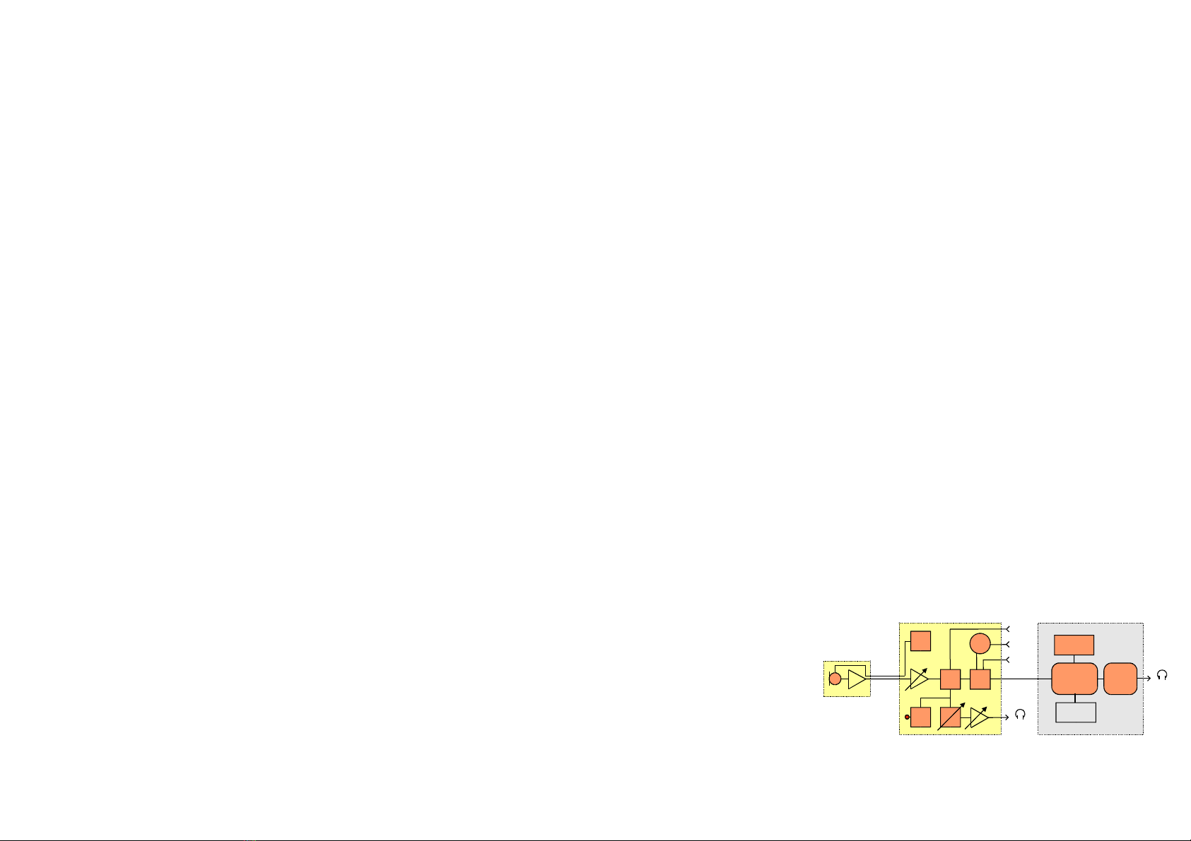
The 5-pole XLR input connector represents the analog inputs of the
recording device and provide power supply voltages for external
amplifiers and microphones The connector scheme is as follows:
2 SYNC input/output
This socket allows to synchronize the sample clock signals of several
UltraSoundGate units To accomplish this, all devices must be
connected to a single computer and one device must be configured
as the master (see section RECORDER USGH Settings for details)
3 T IGGE input/output
This 2-pole (mono) 2 5 mm mini-jack connector is electrically
connected to the TRG button (7) and allows connecting an external
trigger This input is TTL-compatible (there is additionally an internal
pull-up resistor of 10 kOhm to Vcc) Pulling this input to ground (for
instance by closing a simple switch) will activate the logic USG TRG
button. See the last page on how to congigure the TRIGGER socket
as an output
1
2
3-
+
differential source
45
+200V
+5V
1
2
3-
+
single-ended source
45
+200V
+5V
4 DIN
This 2-pole 2 5mm mini-jack connector allows to connect an external
digital signal The input is TTL-compatible (internal pull-up resistor of
10 kOhm to Vcc) The status of this signal is stored in the LSB (bit 0)
of the 16-bit data words that are transmitted over the USB and can be
used as a sample-precise trigger source in the RECORDER software
It can be extracted afterwards by the Avisoft-SASLab Pro sound
analysis software (e g for creating labels) The digital input
functionality is not available in the 8-bit recording mode
5 PHONES
This stereo 3 5mm mini jack connector allows to connect headphones
or a small speaker for acoustically monitoring the incoming
ultrasounds A undersampling technique is being used to convert the
ultrasonic sounds into audible signals The undersampling ratio can be
adjusted from the Advanced USGH Settings dialog box of the
RECORDER USGH software (see section RECORDER USGH
Settings for details)
6 T IGGE button
This button can control the wav file recording process in the
RECORDER software To enable this mode of operation, one of the
following Trigger source options must be selected from the
configuration dialog box:
USG T G button auto hold : Pressing the button for more than 2 seconds will
activate an auto hold mechanism (the recording continues after releasing the button and
will stop once the button is pressed again) If the button is pressed for less than two
seconds, it will only record as long as the button is being pressed
USG T G button : The software will record as long as the button is pressed
USG T G button inversed : The software will record as long as the button is not
pressed (or as long as the external TRG signal is not active (logic high))
USG T G button toggled : The software will start recording once the button is
pressed and continues until the button is pressed again
7 EC indicator
This amber colored LED will flash once the device is connected to the
PC It will be switched off once the RECORDER USGH software is
running the in the monitoring mode In this mode, the REC LED
indicates whether the RECORDER software is recording the incoming
data onto disk
8 Peak level meter
The peak level meter indicates the instantaneous recording level The
red OVER LED indicates clipping (over-modulation) If this happens,
the gain should be reduced by turning the gain control knob to the left
(anticlockwise)
9 POWE indicator
This green LED indicates that the unit is connected to the USB power
supply
10 GAIN control knob
This control knob adjusts the analog input recording level
11 VOLUME control knob
This knob adjusts the volume of the phones monitor output (5)
12 USB 2.0 interface
The supplied USB cable with the push-pull plug must be plugged in
here The USB cable should be first connected to the UltraSoundGate
116Hm and then to the computer Make sure that the red dots on the
LEMO socket and the plug are aligned Otherwise the device can be
damaged It is also recommended to leave the USB cable connected
to the UltraSoundGate when it is not in use
8
9
6
4
5
13
2
10
1 Ground
2 Positive input
3 Negative input
4 +5V supply voltage (max current 20 mA)
5 +200V polarization voltage
Installation procedure
First download and install the RECORDER USGH software from the
Avisoft Bioacoustics website (www avisoft com/downloads htm or
directly www avisoft com/RECORDER USGH exe) This installation
program will install both the RECORDER USGH application
(rec_usgh exe) and the required device drivers (usgh_xx16h inf,
usgh sys) for the UltraSoundGate xx16H devices When the
installation procedure has completed, the UltraSoundGate unit can
be connected to the computer The device should then be detected
as “Avisoft-UltraSoundGate 116H” and the pre-installed driver
should be finally activated
Under some circumstances it might happen that the silent
installation of the device driver fails If that happens, navigate to the
Windows Control Panel > Hardware and Sound > Device Manager
and right-click at the entry Other devices > visoft UltraSoundGate
116H and select the Update Driver Software.. option Then click at
Browse my computer for device driver software, click at Browse and
navigate to the folder C:\Program Files (x86)\ visoft
Bioacoustics\RECORDER USGH\Drivers and finally click at Next
The completed device driver installation will then look like this:
To become familiar with the RECORDER USGH
software use the online help system that can be
accessed through the drop-down menu Help > Help...,
the Help... buttons on the individual dialog boxes or
the website at
http://www avisoft com/Help/RECORDER/content htm
and the section RECORDER USGH Software
Setting in this guide