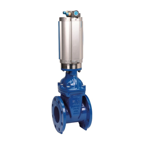
AVK 54 Series Instruction manual

SERIES 54 METAL SEATED GATE VALVES
INSTALLATION, OPERATION & MAINTENANCE MANUAL
Instruction for use
Thank you for selecting an AVK product. With correct use, it will give long and reliable service. This manual
has been prepared to assist you install, operate and maintain the valve to the maximum efficiency. For ease of
reference, it has been divided into sections covering all aspects of use, and it is in the users best interests to
read it and ensure that it is fully understood.
Health and Safety
It is always recommended that wherever work is being carried out on a valve that the valve is fully
depressurised prior to carrying it out, and for the convenience draining of the line may be beneficial.
It is essential that the user of the valve is aware of the weight of the components and/or assembles that must
be handled and manipulated during installation and maintenance. It is the users responsibility to ensure that
safe working practices are followed at all times.
Whenever AVK products are installed, operated, or maintained, it is essential that the staff that undertake
these operations be adequately trained. The hazards of pressurised liquids and gases can be severe, and it
is the responsibility of the users to ensure that trained, competent staff undertake these duties. This manual
has been designed to assist, but it can never fully replace quality training in the workplace. AVK technical staff
will always be available to answer any questions relating to specific problems that may not be covered by this
manual.
AVK products are designed and manufactured to be fit for purpose, and to a high and reliable standard. This
provides a safe product with minimum risk to health when used correctly for the purpose for which it was
designed. However, this assumes that the equipment is used and maintained in accordance with the manual,
and the user is advised to study this manual, and to make it available to all staff that may need to refer to it.
AVK cannot be held responsible for any incidents arising from incorrect installation, operation or maintenance.
The responsibility for this must rest wholly with the user.
AVK Valves Pty Ltd - 559A Grand Junction Road, Wingfield, SA 5013, Australia - Tel: +61 8 8368 0900 - Email: [email protected] - www.avkvalves.com.au Version number 2
COPYRIGHT©AVK GROUP A/S 2017

SERIES 54 METAL SEATED GATE VALVES
INSTALLATION, OPERATION & MAINTENANCE MANUAL
1. Introduction
AVK series 54 gate valves are available in DN750, DN800, DN900, DN1000 and DN1200. The valve has a full and straight bore
corresponding to the nominal diameter and can be installed independent of the flow direction. To keep the advantage of the full
and straight bore vertical installation is recommended, however, flow/pressure limitations outlined below should be observed.
The valves are 100% factory tested hydrostatically.
The valves have a standard gland flange according to ISO 5210. Various optional extras can be supplied factory fitted or in kit
form for retrofitting. See data sheet.
A complete by-pass system is factory fitted. The by-pass system secures an optimum installation due to slow filling and
emptying of the pipe line and passing of air.
IT IS IMPORTANT TO STATE OPERATING TEMPERATURE, PRESSURE, MEDIUM AND OPERATING CONDITIONS WITH
ENQUIRIES/ORDERS, SO THE MOST SUITABLE VALVE WILL BE SUPPLIED FOR YOUR SPECIFIC PURPOSE.
AVK Valves Pty Ltd - 559A Grand Junction Road, Wingfield, SA 5013, Australia - Tel: +61 8 8368 0900 - Email: [email protected] - www.avkvalves.com.au Version number 2
COPYRIGHT©AVK GROUP A/S 2017
AVK Valves Pty Ltd - 559A Grand Junction Road, Wingfield, SA 5013, Australia - Tel: +61 8 8368 0900 - Email: [email protected] - www.avkvalves.com.au Version number 2
COPYRIGHT©AVK GROUP A/S 2017
Materials:
Castings (body, bonnet, stem cap, wedge, stuffing box,
handwheel and bypass bends)
Ductile Iron
Coating
DN700-900:
Fusion bonded epoxy (FBE)
DN1000-1200:
Two pack epoxy
Bolts, nuts and stem
Stainless Steel
Refer to individual datasheets for specific information

SERIES 54 METAL SEATED GATE VALVES
INSTALLATION, OPERATION & MAINTENANCE MANUAL
AVK Valves Pty Ltd - 559A Grand Junction Road, Wingfield, SA 5013, Australia - Tel: +61 8 8368 0900 - Email: [email protected] - www.avkvalves.com.au Version number 2
COPYRIGHT©AVK GROUP A/S 2017
Component list
1. Body
2. Bonnet
3. Wedge
4. Distance piece
5. Body seat ring
6. Wedge ring
7. S t e m
8. Stem nut
9. Body, bonnet, O-ring seal
10. Gland packing
11. Gla nd
12. Fasteners
13. Plug
14. Gasket

SERIES 54 METAL SEATED GATE VALVES
INSTALLATION, OPERATION & MAINTENANCE MANUAL
2. Installation
• When installing the gate valves, ensure that the seats and the flange faces are clean.
• When valves are provided with lifting lugs, plates or eye nuts, these must be used to lift the valve.
• To ensure adequate sealing it is important to select the correct type of gasket for the medium concerned, 2 gaskets with
the correct flange size must be used.
• Place valve between pipe flanges, and insert the bolts.
• Tighten bolts loosely.
• Tighten bolts in a diagonal sequence to ensure flanges are pulled parallel.
• Finally tighten bolts to correct torque levels as recommended in WSA 109.
Once the valve has been installed (Commissioning)
• Check that the valve still functions correctly by operating it for a minimum of five turns.
• Direct mounted electric actuator open and close positions are pre-set at the works, and should not need adjustment but
torque settings may need adjustment by a suitably qualified engineer.
• Pedestal mounted actuators must be set on site.
• Where pedestals are fitted with open/close indicators, attention must be made during connection to ensure that they
correctly reflect the position of the valve.
• Packed Glands are the traditional method of sealing stems from the line pressure and are extremely reliable over a long
period of time. However, they do require an initial adjustment during the commissioning period and for this reason we
cannot guarantee “no leakage” until the valve is installed and adjusted. See 4. Maintenance.
• Where a venting plug or valve is fitted, this should be used to remove the air from the valve. Alternatively, where this is not
provided, air can be removed by loosening the gland bolts.
• When all the air has been safely vented, the cap, valve or gland bolts must be re-tightened ensuring that any gaskets or
washers are correctly seated.
• If the valve is fitted with a jacking screw ensure that this is retracted after use and before attempting to close the valve.
• When the pipeline has been charged, inspect the valve for any leaks and adjust as necessary in accordance with
maintenance instructions.
• All external debris and foreign matter should be cleaned off from the external surfaces of the valve.
• Any paint/coating which has been damaged during installation should be appropriately touched up.
AVK Valves Pty Ltd - 559A Grand Junction Road, Wingfield, SA 5013, Australia - Tel: +61 8 8368 0900 - Email: [email protected] - www.avkvalves.com.au Version number 2
COPYRIGHT©AVK GROUP A/S 2017

SERIES 54 METAL SEATED GATE VALVES
INSTALLATION, OPERATION & MAINTENANCE MANUAL
2.1. Exchange/retrofit a by-pass System
IMPORTANT! Before mounting a by-pass system:
1. The main valve must not be under pressure.
2. The medium must be below the level of the by-pass flanges on the side of the valve.
Preparation of the main valve.
Clean the flanges of the valve carefully to remove dirt and impurities.
Preparation of the main valve
Clean the flanges of the valve carefully to remove dirt and impurities.
Preparation of the by-pass system
Screw the stud bolts into the two cast iron bends and fit the bends to the by-pass valve together with the mating gaskets (see
drawing).
Fasten the nuts loosely to ensure that the bends can move freely in relation to the valve.
Mounting
Mount the by-pass system on the main valve together with new gaskets and re-use the nuts and washers removed previously
for fastening.
Tighten all nuts with 100 Nm. The by-pass system is now ready for use.
AVK Valves Pty Ltd - 559A Grand Junction Road, Wingfield, SA 5013, Australia - Tel: +61 8 8368 0900 - Email: [email protected] - www.avkvalves.com.au Version number 2
COPYRIGHT©AVK GROUP A/S 2017
SERIES 54 METAL SEATED GATE VALVES
INSTALLATION, OPERATION & MAINTENANCE MANUAL
3. Operation
The series 54 gate valves are suitable for use with clean water or neutral liquids up to 70°C; minimum liquid temperature must
be above freezing. Insulation is essential for use with low external temperatures.
The valves can be operated manually either by ring key and bar to tee key, handwheel, gearbox or electric actuation. Direction
of closing is on the ISO Mounting Gland Flange and the Gland Flange of a by-pass valve if fitted.
Note: These valves are not designed for “end of line” services. In the event of a valve being mounted on the end of a pipeline,
we strongly advise the use of blanking flange or plug.
3.1. Right-hand closing valves
3.1.1. Closing
During manual operation the valve is closed by turning the handwheel clockwise until the valve is completely closed, however
only up to max. operating torque (see table).
For valves supplied with gears, the handwheels are also turned clockwise. It is IMPORTANT that the interchange of the gear is
taken into consideration, so that the valve is not operated at a higher torque than max. operating torque (see table).
When closing valves with actuators, adjust the actuator so that the output shaft moves clockwise, and adjust the on/off torque
switch so that the valve is not operated at a higher torque than the max. operating torque (see table).
3.1.2. Opening
The valves are opened by turning the handwheel, gear or actuator anti-clockwise until the valve is completed open. This is
recognised by a powerful (and sudden) stop.
3.2. Left-hand closing valves
3.2.1. Closing
During manual operation the valve is closed by turning the handwheel anti-clockwise until the valve is completely close,
however only up to max. operating torque (see table).
For valves supplied with gears, the handwheels are turned anti-clockwise. It is IMPORTANT that the interchange of the gear is
taken into consideration, so that the valve is not operated at a higher torque than the max. operating torque (see table).
When closing valves with actuators, adjust the actuator so that the output shaft moves clockwise, and adjust the of/off torque
switch so that the valve is not operated at a higher torque than the max. operating torque (see table).
3.2.2. Opening
The valves are opened by turning the handwheel, gear or actuator clockwise until the valve is completely open. This is
recognised by a powerful (and sudden) stop.
AVK Valves Pty Ltd - 559A Grand Junction Road, Wingfield, SA 5013, Australia - Tel: +61 8 8368 0900 - Email: [email protected] - www.avkvalves.com.au Version number 2
COPYRIGHT©AVK GROUP A/S 2017
Torque Differential
DN Number 16 Bar 10 Bar 5 Bar
of Turns Nm Nm Nm
750 70 2466 1600 795
800 70 2466 1600 795
900 78 3260 2051 1043
1000 86 4108 2581 1308
1200 103 6561 4114 2075

SERIES 54 METAL SEATED GATE VALVES
INSTALLATION, OPERATION & MAINTENANCE MANUAL
4. Maintenance
To improve the life of the Series 54 Gate Valve and ensure satisfactory working at all times the following procedures should be
carried out at regular intervals throughout the life span of the product (every 6 months).
Although some procedures can be carried out with the valve under pressure, it is strongly recommended that there is no
pressure in the pipeline whenever possible.
• The stuffing box should be checked to conclude that there is no leakage from the packing.
An additional strand might be required after a period of service and occasionally repacking may be needed.
• Care should be taken to ensure the gland is tightened up evenly to prevent binding of the spindle, and should be tightened
up just enough to prevent leakage.
• If the valve has been left standing un-operated for lengthy periods and conditions allow, monthly or more frequent
operation of the screw throughout the length of its travel should be carried out. Failing this, at least operation through part
of the travel should be effected if at all possible.
• The bolts on the valve should be checked for tightness, after long periods of operation, where vibration is experienced.
• Visual checks of coating for any signs of damage or corrosion.
Packed Gland (Applies to all sizes)
Packed Glands are the traditional method of sealing stems from the line pressure and are extremely reliable over a long
period of time. However, they do require an initial adjustment during the commissioning period and for this reason we cannot
guarantee “no leakage” until the valve is installed and adjusted.
Adjustment is a simple matter of alternately tightening the gland nuts by a small amount until any weeping creases, this can
be safely carried out whilst under pressure. If the gland is already down and further adjustment is not available or does not
stop the leak, then the gland will need re-packing. If this is necessary, the pressure in the pipeline should be shut off at another
point, and the line drained.
To repack the valve, complete the following:
• Undo the gland nuts and then remove the gland and the packing.
• Lubricate the spindle with WRc Approved Grease.
• Repack the gland using the correct size and type of packing and ensure that there is a snug fit between the spindle and
the stuffing box wall, and that all joints are staggered by 120 degrees.
• Secure the gland but do not tighten the nuts more than necessary to prevent leakage.
Recommended Spare Parts
The use of interior materials or parts in a valve can have serious consequences. It is AVK policy therefore, to use only materials
of the highest quality, manufactured to our own designs and thoroughly checked and tested in accordance with our internal
Quality Assurance system that is approved to ISO 9001:2000. It is absolutely essential therefore, that in order to guarantee the
highest level of safety and performance, only genuine AVK spare parts are used. AVK can accept no responsibility whatsoever
for the fitting and subsequent failure of any non-AVK or non-approved parts.
AVK recommend that these spare parts are purchased when ordering series 54 Gate Valve
• Full set of Gaskets and Seals
• Gland Packing
• Grease for stem
• Touch up Paint
AVK Valves Pty Ltd - 559A Grand Junction Road, Wingfield, SA 5013, Australia - Tel: +61 8 8368 0900 - Email: [email protected] - www.avkvalves.com.au Version number 2
COPYRIGHT©AVK GROUP A/S 2017
Table of contents
Other AVK Control Unit manuals

AVK
AVK 816 Series Manual

AVK
AVK 764 Series User manual

AVK
AVK ACMO 879 Series Instruction manual

AVK
AVK 41 Series User manual

AVK
AVK 41 Series Instruction manual

AVK
AVK 145 Series User manual

AVK
AVK ACMO 879 Series Instruction manual

AVK
AVK 820 SERIES Installation and operating instructions

AVK
AVK 756 Series Instruction Manual

AVK
AVK 854 series User manual