AVK 41 Series Instruction manual

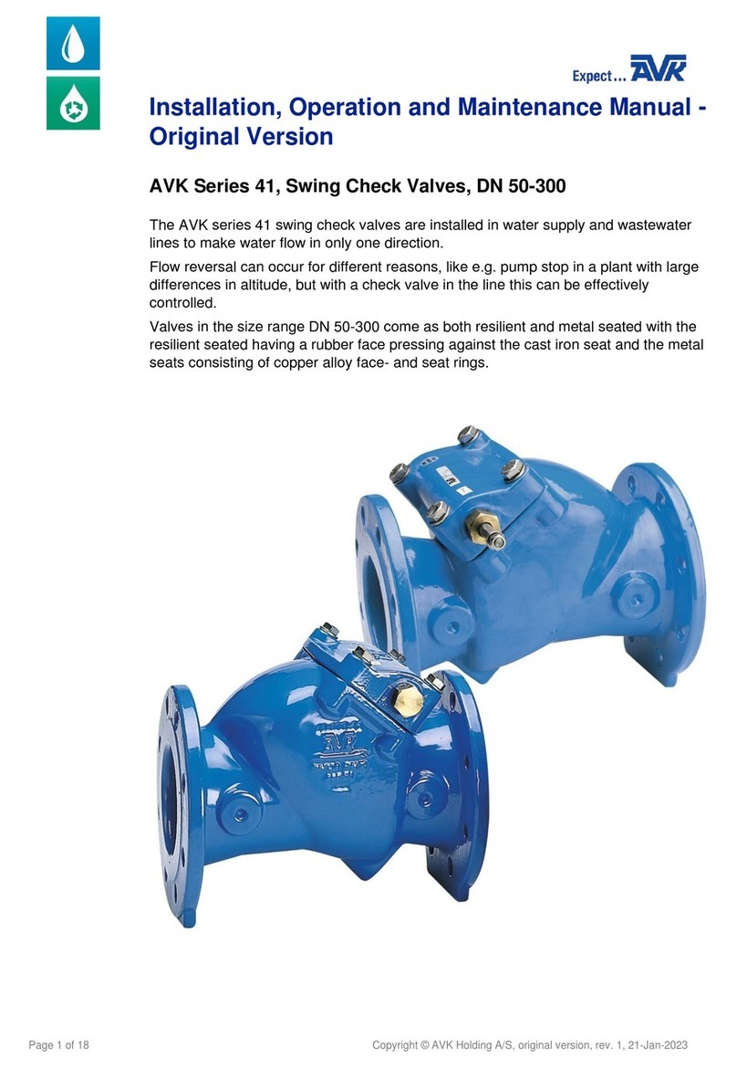
AVK SERIES 41 CHECK VALVE
INSTALLATION, OPERATION & MAINTENANCE MANUAL
Instruction for use
Thank you for selecting an AVK product. With correct use, the product is guaranteed to deliver a long and
reliable service. This manual has been prepared to assist you with the installation, operation and maintenance
of the valve to the maximum efficiency. For ease of reference, it has been divided into sections covering all
aspects of use, and it is in the users best interests to read it and ensure that it is fully understood.
Health and Safety
It is always recommended that wherever work is being carried out on a valve that the valve is fully
depressurised prior to carrying it out, and for the convenience draining of the line may be beneficial.
It is essential that the user of the valve is aware of the weight of the components and/or assembles that must
be handled and manipulated during installation and maintenance. It is the users responsibility to ensure that
safe working practices are followed at all times.
Whenever AVK products are installed, operated, or maintained, it is essential that the staff that undertake
these operations be adequately trained. The hazards of pressurised liquids and gases can be severe, and it
is the responsibility of the users to ensure that trained, competent staff undertake these duties. This manual
has been designed to assist, but it can never fully replace quality training in the workplace. AVK technical staff
will always be available to answer any questions relating to specific problems that may not be covered by this
manual.
AVK products are designed and manufactured to be fit for purpose, and to a high and reliable standard. This
provides a safe product with minimum risk to health when used correctly for the purpose for which it was
designed. However, this assumes that the equipment is used and maintained in accordance with the manual,
and the user is advised to study this manual, and to make it available to all staff that may need to refer to it.
AVK cannot be held responsible for any incidents arising from incorrect installation, operation or maintenance.
The responsibility for this must rest wholly with the user.
AVK Valves Pty Ltd, 559A Grand Junction Road, Wingfield, SA 5013, Australia - T: +61 8 8368 0900 - E: [email protected] - W: www.avkcivil.com.au Version number 3
COPYRIGHT©AVK GROUP A/S 2017 pp. 1 of 13
AVK SERIES 41 CHECK VALVE
INSTALLATION, OPERATION & MAINTENANCE MANUAL
Storage
• The valve should not come into contact with any contaminative substances prior to installation
• Valve end protectors (if supplied) should not be removed unless necessary for inspection or installation.
• Protection against weather should be provided. Ideally, valves should be kept indoors with the actual valve temperature
always higher than the dew point, particularly for valves fitted with actuators.
• If outdoor storage is unavoidable the valves should then be supported off the ground and protected by a weatherproof cover,
from dust-laden damp or saline conditions and at an ambient temperature.
• If long term storage is envisaged, then it may be considered prudent to have a AVK engineer inspect the valve prior to
installation.
Handling
A basic consideration in handling protected valves should be to avoid damaging the coating protection and valves should never
be thrown or dropped. Valves whose size requires handling by crane or lift truck should be slung or rigged carefully to avoid
damage to exposed valve parts.
Handwheels, bypass, actuators and gearboxes in particular, should not be used as lifting or rigging points for valves.
AVK Valves Pty Ltd, 559A Grand Junction Road, Wingfield, SA 5013, Australia - T: +61 8 8368 0900 - E: [email protected] - W: www.avkcivil.com.au Version number 3
COPYRIGHT©AVK GROUP A/S 2017 pp. 1 of 13
AVK Valves Pty Ltd, 559A Grand Junction Road, Wingfield, SA 5013, Australia - T: +61 8 8368 0900 - E: [email protected] - W: www.avkcivil.com.au Version number 3
COPYRIGHT©AVK GROUP A/S 2017 pp. 2 of 13

AVK SERIES 41 CHECK VALVE
INSTALLATION, OPERATION & MAINTENANCE MANUAL
1. Introduction
The AVK series 41 Swing Check Valves are designed for horizontal or vertical flow (not suitable for down-flow applications). The
design permits full bore flow and enables correct alignment of the resilient seated disc to the body seating surface. The valve
comes equipped with a bolted bonnet which can be removed while the valve is in the line.
Materials:
Body and bonnet
Ductile Iron to AS 1831
Coating
Electrostatically applied epoxy resin to AS 4158 - Internally
and externally
Shaft
Stainless Steel
Bonnet gasket
EPDM rubber
Bushing
Copper alloy AS/NZS 1567
Hexagon bolt, washer and pin
Stainless Steel
Resilient seated disc
EPDM rubber with a steel insert
Hinge
DN 80 - 200: Stainless steel
DN 250 - 300: Ductile Iron to AS 1831
Accessory kit:
Weight, hinge lever and weight
Ductile Iron to AS 1831
Cam
Stainless Steel
AVK Valves Pty Ltd, 559A Grand Junction Road, Wingfield, SA 5013, Australia - T: +61 8 8368 0900 - E: [email protected] - W: www.avkcivil.com.au Version number 3
COPYRIGHT©AVK GROUP A/S 2017 pp. 3 of 13

AVK SERIES 41 CHECK VALVE
INSTALLATION, OPERATION & MAINTENANCE MANUAL
Component list
1. Body
2. Bushing closed
3. Bonnet
4. Hexagon bolt
5. Washer
6. Bushing open
7. Lever
8. Nut
9. Washer
10. Weight
11. Grub screw
12. O-ring
13. O-ring
14. O-ring
15. Shaft
16. Bonnet gasket
17. Tab washer
18. Nut
19. Washer
20. Bushing
21. Hinge
22. Rubber disc
23. Hexagon bolt
24. Shaft protector
25. Connector
26. Key
27. Retaining washer
28. Spacer
H
L
Dt Dh D
ds
1 2 3 4567
8
9
10
11
18 19 20 21 22
17
12 13 14 15
16
25 26 27 28
24
DN80, 100, 150 and 200 DN250-300
Lever and weight as optional extras 23
AVK Valves Pty Ltd, 559A Grand Junction Road, Wingfield, SA 5013, Australia - T: +61 8 8368 0900 - E: [email protected] - W: www.avkcivil.com.au Version number 3
COPYRIGHT©AVK GROUP A/S 2017 pp. 4 of 13

AVK SERIES 41 CHECK VALVE
INSTALLATION, OPERATION & MAINTENANCE MANUAL
2. Installation
a) When installing the check valves, ensure that the seats and the flange faces are clean.
b) When valves are provided with lifting lugs, plates or eye nuts, these must be used to lift the valve.
c) To ensure adequate sealing it is important to select the correct type of gasket for the medium concerned, gaskets with the
correct flange size must be used.
d) Place valve between pipe flanges, and insert the bolts.
e) Tighten bolts loosely.
f) Tighten bolts in a diagonal sequence to ensure flanges are pulled parallel.
g) Finally tighten bolts to correct torque levels as recommended in WSA 109.
2.1. Bolts
2.1.1 Bolt size
The following table shows bolt size you should use for which valve dimensions.
AS 2129 AS 2129
Table B5 Table E Table F
DN Bolts Quantity Bolts Quantity Bolts Quantity
50 M16 4 M16 4 M16 4
80 M16 4 M16 4 M16 8
100 M16 4 M16 8 M16 8
150 M16 8 M20 8 M20 12
200 M16 8 M20 8 M20 12
225 M16 8 - - - -
250 M16 8 M20 12 M24 12
300 M20 12 M24 12 M24 16
375 M24 12 M24 12 M27 16
400 M24 12 M24 12 M27 20
AVK Valves Pty Ltd, 559A Grand Junction Road, Wingfield, SA 5013, Australia - T: +61 8 8368 0900 - E: [email protected] - W: www.avkcivil.com.au Version number 3
COPYRIGHT©AVK GROUP A/S 2017 pp. 5 of 13

AVK SERIES 41 CHECK VALVE
INSTALLATION, OPERATION & MAINTENANCE MANUAL
page 4
Top View
Direction of Flow
Fig. 2
Horizontal Mounting
Front View
page 5
Fig. 3
Vertical Mounting
Direction
of
Flow
Rear View Front View
Horizontal Mounting
Vertical Mounting
AVK Valves Pty Ltd, 559A Grand Junction Road, Wingfield, SA 5013, Australia - T: +61 8 8368 0900 - E: [email protected] - W: www.avkcivil.com.au Version number 3
COPYRIGHT©AVK GROUP A/S 2017 pp. 6 of 13

AVK SERIES 41 CHECK VALVE
INSTALLATION, OPERATION & MAINTENANCE MANUAL
Open Position
Closed Position
Closed Position
Open Position
page 6
Fig. 4
Optimal Leverage
Congurations
Horizontal Mounting
Vertical Mounting
Direction
of
Flow
Direction of Flow
Lever & weight positions
AVK Valves Pty Ltd, 559A Grand Junction Road, Wingfield, SA 5013, Australia - T: +61 8 8368 0900 - E: [email protected] - W: www.avkcivil.com.au Version number 3
COPYRIGHT©AVK GROUP A/S 2017 pp. 7 of 13

AVK SERIES 41 CHECK VALVE
INSTALLATION, OPERATION & MAINTENANCE MANUAL
3. Operation
Series 41 Swing Check Vlaves are suitable for use with wholesome (potable) water and low solids sewage up to 70oC. Minimum
liquid temperature must be above freezing.
Insulation is recommended for external temperatures from 0oC to -10oC. They can have a Lever & Weight option, Right Hand
as standard.
Design Constraints
Please consider the following points when selecting your valve:
Consideration should be given at the design stage where valves will be located to give access for operation, adjustment,
maintenance and repair.
If a valve is installed less than 5 pipe diameters upstream or downstream of any pump elbow or tee etc., it will experience very
high-localised velocities that are far in excess of the average velocity. This high velocity will result in excessive turbulence within
the valve and variations in performance may be experienced, therefore installation in this area should be avoided.
Valves must be provided with adequate support. Adjoining pipework must be supported to avoid the imposition of pipeline
strains on the body which may impair its performance.
Full flow is achieved with the disc positioned in the bonnet cavity, this occurs when velocity is greater than 1.5m/s. Velocities
above 4.5m/s can result in disc flutter reducing pump efficiencies and reducing the life of the valve.
For disc to seal a static pressure differential of a minimum of 70kpa is required.
AVK Valves Pty Ltd, 559A Grand Junction Road, Wingfield, SA 5013, Australia - T: +61 8 8368 0900 - E: [email protected] - W: www.avkcivil.com.au Version number 3
COPYRIGHT©AVK GROUP A/S 2017 pp. 8 of 13

AVK SERIES 41 CHECK VALVE
INSTALLATION, OPERATION & MAINTENANCE MANUAL
4. Maintenance
The valve is designed for use with minimum maintenance and requires no lubrication.
In the event of a spares replacement becoming necessary, the recommended procedure is as follows:
SAFETY PRECAUTIONS
a) Procedures must NOT be carried out whilst the valve is installed in a live main under pressure.
b) Ensure main will NOT be recharged before all work on the valve is completed.
4.1 Replacement of Brass Sealing Bushes with 'O' Ring Seals.
This can only be carried out when there is no pressure in the pipeline.
a) If fitted remove nut (8), washer (9) and lever (7) with weight (10).
NOTE: position of lever relative to body (1) for re-assembly.
b) Unscrew either bushing (2) or (6) and replace with new bushing complete with 'O' ring seals.
c) Repeat step b) with opposite side bushing.
d) Where necessary, refit lever (7), weight (10), washer (9) and nut (8).
Component list
1. Body
2. Bushing closed
3. Bonnet
4. Hexagon bolt
5. Washer
6. Bushing open
7. Lever
8. Nut
9. Washer
10. Weight
11. Grub screw
12. O-ring
13. O-ring
14. O-ring
15. Shaft
16. Bonnet gasket
17. Tab washer
18. Nut
19. Washer
20. Bushing
21. Hinge
22. Rubber disc
23. Hexagon bolt
24. Shaft protector
25. Connector
26. Key
27. Retaining washer
28. Spacer
H
L
Dt Dh D
ds
1 2 3 4567
8
9
10
11
18 19 20 21 22
17
12 13 14 15
16
25 26 27 28
24
DN80, 100, 150 and 200 DN250-300
Lever and weight as optional extras 23
AVK Valves Pty Ltd, 559A Grand Junction Road, Wingfield, SA 5013, Australia - T: +61 8 8368 0900 - E: [email protected] - W: www.avkcivil.com.au Version number 3
COPYRIGHT©AVK GROUP A/S 2017 pp. 9 of 13

AVK SERIES 41 CHECK VALVE
INSTALLATION, OPERATION & MAINTENANCE MANUAL
4.2 Replacement of Complete Bonnet Assembly (complete with Shaft, Hinge, Disc and Bushings).
This can only be carried out when there is no pressure in the pipeline.
a) Remove bonnet (3) by removing hexagon screws (4) and washers (5) and lift completed assembly from body (1).
(NOTE: Screws are different lengths.)
NOTE: If bushings only are to be replaced, follow steps in 4.1.
Check free movement of hinge prior to re-assembling of body.
a) Ensure that seat area in body is clean.
b) Fit hexagon screws (4) and washers (note different lengths) (5) through bonnet (1) and fit bonnet gasket (16) over screws
(4).
Fit bonnet (3) into body (1) with disc (23) facing correct way.
c) Tighten bonnet screws (4) in a diagonal sequence using torque wrench set at 25Nm to 30Nm. Reset the torque Wrench at
40Nm to 50Nm and re-tighten the screws following a circumferential sequence.
d) Slowly re-charge the main and check integrity of seals.
Component list
1. Body
2. Bushing closed
3. Bonnet
4. Hexagon bolt
5. Washer
6. Bushing open
7. Lever
8. Nut
9. Washer
10. Weight
11. Grub screw
12. O-ring
13. O-ring
14. O-ring
15. Shaft
16. Bonnet gasket
17. Tab washer
18. Nut
19. Washer
20. Bushing
21. Hinge
22. Rubber disc
23. Hexagon bolt
24. Shaft protector
25. Connector
26. Key
27. Retaining washer
28. Spacer
H
L
Dt Dh D
ds
1 2 3 4567
8
9
10
11
18 19 20 21 22
17
12 13 14 15
16
25 26 27 28
24
DN80, 100, 150 and 200 DN250-300
Lever and weight as optional extras 23
AVK Valves Pty Ltd, 559A Grand Junction Road, Wingfield, SA 5013, Australia - T: +61 8 8368 0900 - E: [email protected] - W: www.avkcivil.com.au Version number 3
COPYRIGHT©AVK GROUP A/S 2017 pp. 10 of 13

AVK SERIES 41 CHECK VALVE
INSTALLATION, OPERATION & MAINTENANCE MANUAL
4.3 Adding Lever & Counterweight to Series 41 Free End Shaft Valves
(DN50 up to DN300).
Safety Precaution : This can only be carried out, when there is no pressure in the pipeline.
Fitting of the parts:
a) Remove shaft protector (24) from free end of shaft (15).
b) Attached the lever (7) to the shaft (15) and secure with washer (9) and nut (8).
NOTE: The lever (7) must be aligned on the hexagon flats on the shaft (13) to ensure correct closure of the disc (22) and
clearance to a guard, if fitted. The alignment is also important with respect to the installation position of the valve, either
vertical or horizontal.
c) Mount the counterweight (10) onto the lever (7) and lock its position with the set screw (11). (DN250 & DN300 may have
more than one counterweight fitted). The weight can be moved on lever to adjust closing speeds. DO NOT adjust weight
while system is in operation.
d) Re-connect the flow and slowly fill the valve to check for correct operation.
Component list
1. Body
2. Bushing closed
3. Bonnet
4. Hexagon bolt
5. Washer
6. Bushing open
7. Lever
8. Nut
9. Washer
10. Weight
11. Grub screw
12. O-ring
13. O-ring
14. O-ring
15. Shaft
16. Bonnet gasket
17. Tab washer
18. Nut
19. Washer
20. Bushing
21. Hinge
22. Rubber disc
23. Hexagon bolt
24. Shaft protector
25. Connector
26. Key
27. Retaining washer
28. Spacer
H
L
Dt Dh D
ds
1 2 3 4 5 6 7
8
9
10
11
18 19 20 21 22
17
12 13 14 15
16
25 26 27 28
24
DN80, 100, 150 and 200 DN250-300
Lever and weight as optional extras 23
AVK Valves Pty Ltd, 559A Grand Junction Road, Wingfield, SA 5013, Australia - T: +61 8 8368 0900 - E: [email protected] - W: www.avkcivil.com.au Version number 3
COPYRIGHT©AVK GROUP A/S 2017 pp. 11 of 13

AVK SERIES 41 CHECK VALVE
INSTALLATION, OPERATION & MAINTENANCE MANUAL
4.4 Assembly of Cam Switch
a) Using M5 Tap clean out bracket bolt holes on side of valve body.
Ensure that the holes tapped are on the same side as the exposed
stem.
b) Using an Allen key attach the limit switch bracket to the valve body
with 2 x M5 screws.
c) Attach limit switch to bracket with 2 x M4 socket head bolts. Ensure
flat washer is behind bolt head and spring washer is behind nut.
d) With the valve in the fully closed position slide the cam over the
valve stem and rotate until switch is engaged. Pull the stem in and
out ensuring that it remains in contact with the switch at all times
Once positioned correctly apply a small amount of thread locking
compound (Loctite 277) to the grub screw and lock the cam into
position.
e) Check the switch operation ensuring that when the valve is closed
the switch remains engaged on the cam. If this does not occur
return to step d) and reposition the cam.
AVK Valves Pty Ltd, 559A Grand Junction Road, Wingfield, SA 5013, Australia - T: +61 8 8368 0900 - E: [email protected] - W: www.avkcivil.com.au Version number 3
COPYRIGHT©AVK GROUP A/S 2017 pp. 12 of 13

AVK SERIES 41 CHECK VALVE
INSTALLATION, OPERATION & MAINTENANCE MANUAL
4.5 Installation of Proximity Switch
a) If not already fitted, fit the standard mechanical switch mounting
bracket using two M5 Button Head screws to the side of the valve
that the switch will be mounted
b) Fit the proximity mounting bracket to the mechanical switch bracket
using the two M4 socket screws, nuts and washers.
Note: Ensure the screw, washer and bracket arrangement is
assembled correctly in the order of socket screw, flat washer,
proximity bracket, mechanical switch bracket, spring washer, nut.
With the grub screw inserted into the proximity cam mount the proximity
cam and grub assembly onto the shaft and positioning it centrally to
the aperture of the proximity bracket, lightly tighten the grub screw
to clamp the cam in a preliminary position.
d) Insert the proximity switch through the mounting bracket and fit the
lock nuts.
Adjust the proximity switch position in relation to the cam lobe and
set the sensing gap to 3mm.
Tighten lock nuts to secure the proximity switch in position.
Lock the M5 grub screw in the cam to secure the position and
check to ensure the cam does not contact with the proximity switch.
e) Fit the lever and weight assembly (if required) to the shaft and
secure with the locknut and washer. This completes the proximity
switch mounting.
3mm
AVK Valves Pty Ltd, 559A Grand Junction Road, Wingfield, SA 5013, Australia - T: +61 8 8368 0900 - E: [email protected] - W: www.avkcivil.com.au Version number 3
COPYRIGHT©AVK GROUP A/S 2017 pp. 13 of 13
Other manuals for 41 Series
4
This manual suits for next models
9
Table of contents
Other AVK Control Unit manuals

AVK
AVK 854 series User manual

AVK
AVK 41 Series User manual

AVK
AVK 641 Series User manual

AVK
AVK 869 Series User manual

AVK
AVK 816 Series Manual

AVK
AVK 02 Series User manual

AVK
AVK 715 Series User manual

AVK
AVK 57/46 Series Instruction manual

AVK
AVK ACMO 879 Series Instruction manual

AVK
AVK 145 Series User manual

AVK
AVK 41 Series User manual

AVK
AVK 764 Series User manual

AVK
AVK ACMO 879 Series Instruction manual

AVK
AVK 54 Series Instruction manual

AVK
AVK 820 SERIES Installation and operating instructions

AVK
AVK 879 Series Instruction manual

AVK
AVK 41 Series User manual

AVK
AVK 41 Series Troubleshooting guide

AVK
AVK 756 Series Instruction Manual