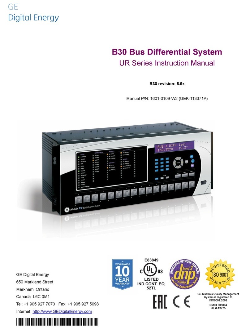
GE MM200 User manual

*1601-9034-A8*
MM200
Motor Management System
Low voltage motor protection and control
GE
Grid Solutions
LISTED
52TL
IND.CONT. EQ.
E83849
Instruction Manual
MM200 Revision: 1.2x
Manual P/N: 1601-9034-A8
Manual Order Code: GEK-113400G

© 2017 GE Multilin Incorporated. All rights reserved.
GE Multilin MM200 Motor Management System instruction manual for revision 1.2x.
MM200 Motor Management System, EnerVista, EnerVista Launchpad, and EnerVista
MM300/MM200 Setup are registered trademarks of GE Multilin Inc.
The contents of this manual are the property of GE Multilin Inc. This documentation is
furnished on license and may not be reproduced in whole or in part without the permission
of GE Multilin. The content of this manual is for informational use only and is subject to
change without notice.
Part number: 1601-9034-A8 (June 2017)
Storage
Store the unit indoors in a cool, dry place. If possible, store in the original packaging. Follow
the storage temperature range outlined in the Specifications.
To avoid deterioration of electrolytic capacitors, power up units that are stored in a de-
energized state once per year, for one hour continuously.
This product cannot be disposed of as unsorted municipal waste in the European
Union. For proper recycling return this product to your supplier or a designated
collection point. For more information go to www.recyclethis.info.

MM200 MOTOR MANAGEMENT SYSTEM – INSTRUCTION MANUAL TOC–I
Table of Contents
1.INTRODUCTION Overview .............................................................................................................................................. 1 - 1
Cautions and Warnings..........................................................................................................................1 - 2
Safety words and definitions ...............................................................................................................1 - 2
General Safety Precautions - MM200..............................................................................................1 - 2
For Further Assistance ............................................................................................................................1 - 3
Description of the MM200 Motor Management system.........................................................1 - 4
MM200 order codes .................................................................................................................................1 - 6
Example of an MM200 order code....................................................................................................1 - 6
Specifications..................................................................................................................................... 1 - 7
Protection specifications .......................................................................................................................1 - 7
User interface specifications ...............................................................................................................1 - 8
Control specifications..............................................................................................................................1 - 8
Inputs specifications ................................................................................................................................1 - 9
Outputs specifications ............................................................................................................................1 - 9
Power supply specifications ............................................................................................................. 1 - 10
Communications specifications ...................................................................................................... 1 - 10
Testing and certification ..................................................................................................................... 1 - 10
Physical specifications......................................................................................................................... 1 - 12
Environmental specifications ........................................................................................................... 1 - 12
2.INSTALLATION Mechanical installation ................................................................................................................. 2 - 1
Dimensions...................................................................................................................................................2 - 2
Product identification ..............................................................................................................................2 - 2
Mounting .......................................................................................................................................................2 - 3
Electrical installation ...................................................................................................................... 2 - 6
Thermistor connections ...................................................................................................................... 2 - 11
RS485 connections................................................................................................................................ 2 - 12
Protection................................................................................................................................................... 2 - 13
Phase current inputs.............................................................................................................................2 - 13
Input/output.............................................................................................................................................. 2 - 16
Type IO_C connections ........................................................................................................................2 - 16
Dielectric strength testing.................................................................................................................. 2 - 17
Starter types.....................................................................................................................................2 - 19
Full-voltage non-reversing starter ................................................................................................. 2 - 19
Full-voltage reversing starter ........................................................................................................... 2 - 20
Two-speed starter.................................................................................................................................. 2 - 22
General Maintenance...................................................................................................................2 - 24
In-service maintenance ...................................................................................................................... 2 - 24
Out-of-service maintenance............................................................................................................. 2 - 24
Unscheduled maintenance (system interruption) .................................................................. 2 - 24
3.CONTROL PANEL Basic control panel.......................................................................................................................... 3 - 2
Graphical control panel ................................................................................................................ 3 - 3
Introduction to the graphical control panel .................................................................................3 - 3
Graphical display.......................................................................................................................................3 - 3
Keypad............................................................................................................................................................3 - 5
Control keys .................................................................................................................................................3 - 7
Out-of-service maintenance................................................................................................................3 - 7
MM200 graphical display pages........................................................................................................3 - 8
Home display page...................................................................................................................................3 - 9
Default display............................................................................................................................................3 - 9

TOC–II MM200 MOTOR MANAGEMENT SYSTEM – INSTRUCTION MANUAL
Actual values pages...............................................................................................................................3 - 10
Status pages .............................................................................................................................................3 - 10
Setpoints pages.......................................................................................................................................3 - 11
Diagnostics pages ..................................................................................................................................3 - 12
Control page..............................................................................................................................................3 - 12
Popup windows .......................................................................................................................................3 - 13
MM200 programming techniques ..................................................................................................3 - 14
Enumeration setpoints.........................................................................................................................3 - 14
Numeric setpoints ..................................................................................................................................3 - 14
Alphanumeric setpoints.......................................................................................................................3 - 15
Date and time...........................................................................................................................................3 - 16
Security access........................................................................................................................................3 - 16
EnerVista MM200 Setup Software .........................................................................................3 - 17
Software requirements ........................................................................................................................3 - 17
Troubleshooting the USB driver .......................................................................................................3 - 17
Installing the EnerVista MM300/MM200 Setup software.....................................................3 - 20
Backing up settings................................................................................................................................3 - 24
Restoring settings ...................................................................................................................................3 - 24
Upgrading firmware ..............................................................................................................................3 - 25
Loading new relay firmware .............................................................................................................3 - 25
Upgrading the software.......................................................................................................................3 - 28
Uninstalling files and clearing data................................................................................................3 - 28
4.SETPOINTS Understanding setpoints...............................................................................................................4 - 1
Setting text abbreviations..................................................................................................................... 4 - 1
Configuration setpoints .................................................................................................................4 - 2
Motor setpoints.......................................................................................................................................... 4 - 2
Common motor setpoints..................................................................................................................... 4 - 2
Full-voltage non-reversing starter.................................................................................................... 4 - 4
Full-voltage reversing starter.............................................................................................................. 4 - 4
Two-speed starter .................................................................................................................................... 4 - 5
Current transformers .............................................................................................................................. 4 - 7
Inputs.............................................................................................................................................................. 4 - 8
Outputs .......................................................................................................................................................... 4 - 9
Communications setpoints .................................................................................................................. 4 - 9
System .........................................................................................................................................................4 - 11
System security.......................................................................................................................................4 - 11
System trouble.........................................................................................................................................4 - 11
LED indicators...........................................................................................................................................4 - 12
Counters Settings....................................................................................................................................4 - 13
Protection elements .....................................................................................................................4 - 14
Thermal protection.................................................................................................................................4 - 14
Hot/cold biasing ......................................................................................................................................4 - 14
Overload curve.........................................................................................................................................4 - 15
Cooling rate ...............................................................................................................................................4 - 18
Thermal protection reset.....................................................................................................................4 - 18
Thermal protection setpoints............................................................................................................4 - 19
Mechanical protection..........................................................................................................................4 - 20
Mechanical jam .......................................................................................................................................4 - 20
Undercurrent protection .....................................................................................................................4 - 20
Acceleration protection .......................................................................................................................4 - 21
Electrical protection...............................................................................................................................4 - 22
Current unbalance protection ..........................................................................................................4 - 22
Ground fault protection .......................................................................................................................4 - 22
Load increase alarm..............................................................................................................................4 - 23
Control elements............................................................................................................................4 - 24

MM200 MOTOR MANAGEMENT SYSTEM – INSTRUCTION MANUAL TOC–III
Auto/manual control ............................................................................................................................ 4 - 24
Stop/start control element................................................................................................................. 4 - 26
Power failure restart ............................................................................................................................. 4 - 27
5.DIAGNOSTICS Digital counters................................................................................................................................. 5 - 1
Learned data...................................................................................................................................... 5 - 2
Commands.......................................................................................................................................... 5 - 3
6.COMMUNICATION
S
Communications interfaces........................................................................................................ 6 - 1
A.APPENDIX A Change notes..................................................................................................................................... A - 1
Revision history..........................................................................................................................................A - 1
Warranty.............................................................................................................................................. A - 3
Repairs .................................................................................................................................................. A - 3

TOC–IV MM200 MOTOR MANAGEMENT SYSTEM – INSTRUCTION MANUAL

MM200 MOTOR MANAGEMENT SYSTEM – INSTRUCTION MANUAL 1–1
MM200 Motor Management System
Chapter 1: Introduction
GE
Grid Solutions
Introduction
Overview
The MM200 is a motor protection and control system designed specifically for low-voltage
motor applications. The MM200 provides the following key benefits.
• Protection, control, and communication options to suit low-voltage motor
applications.
• Small footprint designed specifically for IEC and NEMA MCC applications.
• DIN rail Mounting.
• Multiple communication protocols allows simple integration into monitoring and
control systems.
• Optional basic or graphical control panel interfaces provides local control and access
to system information.

1–2 MM200 MOTOR MANAGEMENT SYSTEM – INSTRUCTION MANUAL
OVERVIEW CHAPTER 1: INTRODUCTION
Cautions and Warnings
Before attempting to install or use the device, review all safety indicators in this document
to help prevent injury, equipment damage, or downtime.
Safety words and
definitions
The following symbols used in this document indicate the following conditions
DANGER: Indicates a hazardous situation which, if not avoided, will result in death or serious
injury.
IMPORTANT: Indicates a hazardous situation which, if not avoided, could result in death or serious
injury.
CAUTION: Indicates a hazardous situation which, if not avoided, could result in minor or
moderate injury.
NOTE
NOTE: Indicates practices not related to personal injury.
General Safety
Precautions - MM200
CAUTION: Failure to observe and follow the instructions provided in the equipment manual(s)
could cause irreversible damage to the equipment and could lead to property damage,
personal injury and/or death.
Before attempting to use the equipment, it is important that all danger and caution
indicators are reviewed.
If the equipment is used in a manner not specified by the manufacturer or functions
abnormally, proceed with caution. Otherwise, the protection provided by the
equipment may be impaired and can result in Impaired operation and injury.
Caution: Hazardous voltages can cause shock, burns or death.
Installation/service personnel must be familiar with general device test practices,
electrical awareness and safety precautions must be followed.
Before performing visual inspections, tests, or periodic maintenance on this device or
associated circuits, isolate or disconnect all hazardous live circuits and sources of
electric power.
Failure to shut equipment off prior to removing the power connections could expose
you to dangerous voltages causing injury or death.
All recommended equipment that should be grounded and must have a reliable and
un-compromised grounding path for safety purposes, protection against
electromagnetic interference and proper device operation.
Equipment grounds should be bonded together and connected to the facility’s main
ground system for primary power.
Keep all ground leads as short as possible.

CHAPTER 1: INTRODUCTION OVERVIEW
MM200 MOTOR MANAGEMENT SYSTEM – INSTRUCTION MANUAL 1–3
At all times, equipment ground terminal must be grounded during device operation
and service.
In addition to the safety precautions mentioned all electrical connections made must
respect the applicable local jurisdiction electrical code.
Before working on CTs, they must be short-circuited.
For Further Assistance
For product support, contact the information and call center as follows:
GE Grid Solutions
650 Markland Street
Markham, Ontario
Canada L6C 0M1
Worldwide telephone: +1 905 927 7070
Europe/Middle East/Africa telephone: +34 94 485 88 54
North America toll-free: 1 800 547 8629
Fax: +1 905 927 5098
Worldwide e-mail: multilin.tech@ge.com
Website: http://www.gegridsolutions.com/multilin

1–4 MM200 MOTOR MANAGEMENT SYSTEM – INSTRUCTION MANUAL
OVERVIEW CHAPTER 1: INTRODUCTION
Description of the MM200 Motor Management system
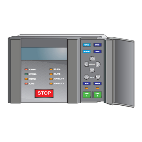
The MM200 can be equipped with either of two control panels, or with no control panel.
• Basic control panel: includes pushbuttons for Stop, Start A, Start B, Auto, Manual, and
Reset, and 12 LED status indicators.
• Graphical control panel: includes a 3.5-inch 320 by 240 pixel backlit color LCD screen,
14 pushbuttons and 10 LED indicators, which provide access to actual values, trip and
alarm lists, event records, and setting configuration. A USB port is provided for laptop
computer connection.
The MM200 includes the following input/output capabilities:
• 2 Form A relays, 1 Form C relay
• 7 contact inputs LO power supply; 6 contact inputs HI power supply.
The thermal model uses a standard overload curve with multiplier, and incorporates hot/
cold compensation and exponential cooling.
A single-line diagram for the MM200 is shown below.
Figure 1-1: Single line diagram
RS485 - Modbus RTU
Profibus/DeviceNet
52
METERING
A
51R 49 37 46
50G
MOTOR
LOAD
Temperature
Thermistor
Phase CT 3
Ground CT 1
Power Fuse
BUS
MM200
MOTOR MANAGEMENT SYSTEM
Contactor
888739A3.CDR
LO: 7 inputs and 3 outputs
HI: 6 inputs and 3 outputs
LO: 24 V DC
HI: 120 to 240 V AC

CHAPTER 1: INTRODUCTION OVERVIEW
MM200 MOTOR MANAGEMENT SYSTEM – INSTRUCTION MANUAL 1–5
Table 1-1: MM200 protection functions
Figure 1-2: MM200 feature overview
ANSI device Description
37 Undercurrent
46 Current unbalance
49 Thermal overload
50G Ground instantaneous overcurrent
51R Locked/stalled rotor, mechanical jam
Graphical display
• Large metering values
• Wide viewing angle
Entry Level Control Panel
• Control keys
• LED Indication
Soft key navigation
• Graphical module control
Front port access
•USB for laptop connection
Integrated functionality
• Protection, metering, control
LED indication
• Motor status
• Alarm indication
• System status
• Communication status
• Additional user LEDs
Ease of use
• Graphical interface
• Self-description
Mounting options
• DIN Rail
• Through door
888755A1.CDR
Front panel control
• Integrated device control
• Dedicated control keys

1–6 MM200 MOTOR MANAGEMENT SYSTEM – INSTRUCTION MANUAL
OVERVIEW CHAPTER 1: INTRODUCTION
MM200 order codes
The information to specify an MM200 relay is provided in the following order code figure.
Figure 1-3: MM200 order codes
NOTE
NOTE: Harsh Environment Coating is a standard feature on all MM200 units.
Example of an MM200 order code
MM200-BXL1S: MM200 with basic control panel, 24 V DC power supply, RS485 Modbus
RTU communications, three-phase current, thermal overload, undercurrent, Devicenet
communications, protection option.
888702A3.PDF
Base
MM200 * X * * * Description (7 inputs, 2 Form A, 1 Form C, 3 CT, CBCT,
Thermistor)
MM200 | | | | MM200 Motor Management System
Control panel X | | | No Control Panel
B | | | Basic Control Panel, no USB
G | | | Graphical control panel with USB
Power supply H |
||
|6 AC Digital inputs 65 to 300 V AC, 3 Outputs (2 form A, 1
form C), 3CT, CBCT, thermistor
L|
||
|7 DC digital inputs 24 V DC, 3 Outputs (2 form A, 1 form C),
3CT, CBCT, thermistor
Communications 1 | RS485 Modbus RTU plus DeviceNet Slave
2 | RS485 plus Profibus DP slave
S | Standard Communications: RS485 Modbus RTU
Protection S Standard Protection and Control

CHAPTER 1: INTRODUCTION SPECIFICATIONS
MM200 MOTOR MANAGEMENT SYSTEM – INSTRUCTION MANUAL 1–7
Specifications
NOTE
NOTE: Specifications are subject to change without notice.
Protection specifications
ACCELERATION TIMER
Pickup:......................................................................Iav > Icutoff
Dropout: ..................................................................Iav < Ipu or timer expired
Time delay: ............................................................ 0.5 to 250.0 seconds in steps of 0.1
Timing accuracy:................................................ ±500 ms or 1.5% of total time
Elements: ................................................................ trip and alarm
CURRENT UNBALANCE
Range: ...................................................................... 4 to 40% in steps of 1%
Accuracy:................................................................ ±2%
Time delay: ............................................................ 1 to 60 seconds in steps of 1 s
Timing accuracy:................................................ ±500 ms
Elements: ................................................................ trip and alarm
GROUND FAULT (CBCT)
Pickup level:........................................................... 0.5 to 15.0 A in steps of 0.1 A
Trip time delay on start:................................... 0 to 10 s in steps of 0.1 s
Trip time delay on run: ..................................... 0 to 5 s in steps of 0.1 s
Alarm time delay on start/run:..................... 0 to 60 s in steps of 1 s
Timing accuracy:................................................ ±100 ms or ±0.5% of total time
Elements: ................................................................ trip and alarm
LOAD INCREASE
Pickup level:........................................................... 50 to 150% of FLA in steps of 1%
Timing accuracy:................................................ ±500 ms
Elements: ................................................................ Alarm
MECHANICAL JAM
Pickup level:........................................................... 1.01 to 4.50 × FLA in steps of 0.01
Time delay: ............................................................ 0.1 to 30.0 seconds in steps of 0.1
Timing accuracy:................................................ ±500 ms
Elements: ................................................................ trip
CALCULATION METHOD
If IAV ≥IFLA: ( [IM- IAV] /IAV ) x 100%
If IAV ≤IFLA: ( [IM- IAV] /IFLA ) x 100%
Where:
IAV = average phase current
IM= current in a phase with maximum deviation from IAV
IFLA = MOTOR FULL LOAD AMPS setpoint

1–8 MM200 MOTOR MANAGEMENT SYSTEM – INSTRUCTION MANUAL
SPECIFICATIONS CHAPTER 1: INTRODUCTION
THERMAL MODEL
Standard curve time multiplier: ................... 1 to 15 in steps of 1
Thermal overload pickup:............................... 1.01 to 1.25 in steps of 0.01 x FLA
Motor full load current (FLA): ......................... 0.5 to 1000 A in steps of 0.1
Motor rated voltage: ......................................... 100 to 690 V AC
Curve biasing:....................................................... hot/cold ratio exponential running and stopped cooling
rates
Update rate:.......................................................... 3 cycles
Hot/cold safe stall ratio: .................................. 1 to 100% in steps of 1%
Timing accuracy:................................................ ±200 ms or ±2% of total time (based on measured value)
Elements:................................................................ trip
THERMISTOR
Sensor types:........................................................ PTC (RHOT = 100 to 30 kohms); NTC (RHOT = 100 to 30 kohms)
Timing accuracy:................................................ ±500 ms
Elements:................................................................ Trip and alarm
UNDERCURRENT
Pickup level:........................................................... 1 to 100% of FLA in steps of 1
Time delay:............................................................ 1 to 60 seconds in steps of 1
Timing accuracy:................................................ ±500 ms
Elements:................................................................ Trip and alarm
POWER FAILURE RESTART
Type: ......................................................................... Digital input
Power failure time:............................................. 0 to 30 seconds in steps of 1
Restart time delay:............................................. 0 to 300 seconds in steps of 1
UV detection time accuracy: ........................ ±100 ms or ±5%
User interface specifications
GRAPHICAL DISPLAY PANEL AND HAND HELD DISPLAY
Size: ........................................................................... width 153mm, height 102mm, depth 35mm
LCD:........................................................................... 3.5-inch color, 320 by 240 pixels
LED Indicators:..................................................... 10 LEDs
Pushbuttons:......................................................... Start A, Start B, Stop, plus 11 LCD screen display control keys
Ports:......................................................................... USB 2.0 port for laptop computer connection
Cable - GCP to Base Unit:................................ Shielded RJ45; Maximum length 3' (1m) @ minimum AWG: 26
BASIC CONTROL PANEL
Size: ........................................................................... BCP: width 75mm, height 75mm, depth 31mm
LED Indicators:..................................................... 12 LEDs
Pushbuttons:......................................................... Start A, Start B, Stop, Reset, Auto, Manual
Cable - BCP to Base Unit:................................ Shielded RJ45; Maximum length 6.6' (2m) @ minimum
AWG: 26
Control specifications
POWER FAILURE RESTART
Type: ......................................................................... Digital input
Power failure time:............................................. 0 to 30 seconds in steps of 1
Restart time delay:............................................. 0 to 300 seconds in steps of 1
UV detection time accuracy: ........................ ±100 ms or ±5%

CHAPTER 1: INTRODUCTION SPECIFICATIONS
MM200 MOTOR MANAGEMENT SYSTEM – INSTRUCTION MANUAL 1–9
Inputs specifications
DIGITAL INPUTS (LO)
Fixed pickup: ......................................................... 24 V DC
Continuous current draw:............................... 4 mA
Type: ......................................................................... opto-isolated inputs
External switch: ................................................... wet contact
Maximum input voltage:.................................. 36 V DC
DIGITAL INPUTS (HI)
Nominal voltage:................................................. 120 V AC to 240 V AC
Recognition time:................................................ 2 cycles
Continuous current draw:............................... 4 mA @120 V AC; 8 mA @ 240 V AC
Type: ......................................................................... opto-isolated inputs
External switch: ................................................... wet contact
Voltage range: ...................................................... 65 V AC to 300 V AC
GROUND CURRENT INPUT (50:0.025)
CT primary: ............................................................ 0.5 to 15.0 A
Nominal frequency:........................................... 50 or 60 Hz
Accuracy (CBCT): ................................................. ±0.1 A (0.5 to 3.99 A)
±0.2 A (4.0 A to 15 A)
PHASE CURRENT INPUTS
Range: ...................................................................... 0.07 to 40 A (8 × CT), direct connection up to 5 A FLA
Input type:.............................................................. combined 1 A / 5 A
Frequency: ............................................................. 50 or 60 Hz
Accuracy:................................................................ ExtCT: ±2% of reading or ±1% of 8× CTPrimary, whichever is
greater
Direct: 2% of reading or ±0.1 A, whichever is greater
Withstand (at 5A nominal):............................. 0.2 s at 100 × rated current
1.0 s at 50 × rated current
2.0 s at 40 × rated current
continuous at 3 × rated current
maximum 100 A peak
Short Circuit:.......................................................... 5000 A @ 240 V AC direct connect
100000 A @ 600 VAC with accessory external CT
THERMISTOR INPUTS
Sensor type: .......................................................... Positive temperature coefficient PTC (RHOT = 100 to
30000 ohms), negative temperature coefficient NTC (RHOT =
100 to 30000 ohms)
Accuracy:................................................................ ±6% of reading or ±100 ohms, whichever is greater
Outputs specifications
OUTPUT RELAYS
Configuration:....................................................... electromechanical 2 x Form-A and 1 x Form-C
Contact material: ................................................ silver-alloy
Operate time:........................................................ 10 ms
Minimum contact load: .................................... 10 mA at 5 V DC
Maximum switching rate: ............................... 300 operations per minute (no load), 30 operations per
minute (load)
Mechanical life:.................................................... 10 000 000 operations
Continuous current:........................................... 5 A at 60°C
Make and carry for 0.2s:.................................. 30 A per ANSI C37.90 (not UL rated)

1–10 MM200 MOTOR MANAGEMENT SYSTEM – INSTRUCTION MANUAL
SPECIFICATIONS CHAPTER 1: INTRODUCTION
OUTPUT RELAY BREAK CAPACITY (FORM-A RELAY)
AC resistive, 120 V AC: ...................................... 5 A
AC resistive, 250 V AC: ...................................... 5 A
AC inductive, PF = 0.4:....................................... 240 VA pilot duty
DC resistive, 30 V DC:........................................ 5 A
OUTPUT RELAY BREAK CAPACITY (FORM-C RELAY)
AC resistive, 120 V AC: ...................................... 5 A normally-open, 5 A normally-closed
AC resistive, 240 V AC: ...................................... 5 A normally-open, 5 A normally-closed
AC inductive, PF = 0.4:....................................... 240 VA pilot duty
DC resistive, 30 V DC:........................................ 5 A
Power supply specifications
POWER SUPPLY (LO RANGE)
Nominal:.................................................................. 24 V DC
Range:...................................................................... 18 to 36 V DC
Power Consumption:......................................... 10 W typical
POWER SUPPLY (HI RANGE)
Nominal:.................................................................. 120 to 240 V AC
Range:...................................................................... 60 to 300 V AC (50 and 60 Hz)
Power consumption: ......................................... 10 W typical
Voltage withstand: ............................................. 2 × highest nominal voltage for 10 ms
Communications specifications
DEVICENET (COPPER)
Modes: ..................................................................... slave (125, 250, and 500 kbps)
Connector: ............................................................. 5-pin terminal
Current Draw:....................................................... 80 mA at 24 VDC
PROFIBUS (COPPER)
Modes: ..................................................................... DP V0 slave, up to 1.5 Mbps
Connector: ............................................................. 5-pin terminal
RS485 PORT
Port:........................................................................... opto-isolated
Baud rates: ............................................................ up to 115 kbps
Protocol:.................................................................. Modbus RTU, half-duplex
Maximum distance:........................................... 1200 m
Isolation: ................................................................. 2 kV
Testing and certification
TYPE TESTS
Test Reference Standard Test Level
Dielectric voltage withstand 2.3KV
Impulse voltage withstand EN60255-5 5KV
Damped Oscillatory IEC61000-4-18IEC60255-22-1 2.5KV CM, 1KV DM
Electrostatic Discharge EN61000-4-2/IEC60255-22-2 Level 4
RF immunity EN61000-4-3/IEC60255-22-3 Level 3
Fast Transient Disturbance EN61000-4-4/IEC60255-22-4 Class A
Surge Immunity EN61000-4-5/IEC60255-22-5 Level 3
Conducted RF Immunity EN61000-4-6/IEC60255-22-6 Level 3

CHAPTER 1: INTRODUCTION SPECIFICATIONS
MM200 MOTOR MANAGEMENT SYSTEM – INSTRUCTION MANUAL 1–11
EAC
The EAC Technical Regulations (TR) for Machines and Equipment apply to the Customs
Union (CU) of the Russian Federation, Belarus, and Kazakhstan
Power Frequency Immunity EN61000-4-7/IEC60255-22-7 Class A
Voltage interruptionand Ripple DC IEC60255-11 15% ripple, 200ms interupts
Radiated & Conducted Emissions CISPR11 /CISPR22/ IEC60255-25 Class A
Sinusoidal Vibration IEC60255-21-1 Class 1
Shock & Bump IEC60255-21-2 Class 1
Siesmic IEC60255-21-3 Class 2
Power magnetic Immunity IEC61000-4-8 Level 5
Pulse Magnetic Immunity IEC61000-4-9 Level 4
Damped Magnetic Immunity IEC61000-4-10 Level 4
Voltage Dip & interruption IEC61000-4-11 0,40,70% dips,250/300cycle
interrupts
Damped Oscillatory IEC61000-4-12 2.5KV CM, 1KV DM
Voltage Ripple IEC61000-4-17 15% ripple
Ingress Protection IEC60529 IP20 (base unit) , IP54
(Control Panel)
Environmental (Cold) IEC60068-2-1 -25C 16 hrs
Environmental (Dry heat) IEC60068-2-2 70C 16hrs
Relative Humidity Cyclic IEC60068-2-30 6day variant 2
UL508 e83849 NKCR
Safety UL C22.2-14 e83849 NKCR7
UL1053 e83849 NKCR
CERTIFICATION
APPROVAL
Applicable Council Directive According to
Low voltage directive EN60255-5, EN60255-27
CE compliance EMC Directive EN60255-26 / EN50263
UL508
North America cULus UL1053
C22.2.No 14
EAC Machines and Equipment TR CU 010/2011
ISO: Manufactured under a registered
quality program ISO9001
Item Description
Country of origin Spain or Canada; see label on the unit
Date of manufacture See label on the side of the MM200 unit
Declaration of Conformity and/or Certificate of
Conformity
Available on request
TYPE TESTS
Test Reference Standard Test Level

1–12 MM200 MOTOR MANAGEMENT SYSTEM – INSTRUCTION MANUAL
SPECIFICATIONS CHAPTER 1: INTRODUCTION
Physical specifications
DIMENSIONS
Size: ........................................................................... Base: 78 mm (W) × 90 mm (H) × 113 mm (D) [+ terminals
10mm]
BCP: 75 mm (W) × 75 mm (H) × 31 mm (D)
GCP: 153 mm (W) × 102 mm (H) × 35 mm (D)
Weight (Base):....................................................... 0.5 kg
Environmental specifications
OPERATING ENVIRONMENT
Ambient temperatures:
Storage/shiipping: - 40C to 90C *
Operating: -20C to 60C *
Humidity Operating up to 95% (non condensing) @ 55C (As per
IEC60068-2-30 Variant 2, 6days)
Altitude: 2000m (max)
Pollution Degree: II
Overvoltage Category: II
Ingress protection: IP20 (base unit) , IP54 (Control Panel)
Environmental rating; 60C surrounding Air ,pollution degree II,Type 1 (panel
mount versions only)
Noise: 0 dB
* 1" around base unit

MM200 MOTOR MANAGEMENT SYSTEM – INSTRUCTION MANUAL 2–1
MM200 Motor Management System
Chapter 2: Installation
GE
Grid Solutions
Instal lat ion
Mechanical installation
This section describes the mechanical installation of the MM200 system, including
dimensions for mounting.

2–2 MM200 MOTOR MANAGEMENT SYSTEM – INSTRUCTION MANUAL
MECHANICAL INSTALLATION CHAPTER 2: INSTALLATION
Dimensions
The MM200 is packaged in a fixed format divided into three specific sections.
The dimensions of the MM200 are shown below. Additional dimensions for mounting are
shown in the following sections.
Figure 2-1: MM200 dimensions
Product identification
The product identification label is located on the side panel of the MM200. This label
indicates the product model, serial number, firmware revision, and date of manufacture.
Figure 2-2: MM200 Identification label
888748A1.CDR
Model:
Serial Number:
Firmware: Mfg.Date:
Other manuals for MM200
1
Table of contents
Other GE Control Unit manuals

GE
GE Masoneilan 48000 Series User manual

GE
GE IC695ETM001 User manual

GE
GE Spectra Series User manual

GE
GE ARITECH ATS7300 User manual

GE
GE NX-1710E - Single Door Control Module Installation and operation manual

GE
GE Ziton ZP3-ECU User manual

GE
GE EX2100 User manual

GE
GE Dialog User manual

GE
GE Baker Hughes 2900-40 Series User manual

GE
GE WIU-4 User manual