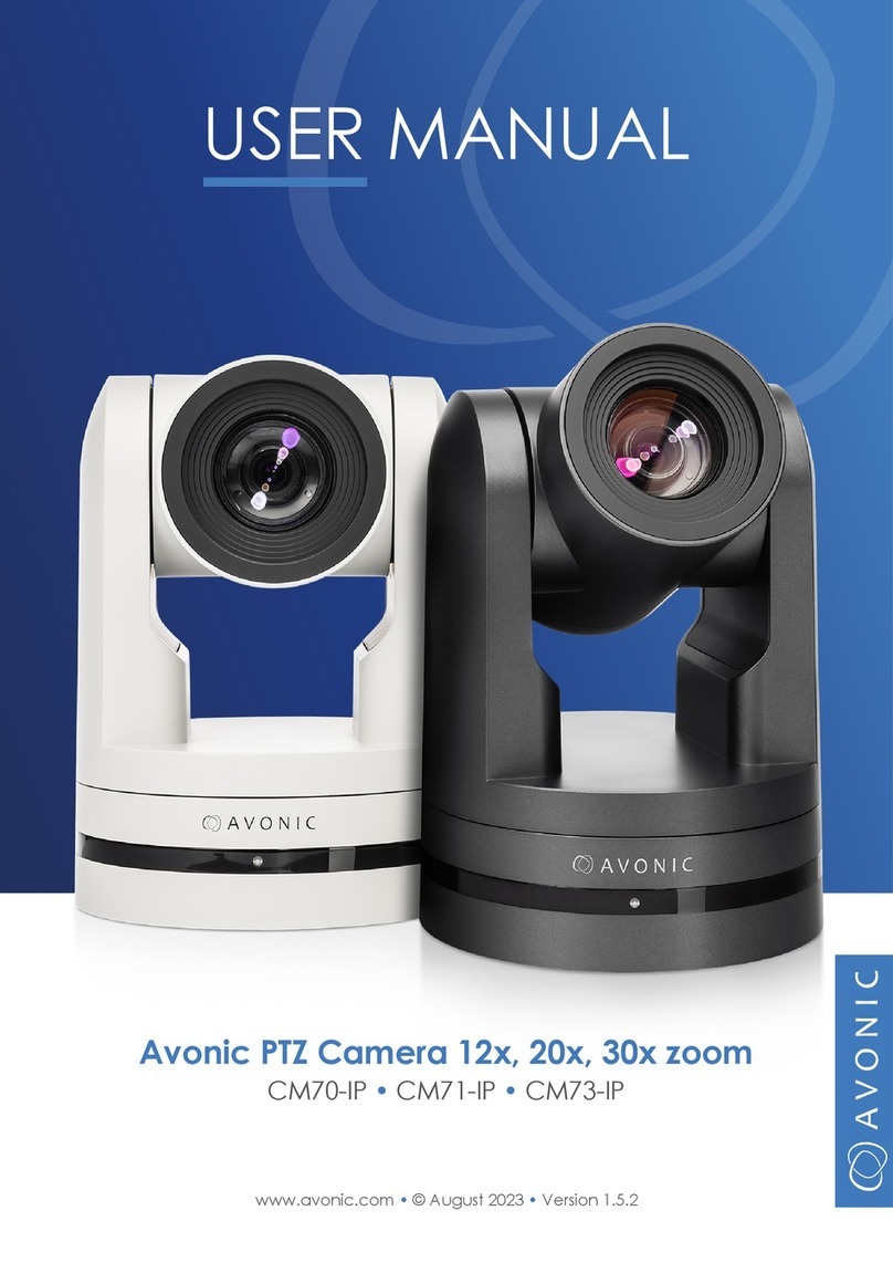
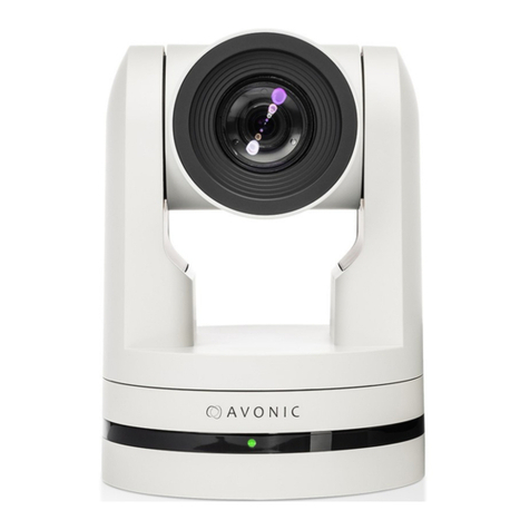
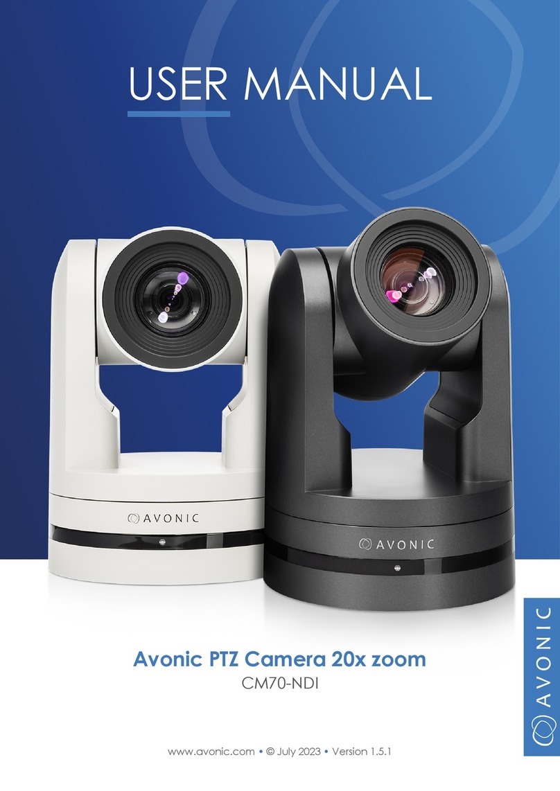
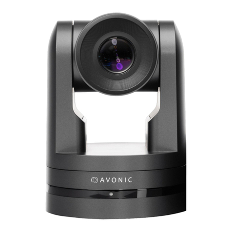
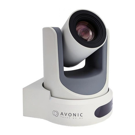
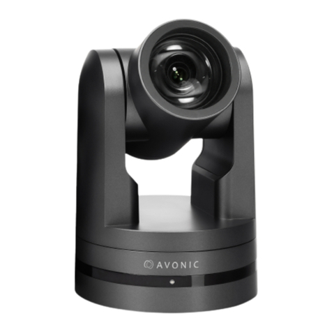
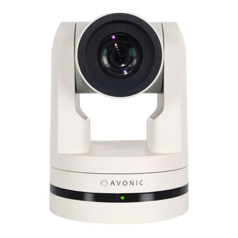
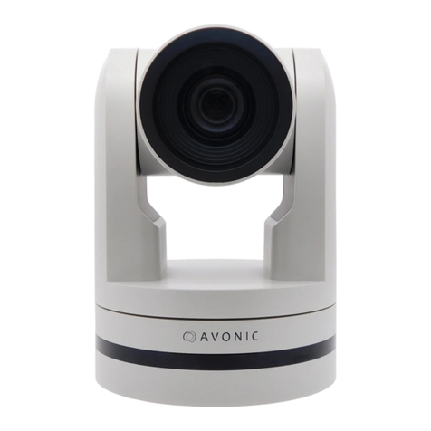
Avonic AV-CM41-VCUC-B User manual

User Manual | Version 1.0.2
www.avonic.com
Video Conference Camera USB2.0 Black
AV-CM4ʤ-VCUC-B

2
CONTENTS
Introduction ............................................................................................................................. 4
Contact . .. .. .. .. .. .. .. .. .. .. .. .. .. .. .. .. .. .. .. .. .. .. .. .. .. .. .. .. .. .. .. .. .. .. .. .. .. .. .. .. .. .. .. .. .. .. .. .. .. .. .. .. .. .. .. .. 4
Join Avonic .. .. .. .. .. .. .. .. .. .. .. .. .. .. .. .. .. .. .. .. .. .. .. .. .. .. .. .. .. .. .. .. .. .. .. .. .. .. .. .. .. .. .. .. .. .. .. .. .. .. .. .. .. .. 4
Safety Notes ............................................................................................................................ 5
Package contents and Accessories ...................................................................... 7
Contents.. .. .. .. .. .. .. .. .. .. .. .. .. .. .. .. .. .. .. .. .. .. .. .. .. .. .. .. .. .. .. .. .. .. .. .. .. .. .. .. .. .. .. .. .. .. .. .. .. .. .. .. .. .. .. .. 7
Handling precautions .. .. .. .. .. .. .. .. .. .. .. .. .. .. .. .. .. .. .. .. .. .. .. .. .. .. .. .. .. .. .. .. .. .. .. .. .. .. .. .. .. .. .. .. .. .. 7
Accessoiries .. .. .. .. .. .. .. .. .. .. .. .. .. .. .. .. .. .. .. .. .. .. .. .. .. .. .. .. .. .. .. .. .. .. .. .. .. .. .. .. .. .. .. .. .. .. .. .. .. .. .. .. .. 7
Product Overview ................................................................................................................ 8
Features .. .. .. .. .. .. .. .. .. .. .. .. .. .. .. .. .. .. .. .. .. .. .. .. .. .. .. .. .. .. .. .. .. .. .. .. .. .. .. .. .. .. .. .. .. .. .. .. .. .. .. .. .. .. .. .. 8
Installation ............................................................................................................................... 9
Connections .. .. .. .. .. .. .. .. .. .. .. .. .. .. .. .. .. .. .. .. .. .. .. .. .. .. .. .. .. .. .. .. .. .. .. .. .. .. .. .. .. .. .. .. .. .. .. .. .. .. .. .. .. 9
System Select Switch . .. .. .. .. .. .. .. .. .. .. .. .. .. .. .. .. .. .. .. .. .. .. .. .. .. .. .. .. .. .. .. .. .. .. .. .. .. .. .. .. .. .. .. .. .. .. 10
RS232 Interface.. .. .. .. .. .. .. .. .. .. .. .. .. .. .. .. .. .. .. .. .. .. .. .. .. .. .. .. .. .. .. .. .. .. .. .. .. .. .. .. .. .. .. .. .. .. .. .. .. .. .. 10
RS232 network connection diagram .. .. .. .. .. .. .. .. .. .. .. .. .. .. .. .. .. .. .. .. .. .. .. .. .. .. .. .. .. .. .. .. .. .. .. 11
RS485 network connection diagram .. .. .. .. .. .. .. .. .. .. .. .. .. .. .. .. .. .. .. .. .. .. .. .. .. .. .. .. .. .. .. .. .. .. .. 11
IP network connection diagram . .. .. .. .. .. .. .. .. .. .. .. .. .. .. .. .. .. .. .. .. .. .. .. .. .. .. .. .. .. .. .. .. .. .. .. .. .. .. 11
Serial Communication Control .. .. .. .. .. .. .. .. .. .. .. .. .. .. .. .. .. .. .. .. .. .. .. .. .. .. .. .. .. .. .. .. .. .. .. .. .. .. .. 12
Operation .................................................................................................................................. 13
Remote controller .. .. .. .. .. .. .. .. .. .. .. .. .. .. .. .. .. .. .. .. .. .. .. .. .. .. .. .. .. .. .. .. .. .. .. .. .. .. .. .. .. .. .. .. .. .. .. .. .. 13
Other Key Combinations . .. .. .. .. .. .. .. .. .. .. .. .. .. .. .. .. .. .. .. .. .. .. .. .. .. .. .. .. .. .. .. .. .. .. .. .. .. .. .. .. .. .. .. 15
OSD Menu ................................................................................................................................. 16
Menu .. .. .. .. .. .. .. .. .. .. .. .. .. .. .. .. .. .. .. .. .. .. .. .. .. .. .. .. .. .. .. .. .. .. .. .. .. .. .. .. .. .. .. .. .. .. .. .. .. .. .. .. .. .. .. .. .. .. 17
Setup .. .. .. .. .. .. .. .. .. .. .. .. .. .. .. .. .. .. .. .. .. .. .. .. .. .. .. .. .. .. .. .. .. .. .. .. .. .. .. .. .. .. .. .. .. .. .. .. .. .. .. .. .. .. .. .. .. .. 17
Camera .. .. .. .. .. .. .. .. .. .. .. .. .. .. .. .. .. .. .. .. .. .. .. .. .. .. .. .. .. .. .. .. .. .. .. .. .. .. .. .. .. .. .. .. .. .. .. .. .. .. .. .. .. .. .. .. 18
PTZ .. .. .. .. .. .. .. .. .. .. .. .. .. .. .. .. .. .. .. .. .. .. .. .. .. .. .. .. .. .. .. .. .. .. .. .. .. .. .. .. .. .. .. .. .. .. .. .. .. .. .. .. .. .. .. .. .. .. .. .. 24
Network .. .. .. .. .. .. .. .. .. .. .. .. .. .. .. .. .. .. .. .. .. .. .. .. .. .. .. .. .. .. .. .. .. .. .. .. .. .. .. .. .. .. .. .. .. .. .. .. .. .. .. .. .. .. .. .. 25
Version . .. .. .. .. .. .. .. .. .. .. .. .. .. .. .. .. .. .. .. .. .. .. .. .. .. .. .. .. .. .. .. .. .. .. .. .. .. .. .. .. .. .. .. .. .. .. .. .. .. .. .. .. .. .. .. .. 25
Restore Default . .. .. .. .. .. .. .. .. .. .. .. .. .. .. .. .. .. .. .. .. .. .. .. .. .. .. .. .. .. .. .. .. .. .. .. .. .. .. .. .. .. .. .. .. .. .. .. .. .. .. 25
WebGUI ....................................................................................................................................... 26
Login.. .. .. .. .. .. .. .. .. .. .. .. .. .. .. .. .. .. .. .. .. .. .. .. .. .. .. .. .. .. .. .. .. .. .. .. .. .. .. .. .. .. .. .. .. .. .. .. .. .. .. .. .. .. .. .. .. .. .. 26
Network .. .. .. .. .. .. .. .. .. .. .. .. .. .. .. .. .. .. .. .. .. .. .. .. .. .. .. .. .. .. .. .. .. .. .. .. .. .. .. .. .. .. .. .. .. .. .. .. .. .. .. .. .. .. .. .. 26
Port Settings .. .. .. .. .. .. .. .. .. .. .. .. .. .. .. .. .. .. .. .. .. .. .. .. .. .. .. .. .. .. .. .. .. .. .. .. .. .. .. .. .. .. .. .. .. .. .. .. .. .. .. .. .. 27
Ethernet and DNS settings .. .. .. .. .. .. .. .. .. .. .. .. .. .. .. .. .. .. .. .. .. .. .. .. .. .. .. .. .. .. .. .. .. .. .. .. .. .. .. .. .. .. 27
www.avonic.com
3
System . .. .. .. .. .. .. .. .. .. .. .. .. .. .. .. .. .. .. .. .. .. .. .. .. .. .. .. .. .. .. .. .. .. .. .. .. .. .. .. .. .. .. .. .. .. .. .. .. .. .. .. .. .. .. .. .. 28
User .. .. .. .. .. .. .. .. .. .. .. .. .. .. .. .. .. .. .. .. .. .. .. .. .. .. .. .. .. .. .. .. .. .. .. .. .. .. .. .. .. .. .. .. .. .. .. .. .. .. .. .. .. .. .. .. .. .. .. 28
Update .. .. .. .. .. .. .. .. .. .. .. .. .. .. .. .. .. .. .. .. .. .. .. .. .. .. .. .. .. .. .. .. .. .. .. .. .. .. .. .. .. .. .. .. .. .. .. .. .. .. .. .. .. .. .. .. .. 28
Default .. .. .. .. .. .. .. .. .. .. .. .. .. .. .. .. .. .. .. .. .. .. .. .. .. .. .. .. .. .. .. .. .. .. .. .. .. .. .. .. .. .. .. .. .. .. .. .. .. .. .. .. .. .. .. .. .. 28
Reboot .. .. .. .. .. .. .. .. .. .. .. .. .. .. .. .. .. .. .. .. .. .. .. .. .. .. .. .. .. .. .. .. .. .. .. .. .. .. .. .. .. .. .. .. .. .. .. .. .. .. .. .. .. .. .. .. .. 29
P/T/Z . .. .. .. .. .. .. .. .. .. .. .. .. .. .. .. .. .. .. .. .. .. .. .. .. .. .. .. .. .. .. .. .. .. .. .. .. .. .. .. .. .. .. .. .. .. .. .. .. .. .. .. .. .. .. .. .. .. .. 29
Maintenance .......................................................................................................................... 30
Camera Maintenance . .. .. .. .. .. .. .. .. .. .. .. .. .. .. .. .. .. .. .. .. .. .. .. .. .. .. .. .. .. .. .. .. .. .. .. .. .. .. .. .. .. .. .. .. .. 30
Unauthorized Use .. .. .. .. .. .. .. .. .. .. .. .. .. .. .. .. .. .. .. .. .. .. .. .. .. .. .. .. .. .. .. .. .. .. .. .. .. .. .. .. .. .. .. .. .. .. .. .. .. 30
Troubleshooting ................................................................................................................... 30
General Advice .. .. .. .. .. .. .. .. .. .. .. .. .. .. .. .. .. .. .. .. .. .. .. .. .. .. .. .. .. .. .. .. .. .. .. .. .. .. .. .. .. .. .. .. .. .. .. .. .. .. .. 30
Power Issues.. .. .. .. .. .. .. .. .. .. .. .. .. .. .. .. .. .. .. .. .. .. .. .. .. .. .. .. .. .. .. .. .. .. .. .. .. .. .. .. .. .. .. .. .. .. .. .. .. .. .. .. .. 30
Image.. .. .. .. .. .. .. .. .. .. .. .. .. .. .. .. .. .. .. .. .. .. .. .. .. .. .. .. .. .. .. .. .. .. .. .. .. .. .. .. .. .. .. .. .. .. .. .. .. .. .. .. .. .. .. .. .. .. 31
Control . .. .. .. .. .. .. .. .. .. .. .. .. .. .. .. .. .. .. .. .. .. .. .. .. .. .. .. .. .. .. .. .. .. .. .. .. .. .. .. .. .. .. .. .. .. .. .. .. .. .. .. .. .. .. .. .. 32
WebGUI . .. .. .. .. .. .. .. .. .. .. .. .. .. .. .. .. .. .. .. .. .. .. .. .. .. .. .. .. .. .. .. .. .. .. .. .. .. .. .. .. .. .. .. .. .. .. .. .. .. .. .. .. .. .. .. .. 32
Visca over Serial properties ......................................................................................... 33
Visca over IP properties and command list ..................................................... 33
Pelco-D Protocol Command List .............................................................................. 43
Pelco-P Protocol Command List ............................................................................... 44
Appendix B Dimensions .................................................................................................. 45
CMOS Image Sensors Characteristics ................................................................. 46
www.avonic.com

4www.avonic.com
www.Facebook.com/
avonicPTZ
INTRODUCTION
Thank you for your Avonic purchase. Before operating this product, please read the manual thoroughly and
retain it for future reference. The manual can be downloaded on www.avonic.com. Save this manual for future
reference.
CONTACT
For any questions or suggestions, contact your reseller or the local distributor of Avonic. Find the local distri-
butor on the website of Avonic. For the most recent version of the manual or datasheet, look at the Avonic
website: www.avonic.com.
JOIN AVONIC
www.Linkedin.com/company/
avonic
www.twitter.com/
avonic

5www.avonic.com
SAFETY NOTES
Important safety information
WARNING: Failure to follow these safety instructions could result in fire, electric shock, injury, or damage to
this Product or other property. Read all the safety information below before using
this Product.
WARNING: Before operating this product, please read the manual thoroughly and retain it for future
reference. The manual can be downloaded on www.avonic.com.
Handling
Handle this Product with care. It is made of metal, glass, and plastic and has sensitive electronic components
inside. this Product can be damaged if dropped, burned, punctured, or crushed, or if it comes in contact with
liquid. If you suspect damage to this Product, discontinue use of this Product, as it may cause overheating or
injury.
WARNING: Do not pick up and move the unit while a tripod is attached. The fitting may break under the
weight of the tripod, which may result in injury.
Installation
Set up this Product on a hard, stable surface or mount it to a wall or ceiling. Only use an Avonic mount for
mounting to a wall or ceiling. Ensure the mounting construction is capable of supporting four times the weight
of the Product. (See ‘General Specifications > Weight product’ in the Product Datasheet for the exact weight.)
Make sure to make use of a safety loop or drop protection that is
capable of preventing the Product from falling if the mounting construction fails. Never install a product
above persons to prevent any risk on injuries when it falls down.
WARNING: In order to maintain adequate ventilation, do not install or place this unit in a bookcase, built-in
cabinet or any other confined space. To prevent risk of electric shock or fire hazard due to overheating, ensure
that curtains and any other materials do not obstruct the ventilation.
WARNING: Check the installation at least once a year. An improper installation could cause the unit to fall
Repairing
Don’t open this Product and don’t attempt to repair this Product yourself. Disassembling this Product may
damage it or may cause injury to you. If this Product is damaged, malfunctions, or comes in contact with liquid,
contact Avonic or an Avonic Authorized Service Provider. Repairs by service providers other than Avonic or an
Avonic Authorized Service Provider may not involve the use of Avonic genuine parts and may affect the safety
and functionality of the device. You can find more information about repairs and service at www.avonic.com.
Power
Power this Product with the included cable and power adapter. Other adapters may not meet applicable
safety standards, and connecting with such adapters could pose a risk of death or injury.
WARNING: Using damaged cables, or using the Product when moisture is present, can cause fire, electric
shock, injury, or damage to this Product or other property. When you power this Product, make sure the cable is
fully inserted into the power adapter before you plug the adapter into a power outlet. It’s important to keep this
Product, the cable, and the power adapter in a well-ventilated area when in use.

6www.avonic.com
Power adapter
To operate the Avonic power adapter safely and reduce the possibility of heat-related injury or damage, plug
the power adapter directly into a power outlet. Don’t use the power adapter in wet locations, and don’t connect
or disconnect the power adapter with wet hands. Stop using the power adapter and any cables if any of the
following conditions exist:
• The power adapter plug or prongs are damaged.
• The cable becomes frayed or otherwise damaged.
• The power adapter is exposed to excessive moisture, or liquid is spilled into the power adapter.
• The power adapter has been dropped, and its enclosure is damaged.
Intended use
This Product shall not be used in the residential area and shall only be installed and operated by experienced
technicians.
Not a medical device
This Product is not a medical device and should not be used as a substitute for professional medical judgment.
It is not designed or intended for use in the diagnosis of disease or other conditions, or in the cure, mitigation,
treatment, or prevention of any condition or disease. Please consult your healthcare provider
prior to making any decisions related to your health.
Explosive and other atmospheric conditions
Using this Product in any area with a potentially explosive atmosphere, such as areas where the air contains
high levels of flammable chemicals, vapours, or particles (such as grain, dust, or metal powders), may be ha-
zardous. Exposing this Product to environments having high concentrations of industrial chemicals,
including near evaporating liquified gasses such as helium, may damage or impair this Product functionality.
Obey all signs and instructions.
High-consequence activities
This device is not intended for use where the failure of the device could lead to death, personal injury, or severe
environmental damage.

7
Nr Quantity Description Avonic SKU
1 1 pc PTZ Camera AV-CM4ʤ-VCUC
2 1 pc Remote Control AV-CM40-RC
3 1 pc USB cable type A to type A AV-USB20-AA
4 1 pc Power Supply 12V/A AV-CM40-PSU
5 1 pc RS232 9-pin D-Sub female to DIN -8 male AV-CM-RS232
Contents
PACKAGE CONTENTS AND ACCESSORIES
www.avonic.com
Be cautious to take the camera by its
base. Do not move the position of the lens
manually! (see pictures) When placing
back the camera in its sealed camera
bag, be sure the lens is in horizontal posi-
tion.
Handling precautions

8
• High-quality wide-angle glass lens, ʤʥx optical zoom and ʪʣʡʧ° horizontal angle view
• High SNR CMOS combined with digital noise reduction, the picture is clear even under low illumination
(0.5 lux @ F1.8) conditions.
• With 1/2.8”high-quality CMOS sensor (2.07 Megapixel) the camera has a resolution of 1920 x 1080p30
and achieves a picture of great quality.
• USB 2.0 up to 1080p30.
• Control the camera with common protocols: VISCA over IP (RJ45), Visca and Pelco-D/P (RS232/
RS485) or IR remote control (included).
• Up to 255 presets with 0.1° accuracy.
PRODUCT OVERVIEW
The Avonic AV-ʶˀʧʤ-VCUC is a high-quality PTZ camera, with USB2.0 output. The camera is designed for fixed
installations and works very well in low light conditions. The camera is equipped with high quality components
like a Panasonic CMOS sensor and a glass lens with ʤʥx optical zoom. Control the camera over RS232 or
RS485 with any controller with VISCA or PELCO support.
Features
www.avonic.com
Accessories
Wall and Ceiling mount
SKU white: AV-MT200-W
SKU black: AV-MT200-B
Ceiling mount
SKU white: AV-MT250-W
SKU black: AV-MT250-B

9
1. RS-485 two-wire serial communication with 2-pin Phoenix connector
2. System Selector (see Installation for more details)
3. RS-232 mini-DIN-8 IN (connect the supplied RS-232 cable)
4. RS-232 mini-DIN-8 OUT for daisy chaining RS-232 connection
5. USB2.0 Type A, UVC video output
6. RJ45 Ethernet connection for IP control or firmware update
7. DC12V power with locking screw (connect the supplied DC PSU)
8. Power ON/OFF
Connections
INSTALLATION
www.avonic.com
1 2 3 4
5 6 7 8

10
CAUTION:
The System Select Switch has no function in the AV-CM4ʤ-VCUC as all the output resolutions are
dictated by the computer to which it has been connected
Power adapter
This equipment is equipped with a 12V/2A DC power supply. Insert the power supply according to the requi-
rements, turn on the power switch.
Power On
Pan-Tilt will rotate to the maximum position of top right after the camera started, then it returns to the
center, the process of initialization is finished. The camera will show its current IR-channel setting and IP
Address on the osd (Note: If the position preset 0 has been stored, the position preset 0 will be called after
initialization). From this point onwards the user can control the camera with the supplied IR remote control,
Serial control using RS232/RS485 or over IP using Visca over IP
RS232 Interface
System Select Switch
www.avonic.com
If you are not using the RS232 9-pin D-Sub female to DIN -8 male cable supplied in the box, connect the
controller to the back of the camera as is shown in the respectively figures below for Windows DB-9 and
Mini-DIN-8. The photo below is a picture of the RS-232 interface of the back of the camera.

11
When connecting multiple cameras through RS-232, use daisy chaining network architecture. Max cable
length for RS-232 is 10-15m.
To connect multiple cameras by RS485, the cameras are attached to a 2-wire twisted pair bus (max length
1200m) that is terminated at both ends with a 120 Ω impedance resistor. The maximum distance from the bus
to the camera or controller is 5m.
RS232 network connection diagram
RS485 network connection diagram
Controller Camera
In Out
RS-232 RS-232 RS-232
In Out In Out
Camera Camera
Connect an Avonic camera to a LAN using a standard switch
Addressing is done via IP, the Visca address in a Visca over ip environment is always 1.
IP network connection diagram
IP controller
Ethernet
Ethernet
Ethernet
Lan Switch
PC
Camera
www.avonic.com

12
COM port settings
In default working mode, an Avonic camera is able to connect to a VISCA controller with RS-232 or RS-485
serial interface.
The camera can be controlled via RS-232, the parameters of RS-232C are as follows:
• Baud rate: 2400/4800/9600/115200
• Start bit: 1 bit.
• Data bit: 8 bits.
• Stop bit: 1 bit.
• Parity bit: none.
The camera can be controlled via RS-485, Half-duplex mode. The parameters are:
• Baud rate: 2400/4800/9600*
• Start bit: 1 bit.
• Data bit: 8 bits.
• Stop bit: 1 bit.
• Parity bit: none.
For command list, see Appendix A
* default value
Serial Communication Control
Network settings
By default the ip address of the camera is 192.168.5.163 with username and password
admin/admin. Avonic IP cameras can be controlled by any device using the Visca over IP
protocol (see command list Appendix A).
The control parameters for the CM40 are as follows:
• IP Address: 192.168.5.163
• Username: admin
• Password: admin
• TCP or UDP port: 1259
• Parity bit: none.
IP Control
www.avonic.com

13
Remote controller
OPERATION
www.avonic.com
a. Set
b. Power
c. Camera select
d. Number Keys
e. Focus + -
f. Auto/Manual Focus
g. Zoom + -
h. Set & Clear Preset
i. PTZ keys (up/down/left/right)
j. Home
k. BLC (Back Light Control) ON/OFF
l. Menu
m. Function Keys (F1/F2/F3/F4)
n. Blank buttons

14
a. Set
This button has no function with this camera.
b. Power
Press the power button to turn on the camera. If the position preset 0 has been stored, the position preset 0
will be called up after initialization. Press the power button again to turn the camera off, it will turn to the back
when turned off, this is called the “privacy mode”.
c. Camera select
Up to 4 different cameras can be controlled with 1 IR remote Control. With the camera select buttons (1,2,3,4)
you can select the IR channel the remote control is using. The default camera IR channel is 1.
To control a camera on first use, please select camera 1 (IR channel 1) on the remote control. To control a
second camera you first need to change the IR channel stored in the camera from 1 to 2.
• First turn off the other camera’s in the room you don’t want to change, to prevent
that other camera’s also get changed accidentally.
• Select camera 1 on the remote control, because the camera is still configured to
listen to IR channel 1.
• Press [*]+[#]+[F2] to change the IR channel inside the camera to IR channel 2
• Select camera 2 on the remote control and see if the camera responds to the remote
control.
Key Combinations: (Default IR address is 1)
[*]+[#]+[F1] : Camera Address No. 1 [*]+[#]+[F3] : Camera Address No. 3
[*]+[#]+[F2] : Camera Address No. 2 [*]+[#]+[F4] : Camera Address No. 4
Note that the F1, F2, F3 and F4 are the colored buttons on the remote.
d. Number Keys
The number keys are used to call presets. Press the number of the preset desired and the camera will res-
pond accordingly (See ‘h’ on how to set & clear presets)
e. Focus + -
Push the button “manual focus” first before using the focus buttons. Focus the camera with the + and – but-
ton. If the camera does not respond check if the camera is set to auto-focus.
f. Auto/Manual Focus
Set the camera in auto-focus or manual-focus. If the camera is configured to auto-focus the buttons “Focus
+ -“ are disabled. When the camera is in “manual focus” modus and the Zoom buttons are used, the camera
automatically switces to auto-focus.
g. Zoom + -
Zoom the camera with these buttons. When the camera is in “manual focus” modus and the Zoom buttons
are used, the camera automatically switches to auto-focus.
www.avonic.com

15
i. PTZ keys (up/down/left/right)
Move the camera in a direction.
j. Home
Set the direction of the camera to a center position.
k. BLC (Back Light Control) ON/OFF
Change the Back light control setting.
l. Menu
The Menu button opens the “On Screen Display (OSD)” menu. This menu is visible on the USB output. If the
menu is not in English, please press [*]+[#]+[4] to change the Menu language to English.
m. Function Keys (F1/F2/F3/F4)
Used to configure the IR channel of the camera. See [c. Camera select] above for instructions.
n. Blank buttons
These buttons have no function with this camera.
[*]+[#]+[4] : Menu set to English
[*]+[#]+[6] : Restore factory defaults
[*]+[#]+[9] : Flip switch (just temporary flip to view the image flipped)
[*]+[#]+[Auto] : Enter into the aging mode, only for quality control purposes
[*]+[#]+[Manual] : Restore the default username, password, and IP address
[#]+[#]+[#] : Clear all presets
Other Key Combinations
www.avonic.com
h. Set & Clear Preset
A preset is a specific position of a camera that you save into the camera. A preset is assigned to a num-
ber from 0-9. To set a preset first point the camera in a specific directing and a specific zoom position. Now
assign the position to a number with the button “Set Preset”. You can call the preset by pressing the number
0-9 on the remote control.
Set Preset: [SET PRESET]+[<number>]
Call Preset: [<number>]
Clear Preset: [CLEAR PRESET]+[<number>]
If the position preset 0 has been stored, this position will be called after initialization.

16
The OSD menu can be accessed by the
Remote Control or an Avonic PTZ controller.
In the following pages, the navigating is
described for using the IR Remote Control.
OSD MENU
www.avonic.com

17
1. MENU
Press [MENU] button to display the main menu on the screen. Use the arrow buttons to move the cursor to
the item to be set. Press the [HOME] button to enter the corresponding sub-menu.
2. SETUP
SETUP
Protocol AUTO / VISCA / PELCO-D / PELCO-P
Visca Address 1 ~ 7
Visca Address Fix ON / OFF
PELCO-P Address 1 ~ 255
PELCO-D Address 1 ~ 255
Baudrate 2400 / 4800 / 9600 / 115200 / 38400
AutoFlip ON/OFF
Select Item
Change Value
[Menu] Back
MENU
Language EN / CN
Setup
Camera
P/T/Z
Video Format
Version
Restore Default
Select Item
Change Value
[Home] Enter
[Menu] Exit
Under setup you can select the protocol you want such as VISCA or PELCO and set manually the VISCA
Adress and PELCO adresses. IF you use the “AUTO” option, the camera will select automatically the protocol
settings. It is also possible to let the camera automatically flip the image on the screen when the AutoFlip is
“ON”.
www.avonic.com

18
3. CAMERA
CAMERA
Exposure
Color
Image
Focus
Noise Reduction
Style Soft / Default / Normal / Clarity / Bright
Select Item
Change Value
[Menu] Back
If you select the option ‘mode’, you will see that you have the following options: Auto, Manual, SAE, AAE
and Bright.
3.1 EXPOSURE
EXPOSURE
Mode Auto / Manual / SAE / AAE / Bright
Iris F11 ~ F1.8 / CLOSE
Shutter 1/25 ~ 1/10000
EV ON / OFF
EV Level -7 ~ +7
BLC ON / OFF
Flicker 50Hz / 60Hz / OFF
G. Limit 0 ~ 15
DRC 1 ~ 8 / CLOSE
Select Item
Change Value
[Menu] Back
Mode: auto
The camera determines the iris and shutter settings. There are a couple of settings to present the
camera with some limits as to what it may do to the image:
EV
on/off and level
EV is Exposure Value, to set this value is to create a quick adjustment to your current exposure
settings if the light conditions require this without actually changing the fundamental values like iris
and shutter. Remember that this is a software setting, take care to not ‘overdo’ the settings or the
picture will become washed out bright or too dark to make out details in shadows.
www.avonic.com

19
Mode: auto - continued
BLC
Back Light Compensation ON/OFF
This setting is to compensate for having to film against bright lighting directly into the lens.
See the pictures below:
BLC: OFF BLC: ON
Flicker
This setting is to set your camera up in such a way that it’s able to cope with the flickering of artificial lighting
in the space where it has to operate. The options are 50Hz, 60Hz and off.
G.Limit
Gain limit is the maximum level of artificial brightness and contrast that the camera may add to the image
automatically. This setting will make a significant difference to the overall picture. Make sure that this setting
is kept ‘within reason’ as it can add noise to the picture in dark areas and produce a washed out greyish
picture.
DRC
Dynamic Range Compression has a similar effect on the picture as the above mentioned gain limit. The DRC
works by compressing the natural dynamic range of the image by taking out the darkest and lightest parts
of the image. This can be a particular helpful setting when the light conditions are challenging. The differen-
ces should be clearly visible in dark parts of the image, they will become lighter/more grey once the level of
DRC is increased.
Manual Mode
In this mode you can set manually the shutter, Iris and DRC options.
Shutter
The first setting to make is the shutter setting. This determines the amount of time per second that the
sensor is exposed. The shutterspeed setting range is 1/25th of a second (40 milliseconds) to 1/10000th of a
second (0.1 milliseconds)
You can imagine that when you shoot video with a shutter time of 1/25th of a second, the video becomes
blurry and overexposed. The faster the shutter is set to open and close, the sharper your filmed object will
become, but the amount of light that falls onto the sensor is also diminished. If you don’t know exactly what
you are doing or the light conditions change a lot, it’s best practice to keep the camera on the automatic
exposure setting.
www.avonic.com

20
Manual Mode - Continued
Iris,
The iris is a tool in a lens that regulates the amount of light that passes through the lens and onto the sensor
by altering the diameter of the hole that the light is entering through. The diameter of the hole is measured in
F-stop value. A higher value lets in less light while a lower setting is more light.
The iris setting affects the length of the depth of field. The higher F-stop you use the deeper your depth of field
– and vice versa. This is because the smaller the aperture, the more focused the light beams will be, resulting
in a more focused image.
DRC
Dynamic Range Compression has a similar effect on the picture as the above mentioned gain limit. The DRC
works by compressing the natural dynamic range of the image by taking out the darkest and lightest parts of
the image. This can be a particular helpful setting when the light conditions are challenging. The differences
should be clearly visible in dark parts of the image, they will become lighter/more grey once the level of DRC
is increased.
SAE Mode, Shutter Auto Exposure
In this mode the shutter speed is user adjustable, the camera itself decides the best iris F-stop value for an
optimal exposure setting.
Keep in mind that the shutter speed is the amount of time that each frame of the sensor has been exposed
to light.
To compensate for poor lighting conditions, it is possible to adjust the DRC or Dynamic Range Compression.
The DRC works by compressing the natural dynamic range of the image by taking out the darkest and ligh-
test parts of the image. This can be a particular helpful setting when the light conditions are challenging. The
differences should be clearly visible in dark parts of the image, they will become lighter/more grey once the
level of DRC is increased.
AAE Mode, Aperture Auto Exposure
The camera will automatically set the shutter speed based on the iris F-stop value (aperture) set by the user.
As the camera determines the preferable shutterspeed it is possible in this mode to turn the antiflicker setting
to the required 50Hz or 60Hz to eliminate the effects of a shutter functioning at 1/50th of a second for
example.
In this mode, both the Gain limit and DRC are available to compensate for challenging light conditions.
Bright mode
This mode is to try and create a decent image when the light conditions are exceptionally poor. In this mode
keep the Bright level, Gain limit and DRC as low as possibly acceptable to avoid getting too much noise in the
picture. If the level of noise in the image becomes unacceptable, noise reduction is available to smooth the
picture over.. (See page 23)
www.avonic.com
Table of contents
Other Avonic Security Camera manuals

Avonic
Avonic CM70-IP User manual

Avonic
Avonic CM60-IP-BOX User manual

Avonic
Avonic CM70-NDI-B User manual

Avonic
Avonic AV-CM40 User manual

Avonic
Avonic CM60-IPU User manual

Avonic
Avonic AV-CM40 User manual

Avonic
Avonic AV-CM60-IPX-BOX User manual

Avonic
Avonic CM71-IP User manual

Avonic
Avonic CM93-IP User manual

Avonic
Avonic CM70-IP User manual

Avonic
Avonic CM93-IP-B User manual

Avonic
Avonic AV-CM40-W User manual

Avonic
Avonic AV-CM40-IP User manual

Avonic
Avonic AV-CM93-NDI-W User manual

Avonic
Avonic CM63-IP User manual

Avonic
Avonic CM70-NDI User manual

Avonic
Avonic CM70-NDI User manual

Avonic
Avonic CM70-NDI User manual

Avonic
Avonic CM7 IP Series User manual

Avonic
Avonic CM70-IP User manual