manuals.online logo
Brands
  1. Home
  2. •
  3. Brands
  4. •
  5. AVT
  6. •
  7. Educational Equipment
  8. •
  9. AVT EDU633 User manual

AVT EDU633 User manual

• automatic display brightness regulation
• alarm clock with snooze function
Specifications
A practical clock kit with an alarm function. Outfitted
with a straightforward LED display and brightness
regulation circuit, conditional to the ambient light, the
Alarm Clock maintains operation even when the
power supply is cut. • simple, two-button control
• time display in hour, minute format
• power supply: 5 VDC (USB B cable - not included)
1
AVT EDU633
You can control the alarm clock with the use of two
buttons: MODE and SET. Diagram picturing the use of
the clock is shown on Figure 3.
To turn off the alarm and the snooze press and hold
the S2 button. The alarm will also turn off after
leaving it unattended for approx. 90 seconds. To
completely turn the alarm on/off press and hold the
S2 button while the clock is in normal mode.
While the clock is working, pressing and holding the
S2 button will turn the alarm on/off. When the alarm
is activated, the display will show the set time for a
few seconds.
The diode set by the minute number shows whether
the alarm is on or off. If the alarm is active, the diode
is on.
The quickest way to learn the functions of this alarm
clock, is to try it in practice. After a short while the
use will become intuitive.
After the alarm starts, pressing either of the buttons
shuts it off, activating the snooze function (the alarm
diode starts flashing). After the alarm starts again,
pressing either of the buttons starts the snooze
function, etc. Really great function for the laid-back...
How to use
Alarm Clock
Educational Soldering Kit
https://bit.ly/3cQsloh
PDF
DOWNLOAD
ZOOM
2
ATMEGA8
1k
1k
1k
100
100
100
100
100
100
100
100
1k
1k
100uF 100nF
100nF
22pF
4.7k
PCF8583P
32kHz
100
4.7k
4.7k
100nF
BAT43 BAT43
FOTO
4.7k
BC557
BC557
BC557
BC557
BC557
PIEZO
PB5(SCK) 19
PB7(XTAL2/TOSC2)
10
PB6(XTAL1/TOSC1)
9
GND
8
VCC
7
AGND
22
AREF
21
AVCC
20
PB4(MISO) 18
PB3(MOSI/OC2) 17
PB2(SS/OC1B) 16
PB1(OC1A) 15
PB0(ICP) 14
PD7(AIN1) 13
PD6(AIN0) 12
PD5(T1) 11
PD4(XCK/T0) 6
PD3(INT1) 5
PD2(INT0) 4
PD1(TXD) 3
PD0(RXD) 2
PC5(ADC5/SCL) 28
PC4(ADC4/SDA) 27
PC3(ADC3) 26
PC2(ADC2) 25
PC1(ADC1) 24
PC0(ADC0) 23
PC6(/RESET)
1
US1
R15
R13
R16
R12
R4
R5
R6
R7
R8
R9
R10
R11
R14
C5 C4C3
C1
R3
A0
3
SDA
5SCL
6
INT 7
OSCI
1
OSCO
2
VSS 4
VDD 8
US2
Q1
+ -
BATT
R18
R1
R2
C2
D1 D2
3
4
1
2
S1
3
4
1
2
S2
-+
USB
1
2
3
4
DISP
a
b
c
d
e
f
g
dp
dig1
dig2
dig3
dig4
cola
colc
PH1
R17
T1
T2
T3
T4
T5
+5V
+5V
+5V
+5V
+5V
+5V
+5V
GND
GND
GND
GND
GND
GND
GND
SDA
SDA
SCL
SCL
32K
S2
S2
S1 S1
A1
A1
A
A
B
B
C
C
D
D
E
E
F
F
G
G
DP
DP
A2
A2
A3
A3
A4
A4
A5
A5
PIEZO
PH PH
PIEZO
+
Figure 1. Schematic diagram
Figure 2. Position of the elements on the printed circuit board
3
Time display
MODE
Item selection Value change
SET MODE
Item selection Value change
SET
MODE
MODE
Set timeNext
Return Set alarm
SET
MODE
Settings menu Turn on the alarm
- long press
- quick press
SET
SET
Figure 3. Diagram picturing the use of the clock
ZOOM ZOOM
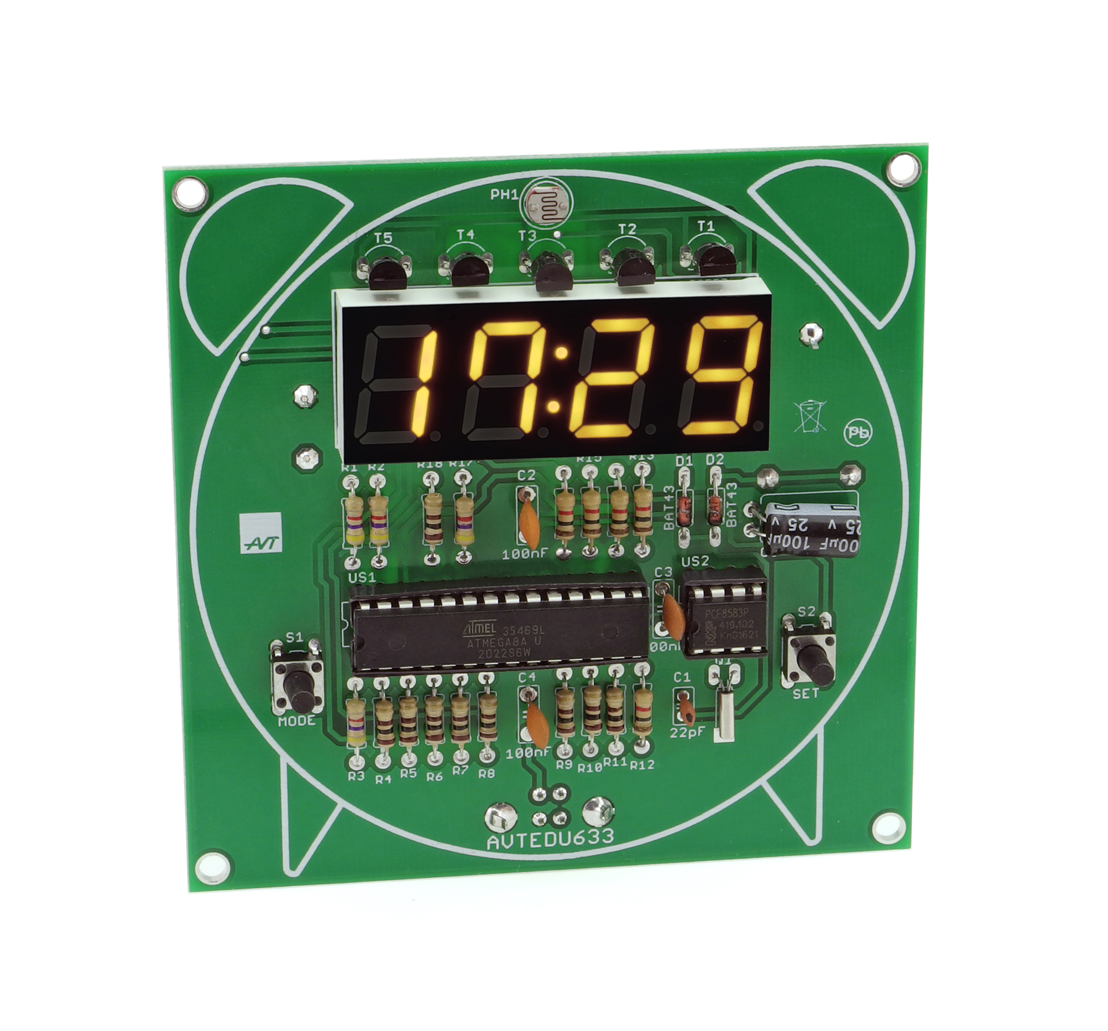
Zalecana kolejność montażu:
R1-R3, R17:.............4,7kΩ resistor (yellow-violet-red-gold)
C2-C4:.......................100nF capacitor (can be marked as 104)
C1:..............................22pF capacitor (can be marked as 22)
US2:...........................PCF8583P + IC socket!
R4-R11, R18:...........100Ω resistor (brown-black-brown-gold)
US1:...........................ATMEGA8A + IC socket!
T1-T5: .......................BC557 or similar !
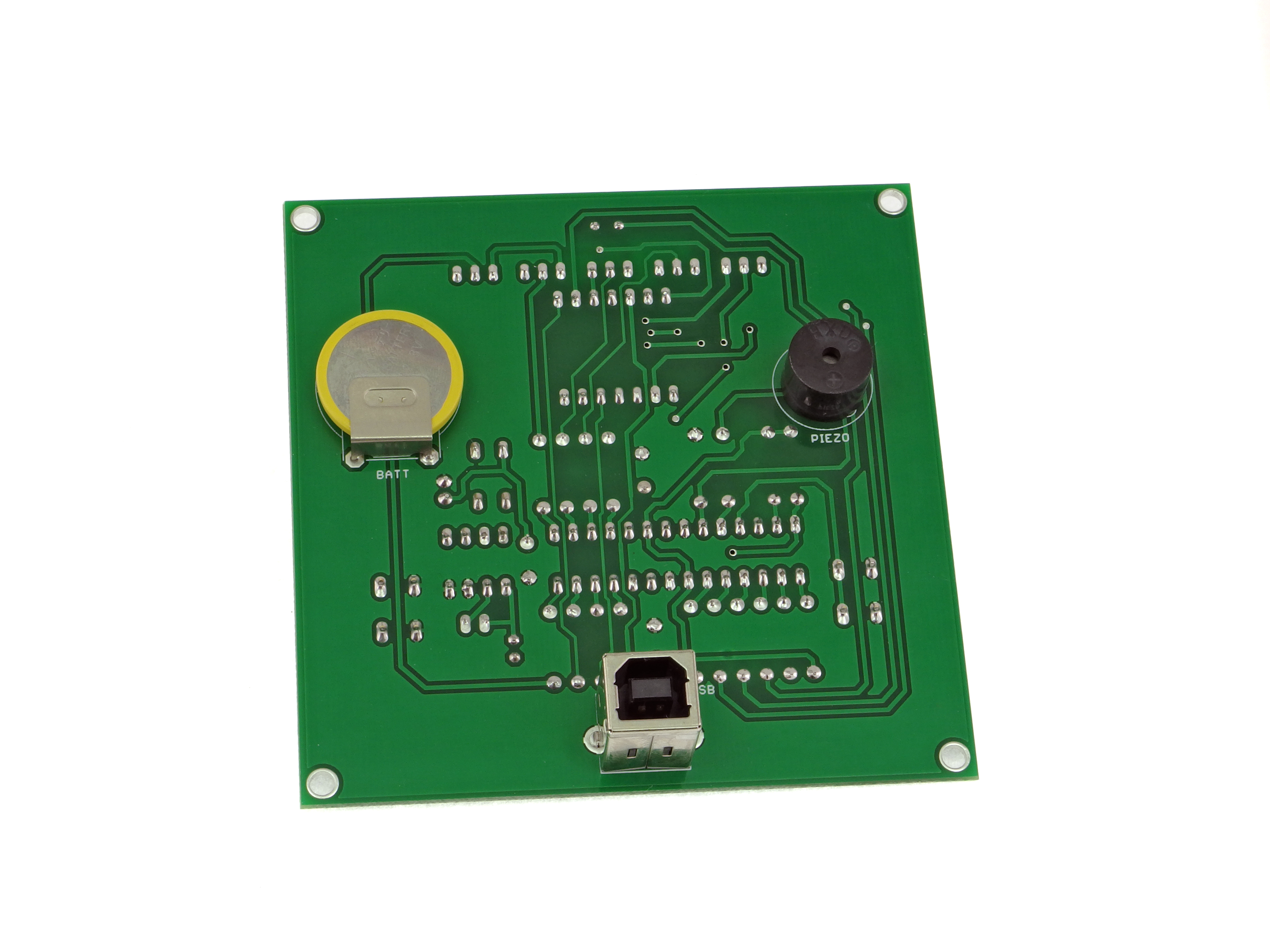
Elements set on the soldering side
PIEZO:.......................buzzer with generator !
C5:..............................100µF capacitor ! (mounted on its side)
DISP:..........................4 number display
S1, S2:.......................microswitch
R12-R16:..................1kΩ resistor (brown-black-red-gold)
USB:...........................USB socket
D1, D2: .....................BAT43 diode!
Q1: .............................32kHz resonator (mounted on its side)
PH1:...........................photoresistor
BATT:.........................CR2032 battery
T1-T5
C5
1
US2
D1
D2
US1
1
4
Assembly and connection of the device not in accordance with the instructions, unauthorized modification of components and any structural modifications may cause damage to the device and
endanger the person using it. In this case, the manufacturer and its authorized representatives shall not be liable for any damages arising directly or indirectly from the use or malfunction of the
product.
AVT SPV reserves the right to make changes without prior notice.
This symbol means do not dispose of your
product with your other household waste.
Instead, you should protect human health
and the environment by handing over your
waste equipment to a designated collection
point for the recycling of waste electrical
and electronic equipment.
Leszczynowa 11 Street,
03-197 Warsaw, Poland
http://avtkits.com/
AVT SPV Sp. z o.o.
Assembly instructions
1
1
2
2
3
3
4
4
Too much tin solder can result in forming a ball
instead of a cone or joining of two adjacent
soldering points.
The cleanness of the soldered surfaces, right
amount of flux in the solder, adequately high
temperature (320-360°C), and sufficient amount of
solder are necessary to complete a correct
bonding.
seconds.
The whole process should take approx. 2-3
and then the soldering iron
Inadequate temperature, amount of tin solder or
impurities can lead to so called “cold solder
joints, i.e. solder and the flux can’t moisten the
two surfaces and the resulting solder point is
fragile and in time will oxidize, break, and stop
working.
of the element near the soldering field
Next, apply tin solder
Touch the tip of the soldering iron to the end
After the cone forms, remove tin solder first,
To get access to assembly tips and high-resolution pictures, download the .pdf file.
Begin by soldering the elements onto the circuit board in order from smallest to largest.
When assembling the elements marked with “!” pay attention to their polarity and placing of the notch.
!
marker marker
marker marker
markermarkermarker
long
lead
straight
side

Popular Educational Equipment manuals by other brands

DISCOVER talking pen user guide

DISCOVER

DISCOVER talking pen user guide

pitsco Smart Buddies 45895 quick start guide

pitsco

pitsco Smart Buddies 45895 quick start guide

RS 3.5 quick start guide

RS

RS 3.5 quick start guide

Quanser QNET 2.0 quick start guide

Quanser

Quanser QNET 2.0 quick start guide

CAE Healthcare METIman user guide

CAE Healthcare

CAE Healthcare METIman user guide

Turning Technologies Pulse quick start guide

Turning Technologies

Turning Technologies Pulse quick start guide

TruCorp AirSim user manual

TruCorp

TruCorp AirSim user manual

LION R.A.C.E. STATION user manual

LION

LION R.A.C.E. STATION user manual

jp.ik LEAPW505 user guide

jp.ik

jp.ik LEAPW505 user guide

laerdal ASL 5000 Lung Solution for SimMan Quick setup guide

laerdal

laerdal ASL 5000 Lung Solution for SimMan Quick setup guide

Rompa GYMTOP 20143 manual

Rompa

Rompa GYMTOP 20143 manual

ScienTECH 2261 Product tutorial

ScienTECH

ScienTECH 2261 Product tutorial

Quanser 6 DOF Hexapod Laboratory guide

Quanser

Quanser 6 DOF Hexapod Laboratory guide

Surefire Flying Model Rocket Kit How to use

Surefire

Surefire Flying Model Rocket Kit How to use

ACROME myCONTROL STEWART PRO user manual

ACROME

ACROME myCONTROL STEWART PRO user manual

SmartMan Baby Manikin manual

SmartMan

SmartMan Baby Manikin manual

Nasco Life/form LF03840U instruction manual

Nasco

Nasco Life/form LF03840U instruction manual

Pitsco Education BUILDERSPACES SPACEPORT Assembly instructions

Pitsco Education

Pitsco Education BUILDERSPACES SPACEPORT Assembly instructions

manuals.online logo
manuals.online logoBrands
  • About & Mission
  • Contact us
  • Privacy Policy
  • Terms and Conditions

Copyright 2025 Manuals.Online. All Rights Reserved.