ACROME myCONTROL STEWART PRO User manual

©2018 Acrome Inc., All rights reserved.
Acrome Inc.
ITU ARI4 Science Park
Maslak, Istanbul
Turkey
Phone: +90 532 132 17 22
Fax: +90 212 285 25 94
Printed in Maslak, Istanbul
For more information on the solutions Acrome Inc. offers, please visit the web site at:
http://www.acrome.net
This document and the software described in it are provided subject to a license agreement.
Neither the software nor this document may be used or copied except as specified under the
terms of that license agreement. All rights are reserved and no part may be reproduced, stored
in a retrieval system or transmitted in any form or by any means, electronic, mechanical,
photocopying, recording, or otherwise, without the prior written permission of Acrome Inc.

Contents
1 OVERVIEW..................................................................................................................................... 4
1.1 System Description........................................................................................................... 4
2 COMPONENTS .............................................................................................................................. 5
2.1 MPU-6050 Six-Axis (Gyro + Accelerometer) ........................................................................ 6
2.2 Linear Actuators .................................................................................................................... 6
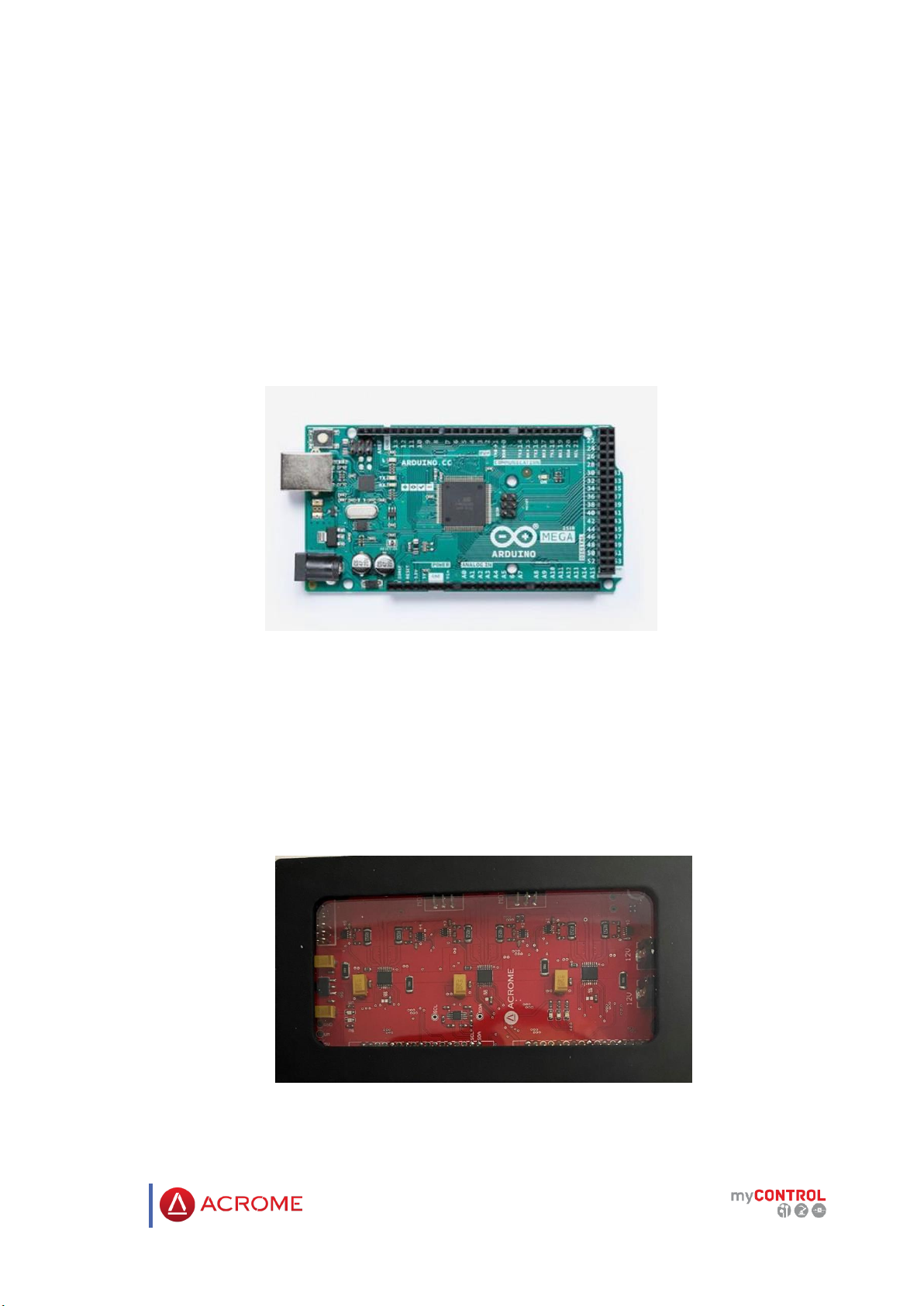
2.3 Arduino Mega 2560............................................................................................................... 7
2.4 ACROME Power Distribution Box ......................................................................................... 7
3 TECHNICAL SPECIFICATIONS........................................................................................................ 8
4 WIRING.......................................................................................................................................... 9
4.1 Cable Names.......................................................................................................................... 9
4.2 Connections......................................................................................................................... 10
5 SETTING UP THE SYSTEM ........................................................................................................... 11
5.1 Getting Started .................................................................................................................... 11
5.2 Stewart_Pro Simulink Model .............................................................................................. 13
6. Device Parameters.................................................................................................................... 15

4
1 OVERVIEW
1.1 System Description
Acrome Stewart Pro consists of 6 Firgelli Feedback Rod Linear Actuators. Also there are 12
cardan joints, 3 special design ball bearing housings as mechanical parts. Both base and
platform plates are made from plexi-glass. Acrome Stewart Pro can be seen in the Figure 1.1.
Figure 1.1: ACROME Stewart Pro
Acrome Stewart Pro can carry up to 500N weight. Linear Actuators are powered by Acrome
Power Distribution Box that also stores motor drivers.

5
2 COMPONENTS
All the main components “ACROME Stewart Pro”are numbered and can be seen in the Figure
2.1. The numbers and the names of elements are listed in the Table 2.1 below.
Table 2.1: Descriptions and numbers of components
Numbers
Description
1
Firgelli Feedback Rod Linear Actuator
2
Cardan Joint
3
Bearing Housing
4
Platform Plate
5
Base Plate
6
Power Distribution Box
7
MPU 6050 Gyro + Accelerometer
Figure 2.1: Components of Stewart Pro

6
2.1 MPU-6050 Six-Axis (Gyro + Accelerometer)
The MPU-6050™ parts are the world’s first Motion Tracking devices designed for the low
power, low cost, and high-performance requirements of smartphones, tablets and wearable
sensors.
Figure 2.2: MPU 6050 Gyro + Accelerometer
2.2 Linear Actuators
Linear Actuators are electromechanical devices that convert electrical signals to movement.
They provide simple and handy solutions to most control and robotic applications.
Figure 2.3: Linear Actuator

7
2.3 Arduino Mega 2560
Arduino is a portable embedded device that allows users to design and control robotic or
mechatronic systems.
The Arduino Mega 2560 is a microcontroller board based on the ATmega2560. It has 54 digital
input/output pins (of which 15 can be used as PWM outputs), 16 analog inputs, 4 UARTs
(hardware serial ports), a 16 MHz crystal oscillator, a USB connection, a power jack, an ICSP
header, and a reset button
Figure 2.4: Arduino Mega
2.4 ACROME Power Distribution Box
Linear Actuators, sensor (Gyro + Accelerometer) and Arduino connections are located on
ACROME power distribution box which is shown in Figure 2.5.
Figure 2.5: ACROME Power Distribution Box

8
3 TECHNICAL SPECIFICATIONS
The Stewart Pro has dimensions and parameters that are shown below. These parameters of
the system will be used in the kinematical model.
Table 3.1: Parameters of the system
Symbols
Definition
Value
Unit
𝒑𝒊
Platform Radius
130
[mm]
𝒃𝒊
Base Radius
170
[mm]
T
Orthogonal Distance Between Two Planes
380-480
[mm]
L
Actuator Length
297-394
[mm]
Figure 3.1: Technical Specifications of Stewart Pro

9
4 WIRING
4.1 Cable Names
Cables which are used in the Stewart Pro system are defined and denominated as seen in Table
4.1 below.
Table 4.1: Cable Descriptions
Cable Names
View of the Cables
Definitions
1. Usb Cable
This cable provides the
connection between PC and
Arduino Mega.
3. Linear Actuator Cable
This cable connects Linear
Actuator to power
distribution box to
transmits PWM waves.
4. Digital I/O Cable
This cable transmits signals
between Arduino and
power distribution box.
5. Gyroscope IMU Cable
This cable connects
gyroscope to power
distribution box in order to
transmit the rotation data
of the platform plate to
Arduino.

10
4.2 Connections
In order to use the system, all cables mentioned above should be connected properly. All the
essential connections among the components are shown in Figure 4.1.
Figure 4.1: Stewart Pro System Connections

11
5 SETTING UP THE SYSTEM
5.1 Getting Started
After the connections are completed successfully, copy "Stewart Pro" folder from "Acrome
Flash USB" to under C:\. And open the "Stewart Pro " folder in MATLAB application.
Figure 5.1: Current Folder
1. After wiring and the connection process, To install Arduino's drivers, download and install
the Arduino IDE from this link.
Figure 5.2: Arduino IDE
2.Connect Arduino Mega 2560 to a USB port of your computer. Check that the Arduino
drivers are properly installed from "Device Manager". The Arduino should appear in Device
Manager as in Figure 5.3. The Comport number may be different.
Figure 5.3: Device Manager
3.To run Stewart Pro simulink models on the Matlab platform with Arduino, you need to install
the “Simulink Support Package for Arduino Hardware" from Add-On Explorer. The "Simulink
Support Package for Arduino Hardware" plug-in is shown in Figure 5.4.

12
Figure 5.4: Simulink Support Package
4. We need a compiler tool for use S-function builder in Simulink models. For this, click on
the Get Add-Ons in the MATLAB window and find the “MATLAB Support for MinGw-w64 C
/ C ++ Compiler” plug-in in the search. The " MATLAB Support for MinGw-w64 C/C ++
Compiler " plug-in is shown in Figure 5.8.
Figure 5.5:MATLAB Support for MinGw-w64 C/C++ Compiler

13
5.2 Stewart_Pro Simulink Model
Please click on “StewartPro.slx” to open. Front panel of “StewartPro.slx” shown in Figure 5.8.
Figure 5.19:Front panel of “Stewart_Pro.slx”
Enable Motors button gives power for each six linear actuators when button is ON. Similarly
cuts off the power when the button is OFF.
There are two displays in the right-bottom corner of the front panel. They indicates the set
positions and actual motor positions.
At the left-top corner of the front panel, program has mode structure to control the Stewart
Pro. Structure has three modes named as “Manual Control”, “Circle”and “Vibration”.
At Manual Control mode, there are six sliders to change X-Y-Z positons and roll-pitch-yaw
orientation angles. User can slide the node on the slider to change values, or also can use the
digital display on the right to insert constant values.
Figure 5.20: Control Sliders in “Manual Control” Mode

14
In “Circle” mode, there is a simple program that changes X-Y positon and Roll-Pitch Orientation
values for a circular path.
With Radius input, user can change the radius of the circular move.
With Speed input, user can change the speed of the path.
There is a radio button with two options at the top of the front panel. User can apply
the circular move for position or orientation.
When the user presses the Enable button, the circular move starts.
Figure 5.21:Circle Mode
When the Simulink model is in Vibration mode, simulates vibration tests in the industry. The
object on the Stewart Pro is tested for vibration. The motors move at high frequency and
provide vibration on the platform

15
6. Device Parameters
In Stewart Pro program, there are some of preset values and variables that affects the
behaviour of the device.
Here, all the preset values and variables are listed.
Name
Description
Default
Value
P Gain
Proportional Gain for PID Control
0,09
I Gain
Integral Gain for PID Control
0,02
D Gain
Derivative Gain for PID Control
0
PWM Duty Cycle Range
± Range Value to keep Duty Cycle value in valid range.
1
Integral Error Range
± Range Value to saturate out-of-range Integral Error.
5
Position Error Range
± Range Value to saturate Position Error in control
algorithm.
25
Friction Value
This value reduces the effect of friction on control
0.3
DeadBand Value
± Tolerance range
0.1
List 5.1: ”Gains and Ranges” in Device Parameters
Name
Description
Default Value
Radius_Platform
Radius value of the Platform Table
130
Radius_Base
Radius value of the Base Plate
170
Theta_Platform
Theta Angle between two mounted
neighbor-joint points on Platform Plate.
25 (in degrees)
Theta_Base
Theta Angle between two mounted
neighbor-joint points on Base Plate.
90 (in degrees)
List 5.2: ”Platform Parameters” in Device Parameters
Name
Description
Data Type
Motor Set Positions
Desired Position Values that comes
from solution algorithms
Double Array with 6
elements.
Motor Actual Positions
Actual Position Values that has been
read from motor feedback
Double Array with 6
elements.

16
Reset Integrator
A control that resets the sum of
Integrator value of Control Algorithm.
Boolean Input
Motor PWM Duty Cycles
Pulse Width Modulation Duty Cycle
values that drive linear actuators to
keep motors in desired lengths.
Double Array with 6
elements.
Enable/Disable Motors
Variables that power-on motors with
“High” value and power-off motors
with “Low” value.
Boolean Array with
6 elements.
Platform_Orientation
Variables that indicate roll-pitch-yaw
values of the center of Platform Plate.
Double Array with 3
elements.
Platform_Position
Variables that indicate X-Y-Z position
values of the center of Platform Plate.
Double Array with 3
elements.
Platform_Rotation_Matrix
Orientation Matrix that includes
position and orientation values of the
center of Platform Plate.
3X3 Matrix.
Leg Lengths
Actual Leg Lengths in millimeters for
each linear actuator.
Double Array with 6
elements.
List 5.3: Miscellaneous Variables in Device Parameters

ACROME Inc.
ITU Science Park, ARI4 Building
No: B204 Koruyolu
Maslak - Istanbul Turkey
For further information on ACROME equipment please contact.
Website: http://www.acrome.net/
e-mail: [email protected]
Telephone: 0212 807 0456
Table of contents
Other ACROME Educational Equipment manuals
Popular Educational Equipment manuals by other brands

DMAI
DMAI AILA Sit & Play user manual

Quanser
Quanser 3 DOF quick start guide

Next Level Racing
Next Level Racing FLIGHT SIMULATOR BOEING MILITARY EDITION instruction manual

Community Playthings
Community Playthings H525 Product guide

PASCO
PASCO ME-6989 instruction manual

Tensegri-Teach
Tensegri-Teach X-Strut Assembly instructions

adafruit learning system
adafruit learning system Bone Box Guide

Sphero
Sphero indi Getting started

Nasco Healthcare
Nasco Healthcare DANi LF04500 instruction manual

National Instruments
National Instruments Quanser QNET MI quick start guide

ChordBuddy
ChordBuddy ChordBuddy troubleshooting guide

MakeKit
MakeKit MD2 Dronekit manual