REPLIGEN XCell ATF Series User manual

XCellTM ATF System
With C410:V4B Controller
USER GUIDE
XCell™ATF4 | XCell™ATF6 | XCell™ ATF10

XCellTM ATF System with C410:V4B Controller User Guide
The information contained in this document is subject to change without notice.
Copyright © 2019 Repligen Corporation (XCell™ ATF technology acquired by Repligen in
June, 2014)
Repligen Corporation makes no warranty of any kind with regard to this material, including, but
not limited to, the implied warranties of merchantability and fitness for a particular purpose.
Repligen Corporation shall not be liable for errors contained herein or for incidental or
consequential damages in connection with the furnishing, performance, or use of this material.
No part of this document may be photocopied, reproduced, or translated to another language
without the prior written consent of Repligen Corporation.
For further information, please contact Repligen Corporation.
www.repligen.com
Revision History
XCell™ ATF System with C410 Controller, Version v4B Release 2
C410v4B User Guide
Document Revision 2

XCellTM ATF System with C410:V4B Controller User Guide
Contents
1.0 Description of the XCell™ ATF (Alternating Tangential Flow) System and Process ..................1
1.1 XCellTM ATF System Pump Cycle ....................................................................................3
1.2 XCell™ ATF System Control Scope and Objectives ........................................................5
2.0 Utility Requirements.............................................................................................................5
3.0 Dimensions and Weight........................................................................................................6
4.0 XCell™ ATF Pump Housing Assemblies...................................................................................7
See Appendix 7 for list of spares and accessories ........................................................................12
5.0 XCellTM C410v4B Controller Layout ......................................................................................17
5.1 General Layout.............................................................................................................17
5.2 Filtration Assembly (Stainless Steel)............................................................................18
5.3 Pneumatics Box (P-Box) Components .........................................................................18
5.4 Electrical Box (E-Box) ...................................................................................................18
5.5 Power Box (Power Separation) Components ..............................................................20
5.6 Primary Pneumatic Services.........................................................................................20
5.7 Primary Electric Services..............................................................................................21
5.8 Signal............................................................................................................................21
6.0 C410v4B Controller Process and Control..............................................................................22
6.1 Control Overview .........................................................................................................22
6.2 Control Functional Algorithms.....................................................................................24
6.3 Interface and Screens ..................................................................................................25
6.4 Startup .........................................................................................................................50
6.5 Examples ......................................................................................................................52
7.0 XCell™ ATF Hollow Fiber Module and Diaphragm Replacement............................................54
7.1 Separating the Filtration Assembly from the bioreactor.............................................54
7.2 HFM removal................................................................................................................54
7.3 HFM insertion ..............................................................................................................55
7.4 Screen Module replacement .......................................................................................56
7.5 Diaphragm replacement..............................................................................................56
7.6 Assembly......................................................................................................................57
7.7 Use ...............................................................................................................................57
8.0 Sterilization........................................................................................................................58
8.1 Preparation of Filtration Assembly for Autoclaving ....................................................58
8.2 Autoclave Cycle............................................................................................................59

XCellTM ATF System with C410:V4B Controller User Guide
8.3 Sterilization of Filtrate / Harvest line...........................................................................60
9.0 Connection to Bioreactor (ATF-to-Bioreactor)......................................................................61
9.1 Hard Connection ..........................................................................................................61
10.0 Maintenance......................................................................................................................62
10.1 Diaphragm....................................................................................................................62
10.2 Pump Air Inlet Filter.....................................................................................................62
10.3 “O” Rings, gaskets and Quick Connects.......................................................................62
Appendix 1: Cycle time vs. Flow rate ..........................................................................................63
Appendix 2: Access levels to the C410v4B controller ...................................................................64
Appendix 3: Controller Lists: Alarm, Warning, Inputs & Outputs.................................................71
Appendix 4: Profinet Communication .........................................................................................73
Appendix 5: Profibus Communication.........................................................................................75
Appendix 6: Delta V Example configuration ................................................................................96
Appendix 7: OPC Communication ............................................................................................. 103
Appendix 8: Audit Trail (If Equipped) ........................................................................................ 113
Appendix 9: EU Declaration of Conformity................................................................................ 116
Appendix 10: UL Listing............................................................................................................ 119
Appendix 11: Spares List .......................................................................................................... 120

XCellTM ATF System with C410:V4B Controller User Guide
1
1.0 Description of the XCell™ ATF (Alternating Tangential Flow) System
and Process
The XCell™ ATF System provides an efficient means for fractionation of various mixtures. It may
include the separation of mammalian Cells (~ 10 microns in size) from culture medium, the
separation of large particles such as micro carriers (~ 200 microns in size) from a suspension
medium, or separation of some molecules from other molecules in a suspension. The user guide
details the use of the XCell™ ATF System, with the C410v4B Controller for the separation of such
components using hollow fiber filtration.
The system is designed to improve the efficiency of cell culture processing by allowing for the
generation of high viable cell densities. The system can enable continuous processing and is
available in stainless steel and single-use formats. Two primary components, the C410v4B
controller and the ATF pump housing, which in comprised of a diaphragm pump, filter housing
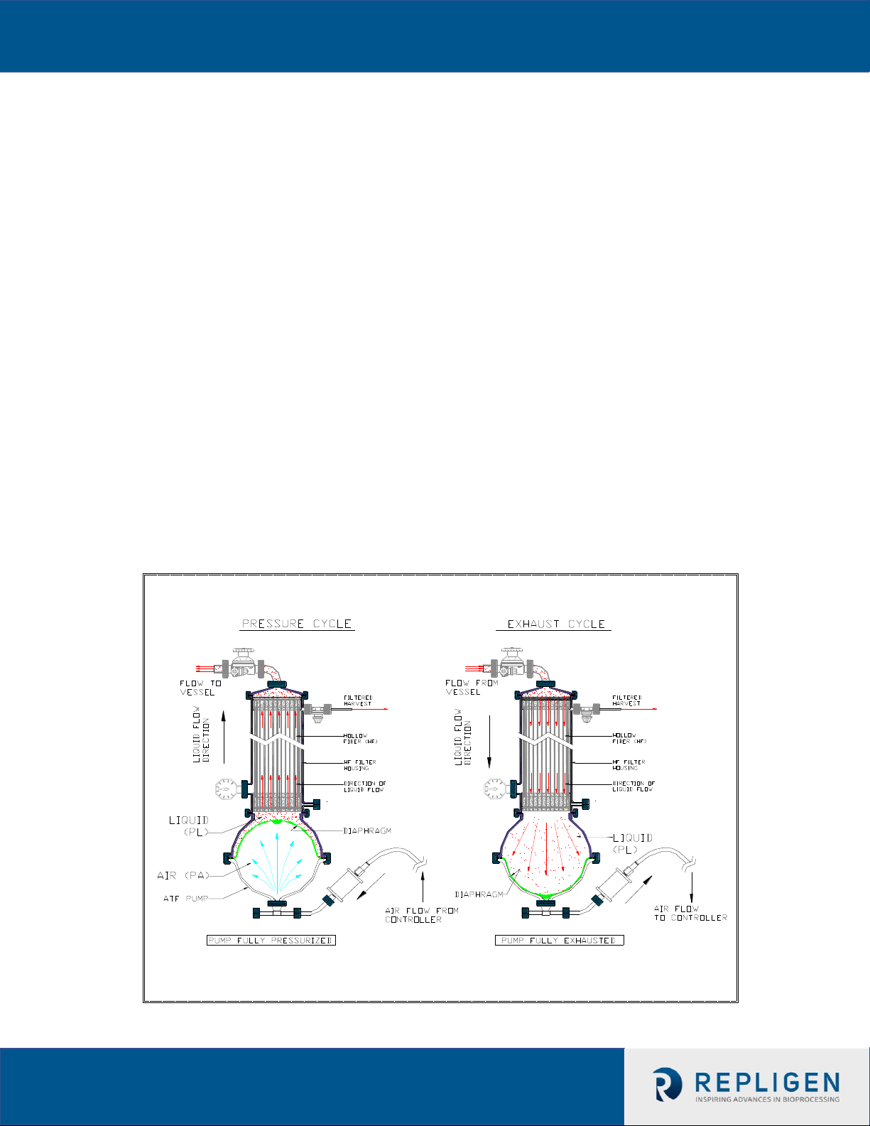
and a hollow fiber filter, are used for desired operation. The controller functions to control the
ATF (Alternating Tangential Flow) action by controlling the movement of the diaphragm pump,
through control of pressurization and exhaust (vacuum) to allow the up and down motion of the
diaphragm in the pump housing. This action displaces a known volume of cell culture material
within the retentate side of the hollow fibers. A separate pump continuously removes cell-free
permeate from the system. Primary components of the current controller include a PLC
(Programmable Logic Controller) with a HMI (Human Machine Interface) to control the
components used in generating the alternating tangential flow action.
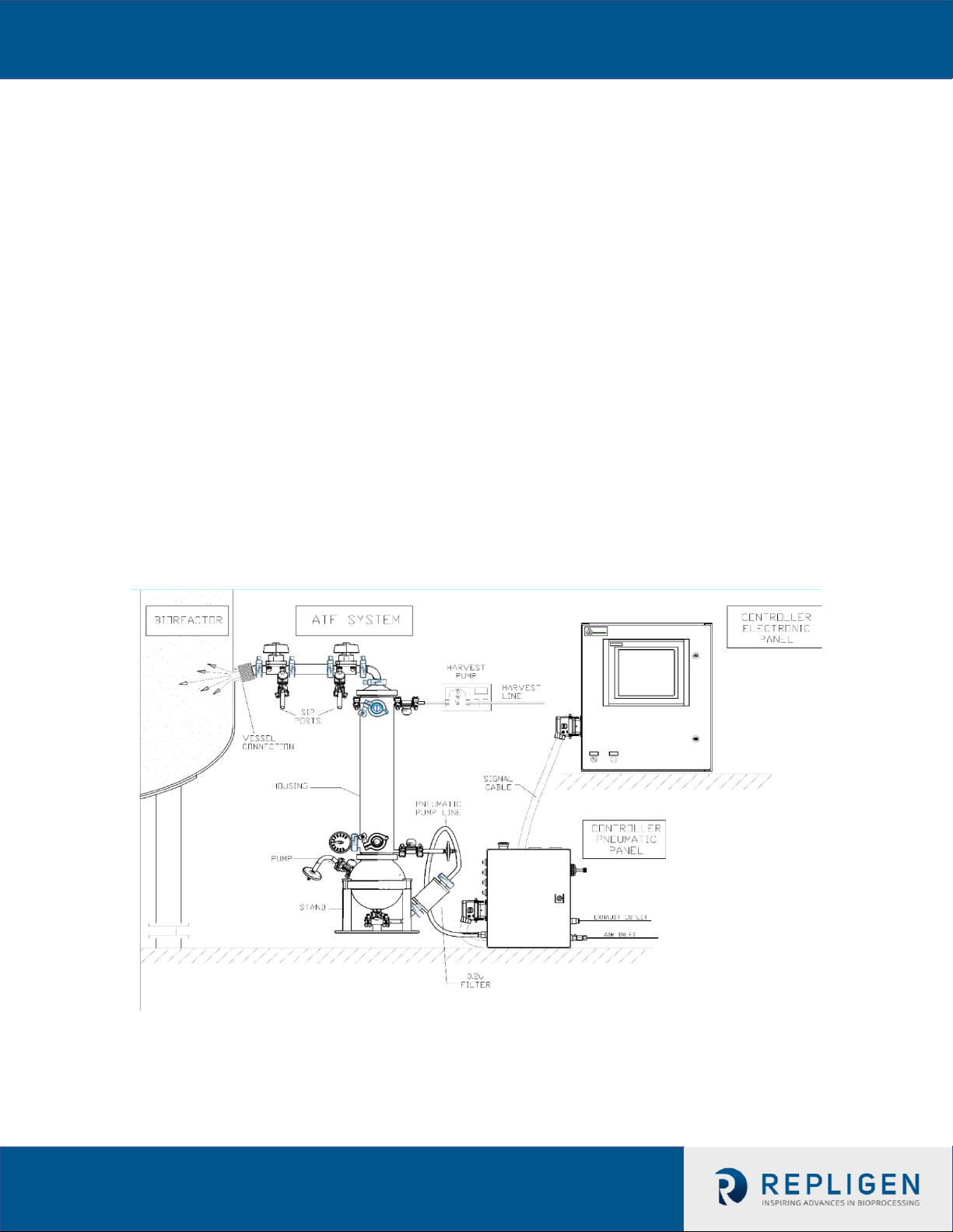
This User Guide pertains to both the Stainless Steel Filtration Assemblies and the XCell™ ATF
Single-use devices, meaning that the C410v4B Controller information relates to the operation of
both the stainless steel and single-use ATF devices. (Figure 1).
•Controller: a dedicated controller used to control and monitor XCell ATF System activity. It
also provides the means for connecting to and controlling pressure and vacuum utilities.
•Filtration Assembly: an assembly of two major elements, a stainless steel filter housing and
a silicone diaphragm pump:
-Filter Housing: housing containing the filtration element, either a hollow fiber module (HFM) or
screen module (SM).
-Diaphragm Pump: spherical housing in which a diaphragm membrane is moved up and down by
pressurized air or vacuum, creating alternating flow.
-Single-use Device: the filter housing, hollow fiber filter and diaphragm pump are combined into
a single polycarbonate device. At this point in time the SM is not available as a single-use device.
Please see the XCell™ ATF Start-Up Guide for additional information on the single-use devcies.
The Filtration Assembly includes the following components for each process application:
-A2B Connection Assembly:tubing assembly connecting the Filtration Assembly to a bioreactor or
process vessel
-Bioreactor Adaptor: adaptor between the Connection Assembly and bioreactor port. Typical
ports/connectors/adaptors for stainless steel bioreactors include an Ingold-type port, triclamp
or, if a single use bioreactor (SUB), then, a disposable aseptic connector (DAC) or equivalent.

XCellTM ATF System with C410:V4B Controller User Guide
2
A typical configuration of the XCell™ ATF System is shown in Figure 1. The Filter Housing accepts
either HFM, with pore sizes from 750kD to ~0.2 micron, or a SM for fractionation of larger
particles, >70 microns. The separating element, the HFM or SM, is positioned between a process
vessel or a bioreactor at one end and the Diaphragm Pump at the other end. The vessel serves as
a storage container for the content to be filtered. The Diaphragm Pump provides the means for
generating alternating tangential flow (ATF), moving the contents of the vessel back and forth,
between the vessel and pump, through the hollow fibers of the HFM or through the SM. The
XCell™ ATF process provides the means for generating rapid, low shear, tangential flow, allowing
for retention of the larger components (i.e.- cells) and filtration of smaller components (i.e. –
media components).
A filtrate pump as shown in Figure 1 is used for controlled removal of a filtered stream. The
unfiltered material remains in the system. Only a single connection is required between the
XCell™ ATF System and the vessel. As shown in Figure 1, the connection can be through a side
port (or bottom port) commonly configured on large scale stainless steel or single-use
bioreactors, or through the head plate as typical with smaller bioreactors. When placed next to
the vessel, only a short connection, commonly referred to as the A2B Connection, is required
between the XCell™ ATF system and the vessel. This connection can be hard piped or soft piped
and is made in a sterile manner. The filtration process remains closed and therefore sterility
between the vessel and the XCell™ ATF System is maintained.
Figure 1. Filtration Assembly Connection to C410v4B Controller and a Bioreactor Side Port
Note: The XCell™ ATF C410v4B Controller has one additional enclosure, the power box (P-box)
which houses the high voltage electrical components (not displayed here). Please reference the
XCell™ ATF Single-use Start up Guide for proper single-use connectivity.

XCellTM ATF System with C410:V4B Controller User Guide
3
1.1 XCellTM ATF System Pump Cycle
The Diaphragm Pump is the heart of the XCell™ ATF System process. It produces an
alternating flow through the HFM (lumen side) or SM. The XCell™ ATF System provides a
pulsating, reversible, flow of liquid, back and forth, between the process vessel and the
Diaphragm Pump. The following is a description of that process:
The Diaphragm Pump is partitioned into two chambers with a flexible diaphragm, Figure
2. One of the pump chambers, the Pump Liquid (PL) chamber is connected to the Filter
Housing, which, in turn, is connected to the process vessel. Therefore, any flow between
the Diaphragm Pump and process vessel will be through the filtration device. The second
pump chamber, the Pump Air (PA) chamber, is connected to the pump flow control
system. Typically, controlled addition of compressed air into the PA chamber increases
the pressure in the chamber relative to the process vessel, forcing the flexible diaphragm
partitioning the two chambers to move into the PL chamber and towards the vessel.
Liquid in the PL chamber is forced through the filter to the process vessel. The flow
through the HFM (lumen side) generates tangential flow in one direction. This pumping
phase (or cycle) in the direction of the bioreactor is called the Pressure Cycle. Inversely,
with a pressurized process vessel relative to PA or PL, or with an external vacuum supply,
liquid will flow in the reverse direction, from process vessel, through the HFM (lumen
side), to the PL chamber, generating tangential flow in the other direction. This pumping
phase (or cycle) in the direction of the XCell™ ATF pump is called the Exhaust Cycle. These
alternating pump cycles are then repeated continuously. See Figure 2.
Figure 2. XCell™ ATF System Pump Cycles

XCellTM ATF System with C410:V4B Controller User Guide
4
Note on the Exhaust Cycle:
WARNING
Glass bioreactors or single-use bioreactors (SUBs), unless otherwise specified by the
manufacturer of the vessel, should not be pressurized. Such vessels can explode if
pressurized.
If a vessel is being operated without positive pressure the XCell™ ATF requires a vacuum
(negative pressure) to move the diaphragm to its lowest position. The PA chamber can then be
alternately pressurized and evacuated to produce XCell™ ATF action while maintaining the
process vessel at atmospheric pressure.
Conversely, when using a vessel that that is operated under positive pressure, the vessel pressure
can be used to drive the liquid from the vessel to the PL chamber. When vessel pressure is
limited, it may be supplemented with vacuum. In either of the above schemes, one is driving the
liquid from the vessel to the Diaphragm Pump by increasing the pressure in the vessel relative to
the Diaphragm Pump. Even with positive vessel pressure assisting with diaphragm deflation,
vacuum is generally required to ensure proper ATF operation
WARNING
When using a glass vessel or SUB, be sure to maintain an unrestricted vent from the
vessel. In the case a diaphragm fails, the air flow into the Diaphragm Pump will proceed
through the HFM or SM into the vessel. A free exhaust from the vessel will minimize the
buildup of pressure in the vessel.

XCellTM ATF System with C410:V4B Controller User Guide
5
1.2 XCell™ ATF System Control Scope and Objectives
The C410 v4 Controller provides the process control functionality of the stainless steel
XCell™ ATF 4 System, XCell™ ATF 6 System, XCell™ ATF 10 System and the XCell™ ATF 6
and 10 Single-use devices. The XCell™ ATF C410v4B controller is designed to:
1. Control ATF flow rates in both pressure and exhaust cycles
2. Provide a user interface capability for XCell™ ATF System control and monitoring
3. Set-up and select operational parameters
4. Display real-time process data and Alarms for error conditions
5. Provide “Batch control” and user hierarchy
6. Have PLC software upgrades in the field by replacing memory modules
7. Have 3 major enclosures, an Electronics Box (E-Box) a Pneumatics Box (P-Box) and a
Power Box
8. Allow the E-Box to operate an XCell™ ATF 4, 6 and 10 systems and XCell™ ATF Single-use
6 and 10 devices using custom software
9. Allow the P-Box hardware and process parameters to be specific to the size of the
particular XCell™ ATF System being controlled.
Control principles are detailed in Section 6.
2.0 Utility Requirements
UTILITY
REQUIREMENT
ADDITIONAL CONSIDERATIONS
PRIMARY
COMPRESSED AIR
Maximum 90 psig /
6.1 bar
Oil free, dry, filtered gas, i.e., medical
grade air
SECONDARY
PRESSURE
Typically: 35 psi / 2.4bar,
Regulated oil free, dry, filtered air
VACUUM SERVICE
Minimum -12.5 psig
Vacuum supplied by a Repligen or
customer supplied local pump capable of
maintaining ~-12.5 psig with nominal
flow as follows:
XCell™ ATF4 - 40L/min
XCell™ ATF6 – 60L/min
XCell™ ATF10 – 200L/min
Pump should be clean room compatible
EXHAUST
Untreated discharge or user specified
ELECTRICAL
100-240V AC, 50/60Hz
NA
ENVIRONMENT:
Temperature: 0-50°C
Relative Humidity: 0 –80
% RH
NA
STEAM (SIP)
~30lbs/hr.
Applicable only to a steamable
connection between XCell™ ATF and
bioreactor vessel
CONDENSATE DRAIN
For SIP condensate drainage

XCellTM ATF System with C410:V4B Controller User Guide
6
3.0 Dimensions and Weight
COMPONENT
DIMENSIONS
DESCRIPTION
H
W
D
C410v4B Controller
inches
PNEUMATIC BOX
13
10.5
8
Includes all plugs and connectors.
ELECTRIC BOX
24
24
9
(Controls) Includes all plugs and connectors.
POWER BOX
13
10.5
8
(Power Separation) Includes all plugs and connectors.
Filtration Assembly
Fully assembled system
XCell™ ATF 4 System
24
6
6x10
Indicated dimensions are estimates for the Filtration
Assembly, as the connection to the bioreactor, the
connections to the controller and to accessories can
affect height and effective area.
XCell™ ATF 4MC
System
44
10
8x12
XCell™ ATF 6 System
44
10
8x12
XCell™ ATF 10lgcy
System
44
14
14x20
XCell™ ATF 10 System
44
14
14x20
XCell™ ATF 6 Single-
use Device
38
12
10
XCell™ ATF 10 Single-
use Device
38
18
16
C410v4B Controller
WEIGHT (Kg)
COMMENTS
PNEUMATIC BOX
~13
ELECTRIC BOX (Controls)
~23
POWER BOX
~12
(Power Separation)
Filtration Assembly
XCell™ ATF 4 System
~6
Weight does not include the weight of any
liquid, filter or connection between the
Filtration Assembly and the vessel
XCell™ ATF 4MC System
~14
XCell™ ATF 6 System
~14
XCell™ ATF 10lgcy System
~30
XCell™ ATF 10 System
~40
XCell™ ATF 6 Single-use
Device
~ 5
Does not include the weight of liquid and A2B
connectors
XCell™ ATF 10 Single-use
Device
~ 18

XCellTM ATF System with C410:V4B Controller User Guide
7
4.0 XCell™ ATF Pump Housing Assemblies
The Filtration Assembly of XCell™ ATF pump housing is shown in Figure 3. Certain parts may vary,
depending on requirements and specifications. Optional components for the XCell™ ATF housing
include bioreactor connection kits, pressure transducers, vacuum pump, and options for sanitary
diaphragm valves. All are available upon request.
Figure 4a. Exploded View of XCell™ ATF 10 System Filtration Assembly (P/N ATF10:PH‐GMP)

XCellTM ATF System with C410:V4B Controller User Guide
8
Table 4a. XCell™ ATF 10 Pump Housing Parts List
Note: C-CLAMP (Hemisphere) Items #20,21 should be torqued to 20-25 ft-lbs with 1" wrench flats
See Appendix 7 for list of spares and accessories
ITEM
M
NO.
DESCRIPTION
Material
QTY.
1
ASME Clamp, Assembly, XCell™
ATF10
316 SS
2
2
Pump Hemisphere Air Side,
XCell™ ATF10
SA479 316L SS
1
3
Lifting Handle, Assembly, XCell™
ATF10
316 SS
1
4
Pump Hemisphere Liquid Side,
Assembly, XCell™ ATF10
316 SS
1
5
Filter Housing Assembly, XCell™
ATF10
316 SS
1
6
Stand, Assembly, XCell™ ATF10
316 SS
1
7
Diaphragm, Pump, XCell™ ATF10
50A P.C. Silicone
1
8
0.295" C/S x 6.835" ID x 7.425" OD
O-Ring, 50A Hardness, Clear
Silicone
2
9
90 Degree Elbow, 1.5TC
316 SS
1
10
Sanitary Gasket, 1 1/2" TC
EPDM
5
11
Clamp, Sanitary, 1 1/2" TC
304 SS
5
12
Sanitary Gasket, 3/4" TC
EPDM
4
13
Sanitary Gasket, 1/2" TC
EPDM
3
14
Clamp, Sanitary 1/2-3/4" TC
304 SS
7
15
Sanitary Cap 3/4"
316 SS
2
16
Sanitary Diaphragm Valve, 1/2"
w/TC ends
316 SS
3
17
Window, Sanitary 1.5"TC
AISI Type 316LSS
2
18
Pressure Gauge, 1.5" TC, 30 psi
SS
1
19
45 deg Elbow, 3/4" TC
SS
1
20
C Clamp w/ Lock-B, Assembly,
XCell™ ATF10
316 SS
3
21
C Clamp w/ Lock-A, Assembly,
XCell™ ATF10
316 SS
3
22
Air Inlet Filter, 0.2 micron, 1/2" TC
Ends
PVDF
1
23
Instrument Tee, 1.5" x 2X 3/4" TC
316 SS
1
24
Reducer, XCell™ ATF10
SA479 316L SS
1
25
Spectrum F10 2 Micron PES
Hollow Fiber Cartridge
NA
1
26
3/8” Hex Bit Socket, 3/8” Drive
Alloy Steel
1

XCellTM ATF System with C410:V4B Controller User Guide
9
Figure 4b. Exploded View of XCell™ ATF 10 Single-use Device with 0.2u PES Hollow Fiber Filter

XCellTM ATF System with C410:V4B Controller User Guide
10
Table 4b. XCell™ ATF 10 Single-use Device Components
Item
DESCRIPTION
MATERIAL
QTY
1
Housing Tube Assembly, suATF10
Polycarbonate (Lexan) HPS6
1
2
Spectrum F10 2 Micron PES Hollow Fiber
Cartridge
NA
1
3
0.295” C/S x 6.835” ID x 7.425” OD O-Ring, 50A
Hardness, Clear
Silicone
2
4
Reducer, Spectrum, su ATF10
Polycarbonate (Lexan)) HPS6
1
5
Liquid Side Pump Hemisphere Assembly, su
ATF10
Polycarbonate (Lexan) HPS6
1
6
Diaphragm, Pump, ATF10
50A P.C. Silicone: BlueStar LSR
4350
1
7
Pump Hemisphere, Air Side, suATF10
Polycarbonate (Lexan) HPS6
1
8
1”TC Bio Clamp, Glass Filled Nylon
GF Nylon
10
9
1” Silicone Sanitary Gasket
Silicone
4
10
Pump Lock Ring, suATF10
Silicone
1
11
GE ReadyMate to 1” TC
Polycarbonate
3
12
Sanitary Gasket, Silicone
Silicone
3
13
XCell ATF 10 Branding Label
Vinyl Decal
1
14
8” TC BioClamp, Glass Filled Nylon
GF Nylon
2
15
U Adapter, 1.5” Sanitary Fittings
PVDF
1
16
Aseptiquik x Insert, 1.5’ sanitary
Polycarbonate
2
17
Adapter, 1” MNPT x 1” Hosebarb
PVDF
1
18
Sanitary Fitting Adapter, 1” YC x 1” Hosebarb
PP
1
19
Steridyne 0.2um Filter Capsule, 1”x 3/4” TC
Flanges
PP
1
20
Oetiker Clamp, 1 3/8” to 1 1/2”
304 SS
1
21
Oetiker Clamp 1 15/64” to 1 23/64”
304 SS
1
22
High Pressure EVA tubing, 1” ID x 18” L
EVA
1.5FT
23
Bottom Lift Label, XcellsuATF10
Vinyl
1
24
Top Lift Label, XCell suATF10
Vinyl
1
25
Henkel Loctite AA-3944 UV Adhesive, 25ml
syringe
UV Adhesive
0.02
26
Bag, Poly Tube, LDPE, 6, mil x 30” x 500”
LDPE
8FT
27
Gamma Radiation Sterilization Indicator Labels
UV Indicator
2
28
Box, Shipping, Single Use ATF10
Cardboard & Foam
1
29
Tie Wrap
Nylon
14
30
Bubble Wrap, 6” x 300’
LDPE
11FT

XCellTM ATF System with C410:V4B Controller User Guide
11
Figure 4c. Exploded View of XCell™ ATF 6 System Filtration Assembly (P/N ATF6:PH‐GMP)

XCellTM ATF System with C410:V4B Controller User Guide
12
Table 4c. XCell™ ATF 6 Pump Housing Parts List
Item
DESCRIPTION
MATERIAL
QTY
1
Pump Hemisphere, Base Plate, Assembly, ATF6
AISI Type 316L
Stainless Steel
1
2
Socket Head Cap Screw, ¼-20 x 3/8 LG
18-8 SS
4
3
Pump Hemisphere, Air Side, ATF 6
SA479 316L SS
1
4
Socket Set Screw, Cup Point, 3/8-16 UNC x ½
LG
18-8 SS
1
5
Diaphragm, Pump, ATF6
50A p.c. Silicone:
BlueStar LSR 4350
1
6
Pump Hemisphere, Liquid side Assembly, ATF6
SA 479 316L SS
1
7
Sanitary Gasket, ½” TC
EPDM
4
8
Sanitary Diaphragm Valve, ½” w/TC ends
316 SS
3
9
Clamp, Sanitary ½”-3/4” TC
304 SS
6
10
Clamp, Sanitary 6.0”TC
AISI 304 SS
1
11
Filter Housing Assembly, ATF6
AISI type 316L stainless steel
1
12
Spectrum F^ 2 Micron PES Hollow Fiber
Cartridge
PC/PS w/Hollow Fibers
1
13
Silicone Size 337 70A O-Ring
Silicone
2
14
Sanitary Gasket, ¾” TC
EPDM
2
15
Pressure Gauge, ¾ TC 30 PSI to -30”Hg
ASI Type 316L stainless steel
1
16
Reducer, ATF6
SA 479 316L SS
1
17
Sanitary Gasket 1” TC
EPDM
1
18
Elbow 90 Deg-1.0, TC Ends
316 SS
1
19
Sanitary Cap ¾”
AISI Type 316L stainless steel
1
20
Sanitary Gasket 1 ½” TC
EPDM
2
21
Clamp Sanitary, 1 ½” TC
304 SS
3
22
Clamp, Sanitary, 3.0” TC, I Line Type
AISI 304 SS
2
23
Window, Sanitary 1/5”TC, With Rem. Glass
Insert
AISI Type 316L stainless steel
2
24
Sanitary Adapter, ¾” Tri-Clamp x ¼” Hose Barb
Fitting
AISI Type 316L Stainless Steel
1
25
Straight Thread/ Swivel Adapter, 3/8” Tube
9/16-18M x 9/16-18F
316 SS
1
26
Male Long Connector, 3/8” Tube OD, 9/16-
18M x ¼” NPTM
316 SS
1
27
45 Deg Female Pipe Elbow, ¼-18NPT x 1/4-NPT
316 SS
1
28
Air Inlet Filter w/1/4” NPT male ends ,& Filter
Vent Caps (2)
PVDF
1
See Appendix 7 for list of spares and accessories

XCellTM ATF System with C410:V4B Controller User Guide
13
Figure 4d. Exploded View of XCell™ ATF 6 Single-use Device with 0.2u PES Hollow Fiber Filter

XCellTM ATF System with C410:V4B Controller User Guide
14
Table 4d. XCell™ ATF 6 Single-use Device Components
Item
Item Description
Material
Qty
1
Pump Hemisphere: Air Side: XCell suATF6
Polycarbonate (Lexan)
HPS6
1
2
Diaphragm: Pump: ATF6
50A P.C. Silicone: BlueStar
LSR 4350
1
3
Pump Hemisphere: Liquid Side: XCell suATF6
Polycarbonate (Lexan)
HPS6
1
4
Housing Tube: XCell suATF6
Polycarbonate (Lexan)
HPS6
1
5
Reducer: XCell suATF6
Polycarbonate (Lexan)
HPS6
1
6
3/4" TC: Pump Hemisphere: Liquid Side: XCell
suATF6
Polycarbonate (Lexan)
HPS6
1
7
Spectrum F6 2 Micron PES Hollow Fiber Cartridge
N/A
1
8
Pump Lock Ring: XCell suATF6
Silicone
1
9
Permeate Port: Housing: XCell suATF6
Polycarbonate
2
10
Sanitary Gasket: 3/4" TC
Silicone
1
11
413 O-Ring: Class VI: 70A Silicone
Silicone
2
12
233 O-Ring: Class VI: 70A Silicone
Silicone
2
13
Air Inlet Filter w/1/4" NPT male ends (gamma
stable)
PVDF
1
14
Poly Tube: 1/4" ID x 3/8" OD: White
Polyurethane
18 in.
15
GE ReadyMate to 1" TC
Polycarbonate
3
16
GE ReadyMate to 3/4" TC
Polycarbonate
1
17
1" TC 90 Deg Elbow
PVDF
1
18
1" TC BioClamp
Glass Filled Nylon
8
19
0.75" TC BioClamp
Glass Filled Nylon
1
20
O-Ring: Size 207
Silicone
1
21
3/8" Tube Push-to-Connect x 1/4 NPT Male
PVDF
1
22
3/8" Tube Push-to-Connect x 1/4 NPT Female
PVDF
2
23
1" Sanitary Gasket
Silicone
4
24
XCell ATF 6 Branding Label
Vinyl Decal
1
25
Henkel Loctite AA-3944 UV Adhesive: 25ml syringe
UV Adhesive
1
26
Roll: Poly Tube: 6 Mil Heavy Duty: 20" x 500'
LDPE
1
27
Gamma Radiation Sterilization Indicator Labels
UV Indicator
1

XCellTM ATF System with C410:V4B Controller User Guide
15
Figure 4e. Exploded View of XCell™ ATF 4 System Filtration Assembly (P/N XCell™ ATF4:PH‐GMP)

XCellTM ATF System with C410:V4B Controller User Guide
16
Table 4e. XCell™ ATF 4 Pump Housing Parts List
Item
DESCRIPTION
MATERIAL
QTY
1
Pump Hemisphere, Air Side, ATF4
SA 479 31 6L SS
1
2
MS/SAE Male Straight Threaded Connector
7/16 - 20 x 3/8” tube OD
AISI Type 31 6L Stainless Steel
1
3
Tubing, Air Inlet Line, 3/8” SS x Tube x 2.5 LG
AISI Type 316 L stainless steel
1
4
Female NPT Connector, ¼ NPT x 3/8” Tube
OD
AISI Type 316L stainless steel
1
5
Air Inlet Filter w/ ¼” NPT male ends, & Filter
Vent Caps (2)
PVDF
1
6
Diaphragm, Pump, ATF4
50A P.C. Silicone: BlueStar
LSR4350
1
7
Pump Hemisphere Assembly, Liquid Side,
ATF4
AISI Type 316L stainless steel
1
8
Sampler Port Stem Assembly, ATF2/4
See pg.2
1
9
Clamp, Sanitary, 4” TC
AISI Type 316L stainless steel
1
10
Sanitary Gasket, 2 ½” TC
EPDM
2
11
Hollow Fiber Module
PC/PS w/Hollow Fibers
1
12
Filter Housing Assembly, ATF 4
AISI Type 316L stainless steel
1
13
GMP O-Ring, ATF4
Silicone
2
14
Reducer, ATF4
SA479 326L SS
1
15
Clamp, Sanitary, 3”TC
AISI Type 316L stainless steel
2
16
Silicone Tubing W/TC Ends, ATF2
Silicone
1
17
Clamp, Sanitary ½-3/4”” TC
AISI 304 SS
5
18
Sanitary Gasket, ¾” TC
EPDM
2
19
Sanitary Gasket, 1 ½” TC
EPDM
1
20
Window, Sanitary 1.5”TC, with/ Rem. Glass
Insert
AISI Type 316L stainless steel
1
21
Clamp, Sanitary, 1 ½” TC
AISI 304 SS
1
22
Pressure Gauge, ¾ TC 30PSI to -30” Hg
AISI Type 316L stainless steel
1
23
Sanitary Cap ¾”
AISI Type 316L stainless steel
1
24
Sanitary Gasket, 1.2” TC
EPDM
2
25
Sanitary Diaphragm Valve, ½” w/TC ends
AISI Type 316L stainless steel
1
26
Sanitary Adapter, ¾” Tri-Clamp x ¼” Hose
Barb Fitting
AISI Type 316L stainless steel
1
See Appendix 7 for list of spares and accessories
This manual suits for next models
3
Table of contents
Other REPLIGEN Laboratory Equipment manuals

REPLIGEN
REPLIGEN TangenX SIUS Cassette User manual

REPLIGEN
REPLIGEN TangenX SC Series User manual

REPLIGEN
REPLIGEN TangenX PRO PD User manual

REPLIGEN
REPLIGEN KrosFlo SYITF-2000 User manual

REPLIGEN
REPLIGEN KrosFlo KR2i User manual

REPLIGEN
REPLIGEN KrosFlo KTF User manual

REPLIGEN
REPLIGEN Spectrum KR2i User manual

REPLIGEN
REPLIGEN TangenX PRO PD LHV User manual

REPLIGEN
REPLIGEN CTech FlowVPE Operating manual

REPLIGEN
REPLIGEN KrosFlo TFDF User manual