manuals.online logo
Brands
  1. Home
  2. •
  3. Brands
  4. •
  5. Biosan
  6. •
  7. Laboratory Equipment
  8. •
  9. Biosan Vortex MSV-3500 User manual

Biosan Vortex MSV-3500 User manual

The following spare parts are available for Vortex MSV-3500:
Service Manual for
Vortex MSV-3500
Periodical maintenance
Vortex MSV-3500 does not require periodical technical maintenance, except cleaning.
Cleaning. Standard ethanol (75%) or any other cleaning liquids can be used for cleaning and
disinfecting of the device, if it does not contain any strong organic solvents (such as acetone,
toluene or benzene).
MSV-3500 Service Manual - V.4AW Version 4 - January 2022 Page 1
No. Spare part Marking Article
1 Casing (bio) MSV-3500 BS-010210-S06
2 Control Board MASTR1 BS-010210-S01
3 LCD Board BC1602AGPLCTb BS-000000-S01
4 Microprocessor PIC16F628A BS-010210-S02
5 Button Board MINB5A BS-010210-S17
6 Power Board SDRV1 BS-010210-S16
7 Bearing assembly 694 BS-010210-S07
8 Motor FL42BLS01 BS-010210-S05
9 Switch H8600VB1 BS-000000-S02
10 Power Socket HEBL 2,1mm BS-000000-S03
No. Starting version/date Compatibility Spare part Marking Article
1 V.3AW / 28.05.2012 V.4AW Casing (bio) MSV-3500 BS-010210-S06
2 V.4AW / 03.07.2018 - Control Board ROT4S BS-010210-S22
3 V.2AZ / 28.01.2010 V.4AW LCD Board BC1602AGPHCTB BS-000000-S01
4 V.4AW / 03.07.2018 - Microprocessor PIC16F1933-I/SP BS-010210-S23
5 V.4AW / 03.07.2018 - Button Board MINB5AS BS-010210-S24
6 V.4AW / 03.07.2018 - Power Board MDRV13S BS-010210-S25
7 V.2AZ / 28.01.2010 V.4AW Bearing assembly 694 BS-010210-S07
8 V.4AW / 03.07.2018 - Motor 42BL3A40 BS-010210-S26
9 V.1AZ / 27.11.2009 V.4AW Switch H8600VB1 BS-000000-S02
10 V.1AZ / 27.11.2009 V.4AW Power Socket HEBL 2,1mm BS-000000-S03
Spare part replacement
Disassembling:
1. Disconnect the unit from power supply.
2. Unscrew the screw (fig.1/1) and remove the platform.
3. Unscrew the two screws (fig.2/1, fig.3/1) and remove
the platform holder.
4. Remove the rubber collar (fig.3/2).
2. Turn the unit upside down and unscrew
the six screws from the underside (fig.4/1).
3. Remove the housing and place it besides the main part.
4. Disconnect the cables and terminals
to completely remove the housing.
Note: When re-assembling always
glue terminals to the sockets.
Disassembling is applied to all replacements mentioned below.
1. To replace the Casing:
– unscrew the four screws (fig.5/1) on holders
and remove the control and LCD board;
– unscrew the two screws (fig.5/5) on the button board and remove it;
– replace the Casing;
– re-assemble the unit.
2. To replace Control Board:
– disconnect the terminals from the Control Board;
– unscrew the four screws on the Control Board assembly (fig.5/2);
– remove Control Board;
– replace the Control Board;
– re-assemble the unit.
Note: LCD Board connected with Control Board via socket. During
installation avoid mechanical strain of LCD Board. If washers was
applied between Control and LCD Board before disassembling, then
mount them back while re-assembling.
3. To replace LCD Board:
– disconnect the terminals from the Control Board;
– unscrew the four screws on the Control Board assembly (fig.5/2);
– remove the LCD Board located under the control board;
– replace the LCD Board;
– re-assemble the unit.
Note: During installation avoid mechanical strain of LCD Board. If
washers was applied between Control and LCD Board before
disassembling, then mount them back while re-assembling.
LCD contrast tuning
– after replacing the Control Board or the LCD Board, LCD display
need contrast tuning;
– to tune contrast of the display, it is necessary to connect
to the circuit and switch the unit without re-assembling;
– take necessary precautions against electric shock hazard;
– connect the cables and power wires;
– plug in the power cord to the circuit and switch on the unit;
– the display lites up;
– turn the potentiometer screw (fig.5/4) and tune the display contrast;
– re-assemble the unit.
MSV-3500 Service Manual - V.4AW Version 4 - January 2022 Page 2
fig.1M fig.2M
11
2
fig.3M
1
2
Top view Rear view
Front view
fig.4M
Underside
1
fig.5M
Control board
1
234
5
Control board
1
234
5
4. To replace the Microprocessor:
– with the help of special tool or using a small, flat tip screwdriver
carefully remove the Microprocessor (fig.5/3);
Do not mix up correct side installing the new one!
The Microprocessor’s and connector’s shape
has the same notch (1. scheme).
Use special tool for microprocessor installation, do not touch
microprocessor pins with bare hands, while replacing
microprocessor use ESD-protection – wrist strap.
Microprocessor is delivered already programmed.
– replace the Microprocessor;
– re-assemble the unit.
5. To replace the Button Board
– disconnect the terminal from the Button Board;
– remove the control and LCD board (see LCD board replacement);
– unscrew the two screws (fig.5/5) and remove the Button Board;
– replace the Button Board;
– re-assemble the unit.
6. To replace the Power Board:
– disconnect all wires and terminals on the Power Board;
– unscrew the two screws (fig.6/1) on the Power Board
and remove it;
– replace the Power Board;
– re-assemble the unit.
7. To replace the Bearing assembly:
– unscrew the screw (fig.6/3) and remove the Bearing assembly;
– replace the Bearing assembly (fig.6/5);
– re-assemble the unit.
8. To replace the Motor:
– disconnect the Motor wires (fig.6/4) from the power board;
– unscrew the hexagonal screw (2 mm) (fig.6/2)
and remove the balance disc;
– unscrew the four screws (fig.7/1) on the Motor assembly;
– unscrew the four screws on the Motor holder plate (fig.6/6)
and remove the Motor;
– replace the Motor;
– re-assemble the unit.
9. To replace Switch:
– disconnect all the terminals (fig.7/4) from the Switch;
– pull out the Switch (fig.7/5);
– replace the Switch;
– re-assemble the unit.
10. To replace Power Socket:
– unscrew the Power socket from the casing (fig.2/2);
– solder out the power wires (fig.7/3) from the socket (2. scheme);
– replace the Power socket and re-assemble the unit.
MSV-3500 Service Manual - V.4AW Version 4 - January 2022 Page 3
scheme.1
fig.6M
Casing removed
fig.7M
Power socket and switch
2
3
4
5
6
13 4 5
scheme.2
Not used
1
2
4
5
6
7
1
fig.7M
Power socket and switch
123 4 5
MSV-3500 Service Manual - V.4AW Version 4 - January 2022 Page 4
Power Board
Motor
Control Board with LCD Board
Button
Board

Other Biosan Laboratory Equipment manuals
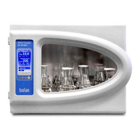
Biosan ES-20/80C User manual

Biosan

Biosan ES-20/80C User manual

Biosan TS-100 User manual

Biosan

Biosan TS-100 User manual

Biosan Microspin FV-2400 User manual

Biosan

Biosan Microspin FV-2400 User manual
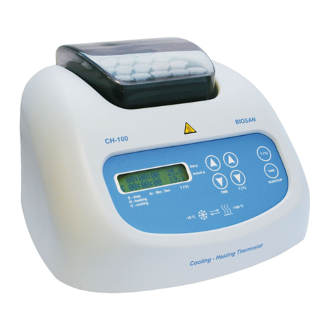
Biosan CH-100 User manual

Biosan

Biosan CH-100 User manual

Biosan PSU-10i User manual

Biosan

Biosan PSU-10i User manual

Biosan Bio RS-24 User manual

Biosan

Biosan Bio RS-24 User manual

Biosan Automatic Luminescence Analyser ALA1/4 User manual

Biosan

Biosan Automatic Luminescence Analyser ALA1/4 User manual

Biosan MMS-3000 User manual

Biosan

Biosan MMS-3000 User manual

Biosan MMS-3000 User manual

Biosan

Biosan MMS-3000 User manual

Biosan UVR-M User manual

Biosan

Biosan UVR-M User manual

Biosan UVC-AR User manual

Biosan

Biosan UVC-AR User manual

Biosan OD Plate User manual

Biosan

Biosan OD Plate User manual

Biosan FTA-1 User manual

Biosan

Biosan FTA-1 User manual

Biosan RTS-1C User manual

Biosan

Biosan RTS-1C User manual

Biosan BioMagPure 12 Plus User manual

Biosan

Biosan BioMagPure 12 Plus User manual
Biosan S-Bt User manual

Biosan

Biosan S-Bt User manual

Biosan Bio RS-24 User manual

Biosan

Biosan Bio RS-24 User manual

Biosan WB-4MS User manual

Biosan

Biosan WB-4MS User manual

Biosan RCP-24 User manual

Biosan

Biosan RCP-24 User manual
Biosan DEN-1 User manual

Biosan

Biosan DEN-1 User manual

Biosan DEN-1B User manual

Biosan

Biosan DEN-1B User manual

Biosan Multi Bio 3D User manual

Biosan

Biosan Multi Bio 3D User manual

Biosan UVT-B-AR User manual

Biosan

Biosan UVT-B-AR User manual

Biosan Sunflower Mini-Shaker 3D User manual

Biosan

Biosan Sunflower Mini-Shaker 3D User manual

Popular Laboratory Equipment manuals by other brands

Selecta VACIOTEM-T manual

Selecta

Selecta VACIOTEM-T manual

Beckman Coulter JA-25.50 Instructions for use

Beckman Coulter

Beckman Coulter JA-25.50 Instructions for use

cytiva AKTA flux 6 operating instructions

cytiva

cytiva AKTA flux 6 operating instructions

Emtek R100 user manual

Emtek

Emtek R100 user manual

Izon AFC V2 quick start guide

Izon

Izon AFC V2 quick start guide

Plasmapp STERLINK U-510 user manual

Plasmapp

Plasmapp STERLINK U-510 user manual

WPI MSI-150 instruction manual

WPI

WPI MSI-150 instruction manual

XD COLLECTION P301.10X manual

XD COLLECTION

XD COLLECTION P301.10X manual

Julabo MAGIO MS-310F operating manual

Julabo

Julabo MAGIO MS-310F operating manual

Beckman Coulter SX4750A Instruction for use, installation and assembly

Beckman Coulter

Beckman Coulter SX4750A Instruction for use, installation and assembly

Steris Reliance 1024 Uncrating/Installation Instructions

Steris

Steris Reliance 1024 Uncrating/Installation Instructions

Fisher Scientific Fisherbrand accuSpin Micro Series instruction manual

Fisher Scientific

Fisher Scientific Fisherbrand accuSpin Micro Series instruction manual

Labnet 25 operating instructions

Labnet

Labnet 25 operating instructions

Labconco Purifier 3951400 user manual

Labconco

Labconco Purifier 3951400 user manual

DIGISYSTEM DSD-100D instruction manual

DIGISYSTEM

DIGISYSTEM DSD-100D instruction manual

Buchi Process Analyser X-One Operation manual

Buchi

Buchi Process Analyser X-One Operation manual

Telemark Cryogenics 1200 instruction manual

Telemark Cryogenics

Telemark Cryogenics 1200 instruction manual

Antec Scientific ROXY Exceed user manual

Antec Scientific

Antec Scientific ROXY Exceed user manual

manuals.online logo
manuals.online logoBrands
  • About & Mission
  • Contact us
  • Privacy Policy
  • Terms and Conditions

Copyright 2025 Manuals.Online. All Rights Reserved.