(a) Installation sheet .........................................................1
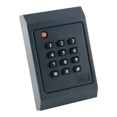
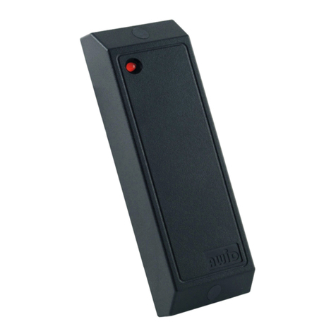
(b) MR-1824 Reader ........................................................2
(c) #6-20 x 1.375” self-ta ing screw .............................. 8
(d) Plastic anchor ............................................................. 8
(e) Screw-hole lug......................................... 10 (2 s are)
(f) Cable slot lug............................................................ 4
Installation Procedure for Each Reader
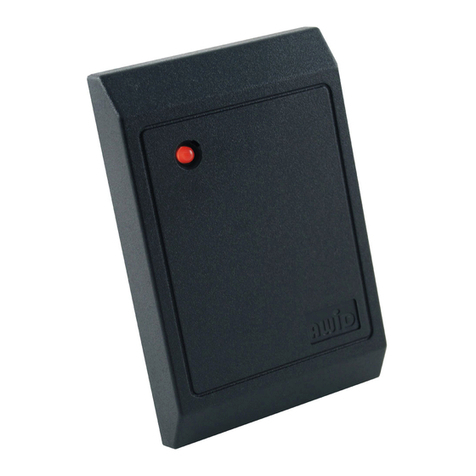
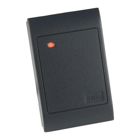
1. Position the first reader (item b in the Parts List) at the desired location. Observe ADA height
requirements. Drill 4 holes for the screws or anchors, and drill 1 clearance hole for the cable (see Figure 1).
The installer determines the size of mounting holes and cable clearance hole.
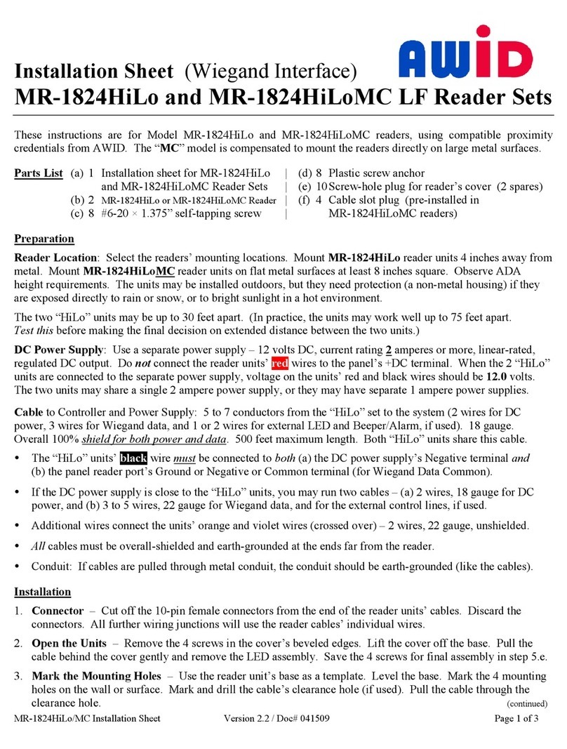
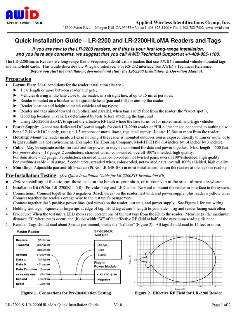
2. Cli off the white inline connector from the end of the reader’s cable. Kee the wires as long as ossible.
3. Use a linear regulated DC ower su ly, between 5 volts (current rating 800 milliam eres or more)
and 12.0 volts maximum (current rating 2 am eres or more) for the combined readers. Do not power
the MR-1824HiLo from the reader ort’s DC voltage terminals on the anel – use a se arate DC ower
su ly. (For guaranteed erformance, AWID offers P/N PS-123.3A ower module.) Tie the ground side
of all DC circuits together – including both MR-1824 readers, the anel’s reader in ut ort, the se arate
DC ower su ly, and the door lock or gate motor contacts.
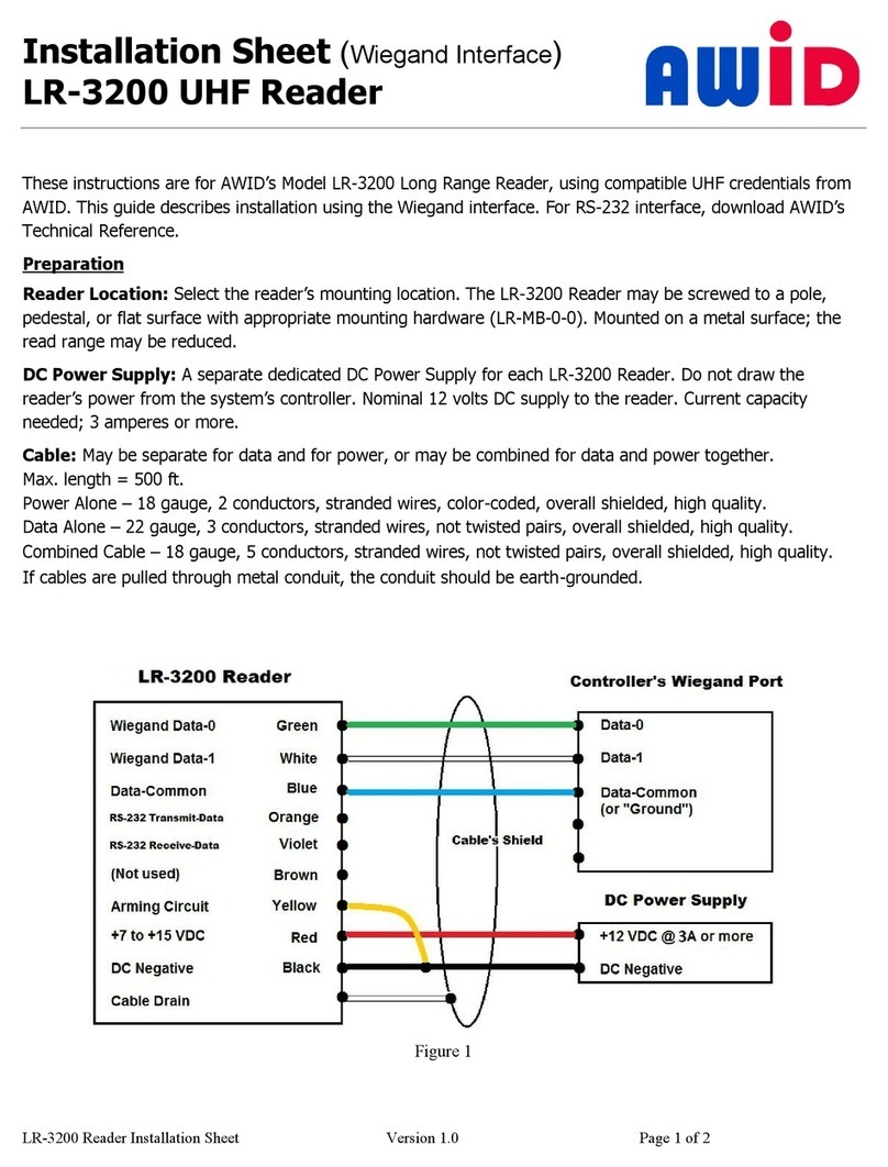
4. Connect the reader’s wires for ground, data-0, data-1, LED and ower, and the silver drain wire (see Fig. 2).
Connect the yellow wire only if used for Bee er control by the anel. Connect the orange and violet wires
to the o osite colors (violet and orange) on the other reader of the set. Do not connect the blue wire.
Tape or cap the unused wires se arately. The MR-1824HiLo set uses a single Wiegand in ut on the anel.
5. To install the reader’s cable through the wall directly behind the reader, insert both cable slot lugs
(item f in the Parts List) in the sides of the reader’s to cover. To run the cable exiting from the side of the
reader, ress the cable into the curved channel and guide the cable out of the desired side of the reader.
Then insert the cable slot lug in the other side of the to cover. Extend the cable straight away from
the reader housing as far as ossible.
6. Install the reader on the mounting surface, using screws (item c in the Parts List) and anchors (item d)
as necessary.
7. Re eat ste s 1 through 6 for the second reader of the MR-1824HiLo set. Readers may be u to 75 ft a art.
8. A ly DC ower to both readers. The LED is steady amber. (The bee er does not sound.)
9.
Present any AWID roximity credential (card, keytag or wafer) briefly to the reader. The bee er sounds a
single Long bee . The LED is steady red to indicate Standby mode. The reader is now initialized and can
read cards. Note: All credentials must be AWID’s roducts. Other com anies’ cards and tags will not read.
10. The LED color in Standby mode may be changed from red to green, or from green to red, using a
Color Changer card, available from AWID. Remove ower from the reader for a few seconds, and then
restore ower. While the LED is amber, resent the Color Changer card to toggle the LED color at Standby.
When the LED color changes, remove the card.
11. When installation is com lete and the readers have been tested, insert screw-hole lugs (item e in
the Parts List) into the screw clearance holes to conceal the screw heads. Note: Screw-hole lugs are
for one-time use. After they are seated, they cannot be removed without damaging the lugs.
