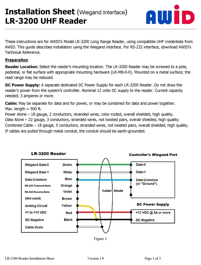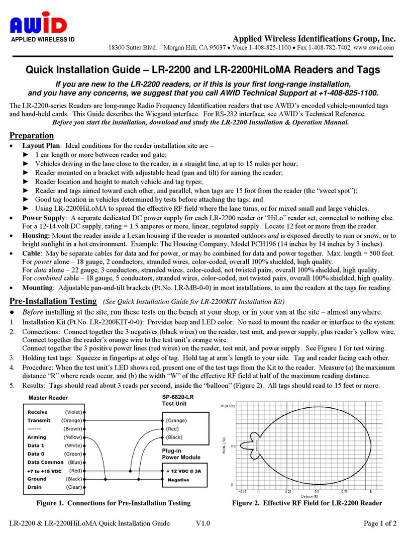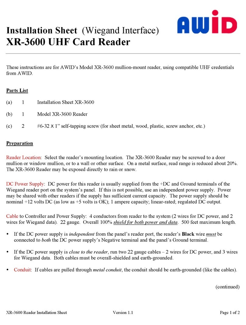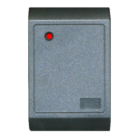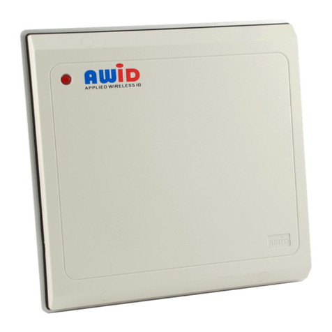
SR-2400 Reader Installation Sheet
Installation Sheet
SR-2400 Low-
These instructions are for AWID’s SR-
Parts List
(a) 1 Installation Sheet for SR-2400
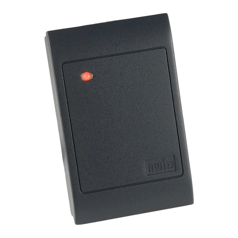
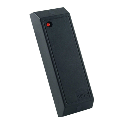
( ) 1 Model SR-2400 Reader
(c) 2 #6-32 × 1” thread-cutting screw
(d) 3 Screw-hole plug (1 spare)
Preparation
Reader Location
: Select the reader’s mounting location. The
1-3/4 inch door frame
, or to a wall or other surface. On a metal surface, read range is reduced a out 20%.
The SR-2400 may e installed indoo
DC Power Supply:
DC power for this reader is usually supplied from the +DC and Ground terminals of the
Wiegand reader port on the system’s panel. If this is not possi le, use a
shared with other readers if the supply has sufficient c
volts DC (as low as +5 volts is OK),
Cable
to Controller and Power Supply: 4 to
2 wires for Wiegand data, and 1 or 2
wires. Overall 100%
shield for both power and data
If the DC power supply is separated from the panel’s reader port, the reader’s
connected to both
the DC power supply’s Negative terminal and the panel reader port’s Ground terminal.
If the separate DC power supply is close to the reader, run two 22
and 3 to 5
wires for Wiegand data (including Ground) and for the external control lines, if used.
Both ca les must e overall-
Conduit: If ca les are pulled through metal conduit, the conduit should e earth
Installation
1. Connector – Cut off the 10-pin in-
line connector from the end of the reader’s ca le. D
2. ire Connections –
Connect the reader’s wires to the ca le(s) for power and data.
a. First, connect black
to the panel port’s Ground terminal, and, if separate, to the power supply Negative.
. Connect green to the Data-
c. Connect the gray
drain wire to the shield of the connecting ca le.
If power and data are in separate ca les, connect all three drains/shields together near the reader.
d. If the LED and/or Beeper/Alarm
features are used, connect the
e.
At the end of the ca le(s) near the panel (and near the power supply, if separate), connect the
verified earth-ground.
f. Last, connect red
to the DC Positive terminal.
Version 2 / Doc# 041405
R
eader, using compati le proximity credentials
: Select the reader’s mounting location. The
SR-2400
Reader may e screwed to a
, or to a wall or other surface. On a metal surface, read range is reduced a out 20%.
.
The diagram for screw and ca le holes is on page 2.
DC power for this reader is usually supplied from the +DC and Ground terminals of the
Wiegand reader port on the system’s panel. If this is not possi le, use a
separate
power supply. Power may e
shared with other readers if the supply has sufficient c
urrent capacity. The power supply should e close to +12
amperes capacity, linear-
rated, regulated DC output.
to Controller and Power Supply: 4 to
6
conductors from the reader to the system (2 wires fo
and Beeper/Alarm, if used).
shield for both power and data
. 500 feet maximum length.
If the DC power supply is separated from the panel’s reader port, the reader’s
black
the DC power supply’s Negative terminal and the panel reader port’s Ground terminal.
If the separate DC power supply is close to the reader, run two 22
-gauge ca les –
wires for Wiegand data (including Ground) and for the external control lines, if used.
-gr
ounded (at the end far from the reader).
Conduit: If ca les are pulled through metal conduit, the conduit should e earth
-
grounded (like the ca les).
line connector from the end of the reader’s ca le. D
Connect the reader’s wires to the ca le(s) for power and data.
to the panel port’s Ground terminal, and, if separate, to the power supply Negative.
. Connect white to the Data-1 terminal.
drain wire to the shield of the connecting ca le.
If power and data are in separate ca les, connect all three drains/shields together near the reader.
features are used, connect the
brown and/or
At the end of the ca le(s) near the panel (and near the power supply, if separate), connect the
to the DC Positive terminal.
Page 1 of 2
eader, using compati le proximity credentials
from AWID.
Reader may e screwed to a
, or to a wall or other surface. On a metal surface, read range is reduced a out 20%.
The diagram for screw and ca le holes is on page 2.
DC power for this reader is usually supplied from the +DC and Ground terminals of the
power supply. Power may e
urrent capacity. The power supply should e close to +12
rated, regulated DC output.
conductors from the reader to the system (2 wires fo
r DC power,
22-gauge stranded
must e
the DC power supply’s Negative terminal and the panel reader port’s Ground terminal.
wires for Wiegand data (including Ground) and for the external control lines, if used.
ounded (at the end far from the reader).
grounded (like the ca les).
line connector from the end of the reader’s ca le. D
iscard the connector.
to the panel port’s Ground terminal, and, if separate, to the power supply Negative.
If power and data are in separate ca les, connect all three drains/shields together near the reader.
wires.
At the end of the ca le(s) near the panel (and near the power supply, if separate), connect the
shield to a
(continued)
