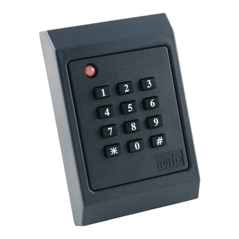
AWID UA-612 Assembly instructions
Other AWID Card Reader manuals
AWID
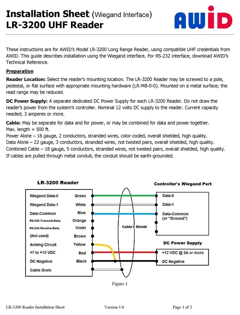
AWID LR-3200 Assembly instructions
AWID
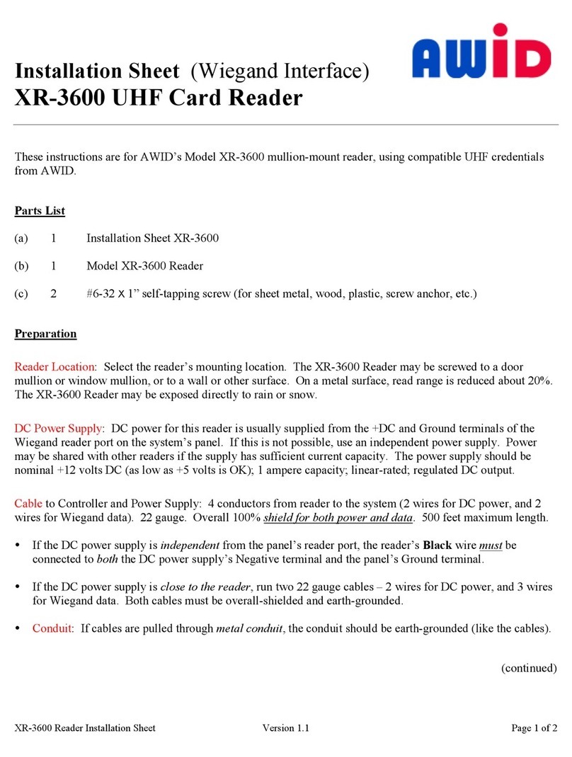
AWID XR-3600 Assembly instructions
AWID
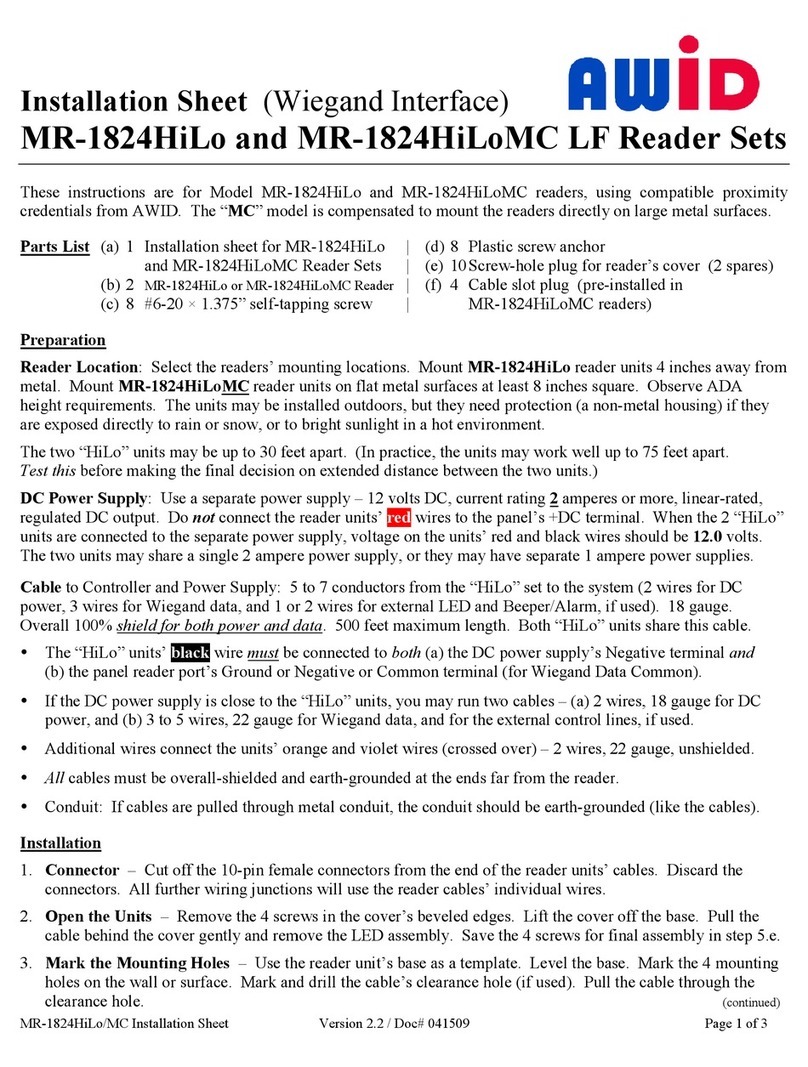
AWID MR-1824HiLo Assembly instructions
AWID
AWID Sentinel-Prox MR-1824HiLo Assembly instructions
AWID
AWID SR-2400 Assembly instructions
AWID
AWID SENTINEL-PROX LR-911 User manual
AWID
AWID SP-6820 Assembly instructions

AWID
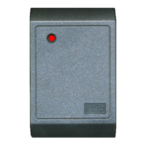
AWID uAxcess XJ-1023 User manual
AWID
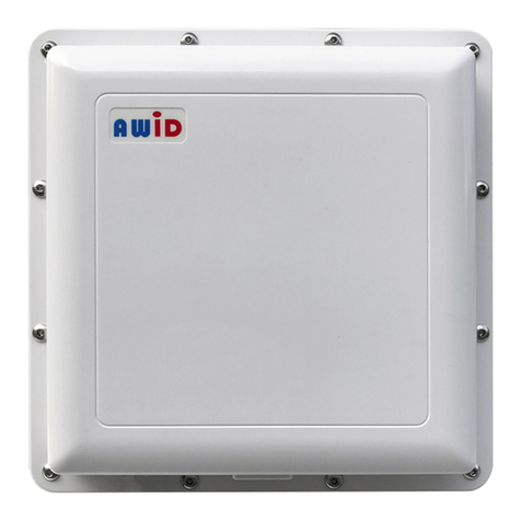
AWID SENTINEL-PROX SC-2300 User manual
AWID
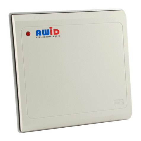
AWID LR-3000 User manual
AWID
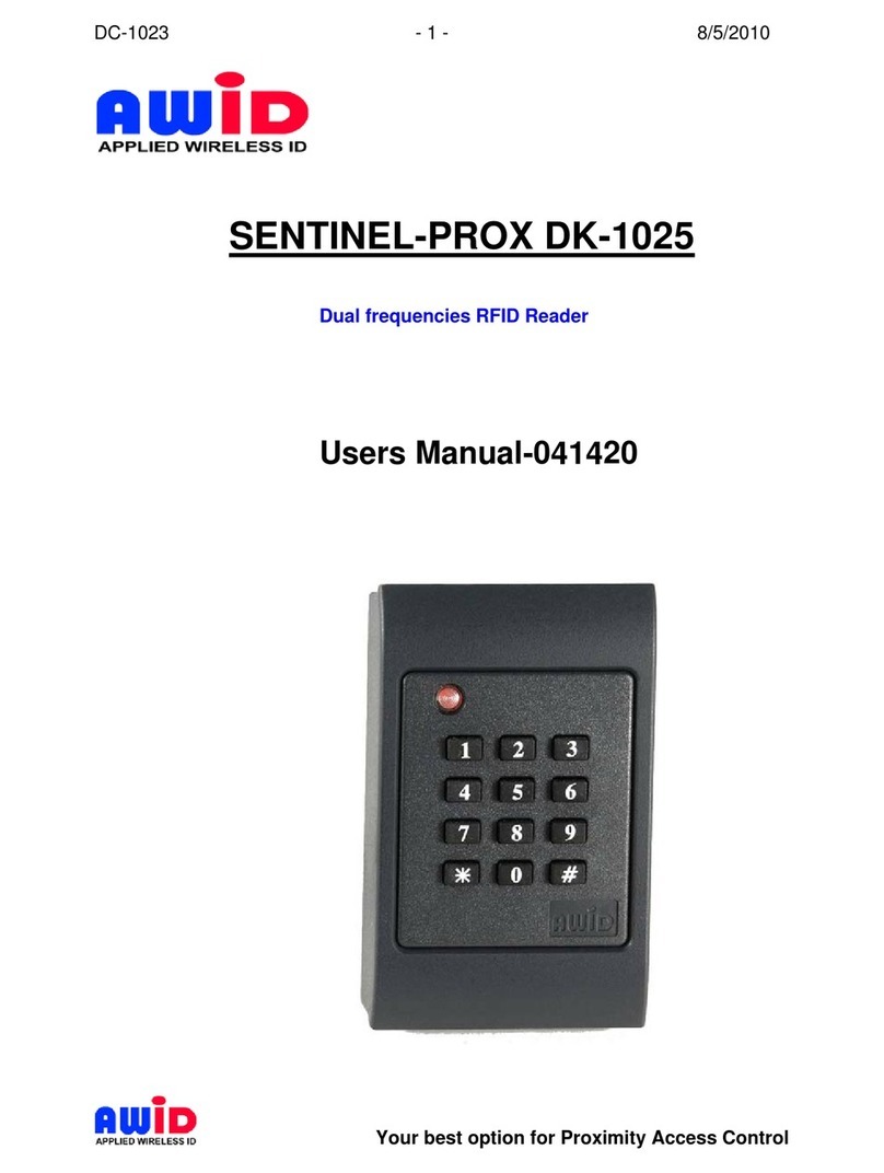
AWID SENTINEL-PROX LR-2000 User manual
AWID
AWID SENTINEL-PROX DK-1025 User manual
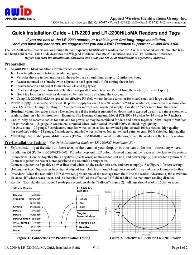
AWID
AWID LR-2200 User manual
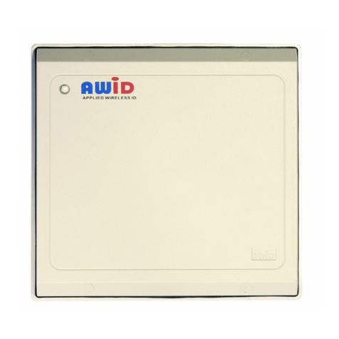
AWID
AWID SENTINEL-PROX LR-911 User manual
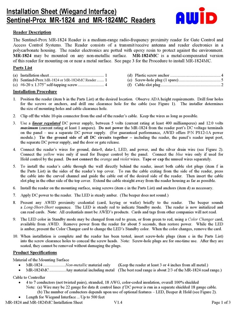
AWID
AWID SENTINEL-PROX MR-1824 Assembly instructions
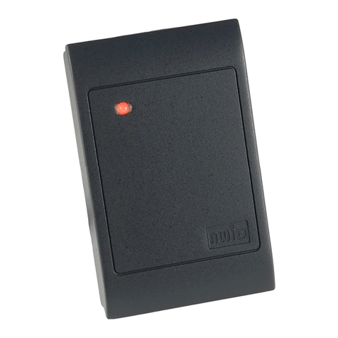
AWID
AWID Sentinel-Prox DC-1023 Assembly instructions
AWID
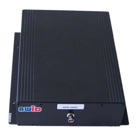
AWID MPR-5005 User manual
AWID
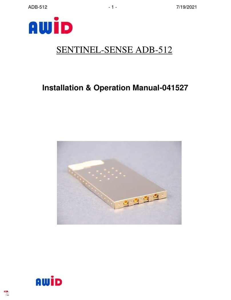
AWID Sentinel-Sense ADB-512 User manual
AWID
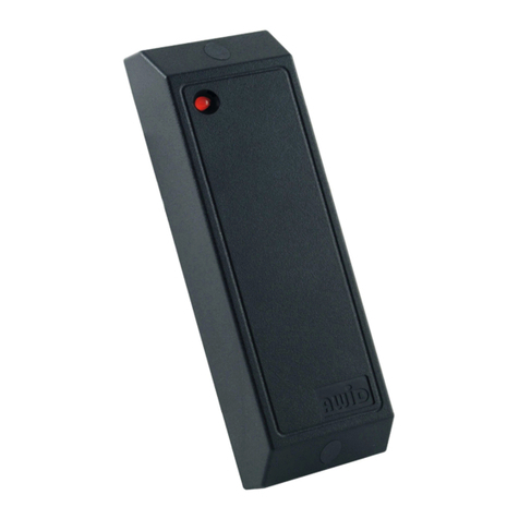
AWID MM-6800 Assembly instructions
AWID
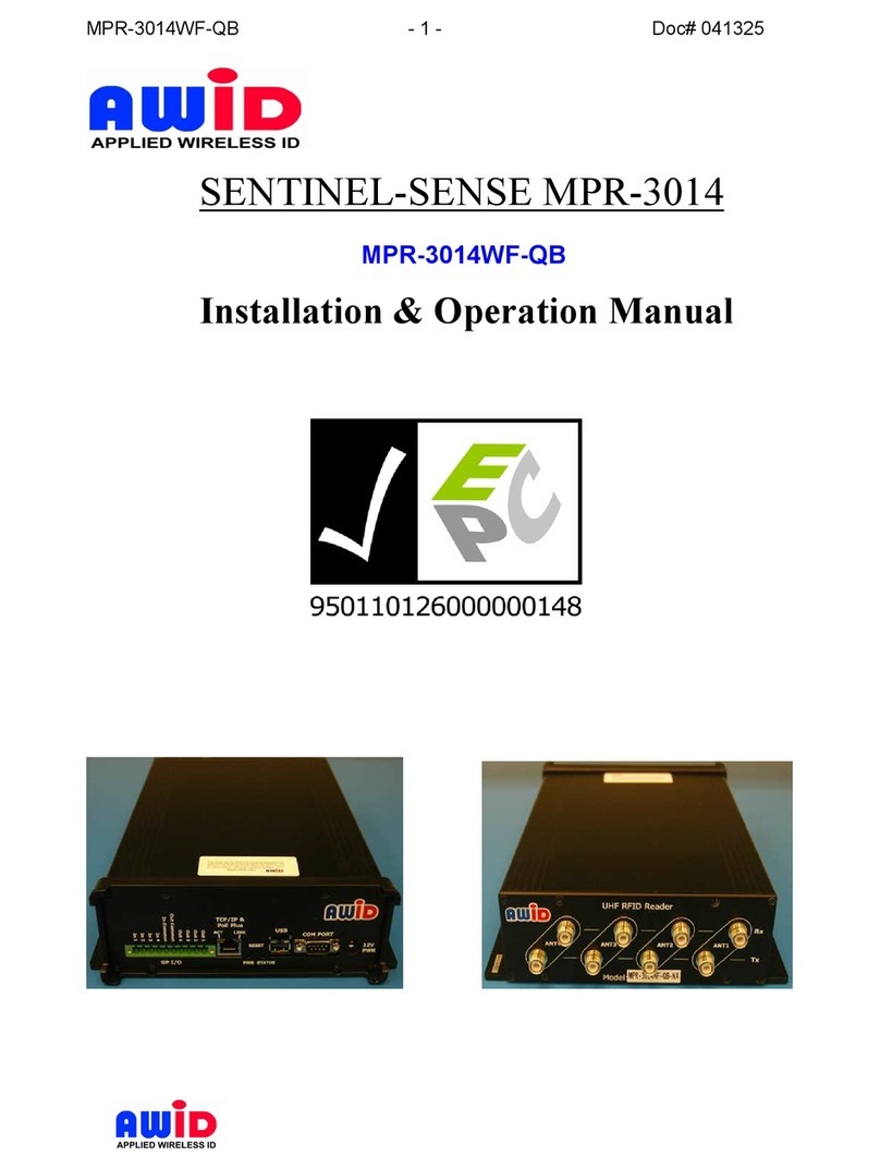
AWID MPR-3014WF-QB User manual
Popular Card Reader manuals by other brands

ViziT
ViziT RD-4F operating instructions

Jinmuyu Electronics
Jinmuyu Electronics MR811 Series user manual

Conrad
Conrad PCMCIA operating instructions

Lindy
Lindy 51541 user manual

Diapro T?bbi Ürünler
Diapro T?bbi Ürünler Across System user manual

Johnson Controls
Johnson Controls Kantech tyco ioSmart installation guide

