XK-3640 Reader Installation Sheet Version 1.1 Page 1 of 2
Installation Sheet (Wiegand Interfa e)
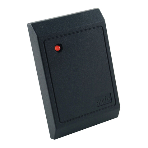
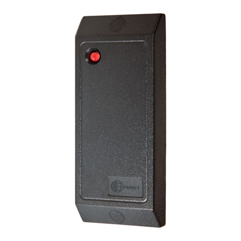
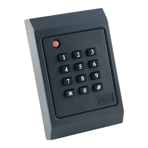
XK-3640 UHF Card & PIN Reader
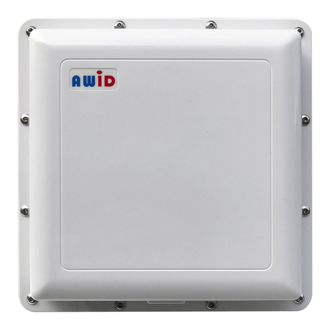
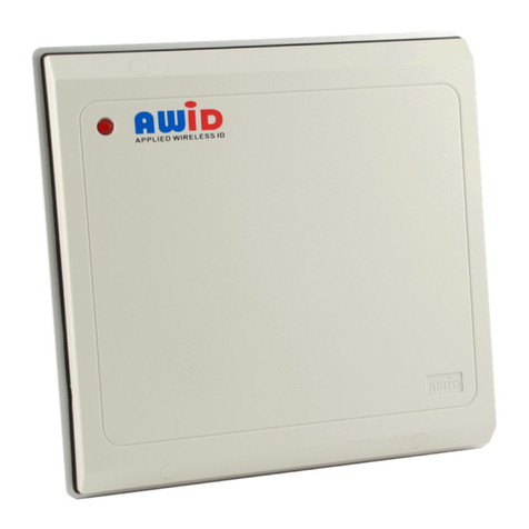
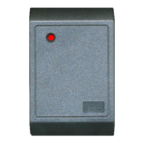
These instru tions are for AWID’s Model XK-3640 reader, using ompatible UHF redentials from AWID.
Parts List | (b) 1 Model XK-3640 Reader/Keypad
(a) 1 Installation Sheet for XK-3640 | ( ) 2 #6-32 × 1” ma hine s rew (for single-gang utility box)
Pre aration
Reader Lo ation: Sele t the reader’s mounting lo ation. The XK-3640 Reader may be s rewed to a single-
gang utility box like a over plate, or to a wall or other surfa e. On a metal surfa e, read range is redu ed about
20%. The XK-3640 Reader may be installed indoors or outdoors, but needs prote tion from dire t rain or snow.
DC Power Supply: DC power for this reader is usually supplied from the +DC and Ground terminals of the
Wiegand reader port on the system’s panel. If this is not possible, use an independent power supply. Power
may be shared with other readers if the supply has suffi ient urrent apa ity. The power supply should be
nominal +12 volts DC (as low as +5 volts is OK); 1 ampere apa ity; linear-rated; regulated DC output.
Cable to Controller and Power Supply: 4 ondu tors from reader to the system (2 wires for DC power, and 2
wires for Wiegand data). 22 gauge. Overall 100% shield for both power and data. 500 feet maximum length.
If the DC power supply is independent from the panel’s reader port, the reader’s Black wire must be
onne ted to both the DC power supply’s Negative terminal and the panel’s Ground terminal.
If the DC power supply is lose to the reader, run two 22 gauge ables – 2 wires for DC power, and 3 wires
for Wiegand data. Both ables must be overall-shielded and earth-grounded.
Conduit: If ables are pulled through metal onduit, the onduit should be earth-grounded (like the ables).
Programming
The XK-3640 reader is shipped with the keypad’s output set for buffered 26-bit output, and its fa ility (site)
ode set at 000. These two features an be programmed at your shop before you go to the installation site. Just
onne t DC power from a ben h supply or from a 9 volt or 12 volt battery to the red and black wires.
Start either programming routine with DC removed from the XK-3640 unit. Keep the unit fully assembled.
Key ad’s Out ut Format
1. While the DC power is dis onne ted . . . press and hold the 4 key if format is to be 4-bit data burst;
or hold the 8 key for 8-bit data burst, or hold the 2 key for 26-bit buffered data.
2. With the 4 or 8 or 2 key still pressed in, onne t the DC power. Within 3 se onds there is a beep
sequen e, and the LED hanges to standby-red.
3. Now release the pressed key. The hange in keypad output format has been saved.
Facility Code in Key ad’s 26-bit Buffered Out ut
1. Conne t the DC power. Wat h the unit’s LED. While it is amber, slowly enter the 10-digit password
9 1 4 3 6 9 8 8 0 0; end with #. Press ea h key solidly. There is a short beep during ea h keystroke.
2. Within 3 se onds, enter the fa ility ode’s 3 digits (between 000 and 255); end with #.
3. There is a long beep and the LED olor hanges to standby-red. The fa ility ode has been saved.
Programming an be done also on an installed XK-3640. The keypad’s format an be hanged anytime to any
of the three formats, and the 26-bit’s facility code an be hanged to any value between de imal 000 and 255.
Programming for O eration Mode (mix of ard read and/or PIN) is done only in the host system’s software.
