Innovator CU10BT-CU5000BT Analog Transmitter Table of Contents
Instruction Manual, Rev. 0 i /28/11
Table of Contents
Introduction 1
Manual Overview ............................................................................................1
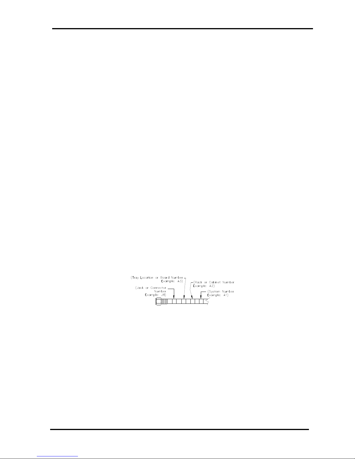
Assembly Designation Numbers........................................................................1
Safety ...........................................................................................................1
Contact Information........................................................................................2
Return Material Procedure ...............................................................................
Limited One Year Warranty for Axcera Products..................................................
System Description 11
Unpacking, Installation and Maintenance 13
Unpacking ...................................................................................................1
Installation ..................................................................................................1
Drawer Slide Installation 14
AC Input Connections 15
Input and Output Connections 16
Maintenance ................................................................................................18
Initial On Site Turn On Procedure 19
Typical System Operating Parameters 20
Typical Problems, Indications and Causes 21
LCD Display and Front Panel LED Indicators 21
System Remote Connections 23
LCD Front Panel Screens 25
Operation Screens ........................................................................................26
Set Up Screens ............................................................................................ 1
(Optional) Innovator CX Series Web Ethernet Interface Kit (1313100) 37
(Optional) Innovator CXB Series SNMP Ethernet Interface (1313079) 42
Circuit Descriptions of Boards in the CU10, CU60, CU100 & CU200 Systems 43
(A1) Analog Modulator Board, System M/N (1 12264) ......................................4
(A ) IF Pre-Corrector Board (1 08796) ...........................................................44
Pin-Diode Attenuator Circuit 44
In Phase and Quadrature Corrector Circuits 45
Frequency Response Corrector Circuit 46
ALC Circuit 46
Input Fault and Modulation Fault Circuitry 47
±12 VDC, +6 8 VDC, and VREF needed to operate the Board 47
(A4) Frequency Agile Upconverter Board (1 09695) .........................................48
(A5) ALC Board, Innovator CX Series (1 08570) ..............................................49
(A6) Amplifier Assembly (1 09621) – Used in the CU5BT ..................................51
(A6-A1) 2 Stage UHF Amplifier Board, 24V (1309608) 51
(A6) Amplifier Assembly (1 12566) – Used in the CU60BT and CU100BT ............52
(A6-A1) 2 Stage UHF Amplifier Board (1308784) 52
(A6-A2) RF Module Pallet, Philips, High Output (1309580) 52
(A6) Amplifier Assembly (1 12191) – Used in the CU200BT...............................5
(A6-A1) 1 Watt UHF Amplifier Module (1310282) 53
(A6-A2) BL871 Single Stage Amplifier Board (1311041) 53
(A6-A3) Dual 878 Pallet Assembly (1310138) 53
Or (A6) Amplifier Assembly (1 15 81) – Used in the CU200BT. .........................5
(A6-A1) 1 Watt UHF Amplifier Module (1310282) 54
(A6-A2) BLF881 Single Stage Amplifier Board (1314882) 54
(A6-A3) Dual BLF888A Pallet Assembly (1315347) 54
(A6-A5) DC/DC Converter Board (1315335) 54
(A7) Output Detector Board (1 12207) ...........................................................55
(A8) Control Card, Innovator CX (1 1254 ).....................................................55