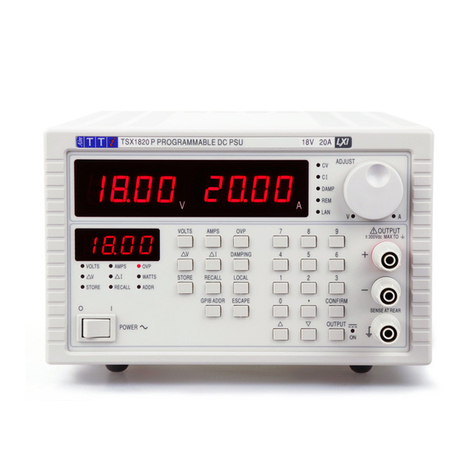
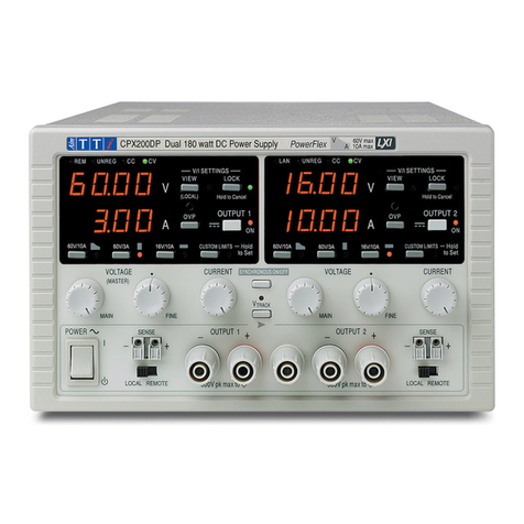
TTI PL154 User manual

THURLBY THANDAR INSTRUMENTS
PRECISION LINEAR POWER SUPPLIES
PL SERIES
INSTRUCTION MANUAL

Table of Contents
Specification 2
Safety 4
EMC 6
Installation 7
Connections 8
Operation 9
Maintenance 12
Instructions en Francais
Sécurité 13
Installation 14
Fonctionnement 16
Entretien 19
Bedienungsanleitung auf Deutsch
Sicherheit 20
Installation 21
Betrieb 23
Wartung 27
1

Specification
MAIN OUTPUT(S)
Output Range: Nominally 0-32V, (PL320/330); 0-15.5V (PL154).
Nominally 0-2·1A (PL320); 0-3·1A (PL330); 0-4A (PL154).
Output Voltage Setting: By coarse and fine controls; resolution <5mV across the range.
Output Current Setting: By single logarithmic control.
Output Mode: Constant voltage or constant current modes with automatic cross-over.
Decimal points flash to indicate constant current mode.
Configuration Selection:
(QMD and QMT only)
Isolated, True parallel, Series, or Series Tracking via front panel switches.
Output Switch: Isolates the output and permits voltage and current limits to be set up before
connecting the load.
Output Terminals: 4mm terminals on 19mm (0·75") spacing.
Sensing: Remote via 4mm terminals or direct via shorting links (provided).
Output Impedance:
Constant Voltage:
Constant Current:
<5 mΩat 1kHz.
Typically 50 kΩ with voltage limit at maximum.
Output Protection: Up to maximum output voltage +20 Volts forward; diode clamped for reverse
voltages and up to 3A reverse current.
Load & Line Regulation: < 0·01% of maximum output for 90% load change or 10% line change.
Ripple and Noise: Typically <1 mV rms.
Transient Response: < 20 µsec to within 50 mV of setting for 90% load change.
Temperature Coefficient: Typically < 100 ppm/OC.
Meter Type: Dual 3·75 digit (4095 count) with 12·5mm (0·5") LEDs. Reading rate 4Hz.
Meter Resolution: 10 mV and 1mA over the entire range.
Meter Accuracy: Voltage 0·1% of reading + 1 digit, current 0·3% of reading + 1 digit.
Current Meter Damping: ~20 ms, switchable to 2 sec for averaging of rapidly varying loads.
LOGIC OUTPUT (PL320QMT & PL330QMT)
Output Voltage Range: 4 to 6 Volts.
Output Current: 0·1 to 4 Amps (PL320QMT); 0·1 to 7 Amps (PL330QMT).
Output Switch: Electronic.
Output Terminals: 4mm terminals on 19mm (0·75") spacing.
Over-Voltage Protection: Above 7 Volts.
Output Protection: Clamped by the over-voltage protection circuit for forward voltages over
7 Volts and up to 1 Amp forward current. Diode clamped for reverse voltages
and up to 3 Amps reverse current.
Load & Line Regulation: < 0·01% of maximum output for 90% load change or 10% line change.
Ripple and Noise: Typically <1 mV rms.
2

Transient Response: < 20 µsec to within 50 mV of setting for 90% load change.
Temperature Coefficient: Typically < 100 ppm/oC.
Metering (PL330QMT
only):
Meter Type:
3·75 digit (4095 count) with 12·5mm (0·5") LEDs. Reading rate 4Hz.
Meter Resolution:
Meter Accuracy:
10 mV and 10 mA
0·5% of reading + 1 digit.
GENERAL
AC Input Voltage: Internally set for 110, 120, 220, 230 or 240VAC 50/60 Hz; operating range
±10% of setting. Installation Category II.
Power Consumption: Single Dual Triple
15V / 4A or 30V / 2A: 160VA 320VA 400VA
30V / 3A: 250VA 500VA 600VA
Operating Range: 5OC to 40 OC, 20% to 80% RH.
Storage Range: -20 OC to +60 OC.
Environmental: Indoor use at altitudes up to 2000m, Pollution Degree 2.
Weight: Single Dual Triple
15V / 4A or 30V / 2A: 5.0kg 9.5kg 12.5kg
30V / 3A: 6.0kg 12.0kg 15.0kg
Size: Single Dual Triple.
155 mm wide 350 mm wide 425 mm wide
All units 170mm high and 265mm deep, except PL330 versions 300mm
deep.
Safety: Complies with EN61010-1.
EMC: Complies with EN61326.
3

Safety
This instrument is Safety Class I according to IEC classification and has been designed to meet
the requirements of EN61010-1 (Safety Requirements for Electrical Equipment for Measurement,
Control and Laboratory Use). It is an Installation Category II instrument intended for operation
from a normal single phase supply.
This instrument has been tested in accordance with EN61010-1 and has been supplied in a safe
condition. This instruction manual contains some information and warnings which have to be
followed by the user to ensure safe operation and to retain the instrument in a safe condition.
This instrument has been designed for indoor use in a Pollution Degree 2 environment in the
temperature range 5°C to 40°C, 20% - 80% RH (non-condensing). It may occasionally be
subjected to temperatures between +5°C and –10°C without degradation of its safety. Do not
operate while condensation is present.
Use of this instrument in a manner not specified by these instructions may impair the safety
protection provided. Do not operate the instrument outside its rated supply voltages or
environmental range.
WARNING! THIS INSTRUMENT MUST BE EARTHED
Any interruption of the mains earth conductor inside or outside the instrument will make the
instrument dangerous. Intentional interruption is prohibited. The protective action must not be
negated by the use of an extension cord without a protective conductor.
When the instrument is connected to its supply, terminals may be live and opening the covers or
removal of parts (except those to which access can be gained by hand) is likely to expose live
parts. The apparatus shall be disconnected from all voltage sources before it is opened for any
adjustment, replacement, maintenance or repair. Capacitors inside the power supply may still be
charged even if the power supply has been disconnected from all voltage sources but will be
safely discharged about 1 minute after switching off power.
Any adjustment, maintenance and repair of the opened instrument under voltage shall be avoided
as far as possible and, if inevitable, shall be carried out only by a skilled person who is aware of
the hazard involved.
If the instrument is clearly defective, has been subject to mechanical damage, excessive moisture
or chemical corrosion the safety protection may be impaired and the apparatus should be
withdrawn from use and returned for checking and repair.
Make sure that only fuses with the required rated current and of the specified type are used for
replacement. The use of makeshift fuses and the short-circuiting of fuse holders is prohibited.
Do not wet the instrument when cleaning it.
The following symbols are used on the instrument and in this manual:-
Earth (ground) terminal.
alternating current (ac)
direct current (dc)
4

EC Declaration of Conformity
We Thurlby Thandar Instruments Ltd
Glebe Road
Huntingdon
Cambridgeshire PE29 7DR
England
declare that the following power supplies:
PL154, PL320, PL320QMD, PL320QMT, PL330, PL330QMD, PL330QMT
meet the intent of the EMC Directive 2004/108/EC and the Low Voltage Directive 2006/95/EC.
Compliance was demonstrated by conformance to the following specifications which have been
listed in the Official Journal of the European Communities.
EMC
Emissions: a) EN61326-1 (2006) Radiated, Class B
b) EN61326-1 (2006) Conducted, Class B
c) EN61326-1 (2006) Harmonics, referring to EN61000-3-2 (2006)
Immunity: EN61326-1 (2006) Immunity Table 1, referring to:
a) EN61000-4-2 (1995) Electrostatic Discharge
b) EN61000-4-3 (2006) Electromagnetic Field
c) EN61000-4-11 (2004) Voltage Interrupt
d) EN61000-4-4 (2004) Fast Transient
e) EN61000-4-5 (2006) Surge
f) EN61000-4-6 (2007) Conducted RF
Performance levels achieved are detailed in the user manual.
Safety
EN61010-1 Installation Category II, Pollution Degree 2.
CHRIS WILDING
TECHNICAL DIRECTOR
1 May 2009
5

EMC
This instrument has been designed to meet the requirements of the EMC Directive 2004/108/EC.
Compliance was demonstrated by meeting the test limits of the following standards:
Emissions
EN61326-1 (2006) EMC product standard for Electrical Equipment for Measurement, Control and
Laboratory Use. Test limits used were:
a) Radiated: Class B
b) Conducted: Class B
c) Harmonics: EN61000-3-2 (2006) Class A; the instrument is Class A by product category.
Immunity
EN61326-1 (2006) EMC product standard for Electrical Equipment for Measurement, Control and
Laboratory Use.
Test methods, limits and performance achieved are shown below (requirement shown in
brackets):
a) EN61000-4-2 (1995) Electrostatic Discharge : 4kV air, 4kV contact, Performance A (B).
b) EN61000-4-3 (2006) Electromagnetic Field:
3V/m, 80% AM at 1kHz, 80MHz – 1GHz: Performance A (A) and 1.4GHz to 2GHz:
Performance A (A); 1V/m, 2.0GHz to 2.7GHz: Performance A (A).
c) EN61000-4-11 (2004) Voltage Interrupt: ½ cycle, 0%: Performance A (B);
1 cycle, 0%: Performance B (B); 25 cycles, 70% and 250 cycles, 0%: Performance B (C).
d) EN61000-4-4 (2004) Fast Transient, 1kV peak (AC line), 0·5kV peak (signal connections),
Performance B (B).
e) EN61000-4-5 (2006) Surge, 0·5kV (line to line), 1kV (line to ground), Performance A (B).
f) EN61000-4-6 (2007) Conducted RF, 3V, 80% AM at 1kHz (AC line only; signal
connections <3m, therefore not tested), Performance A (A).
According to EN61326-1 the definitions of performance criteria are:
Performance criterion A: ‘During test normal performance within the specification limits.’
Performance criterion B: ‘During test, temporary degradation, or loss of function or
performance which is self-recovering’.
Performance criterion C: ‘During test, temporary degradation, or loss of function or
performance which requires operator intervention or system reset occurs.’
Cautions
To ensure continued compliance with the EMC directive observe the following precautions:
a) Connect the generator to other equipment using only high quality, double−screened cables.
b) After opening the case for any reason ensure that all signal and ground connections are
remade correctly and that case screws are correctly refitted and tightened.
c) In the event of part replacement becoming necessary, only use components of an identical
type, see the Service Manual.
6

Installation
Mains Operating Voltage
Check that the operating voltage of the instrument shown on the rear panel is suitable for the
local supply. Should it be necessary to change the operating voltage range proceed as follows:
1. Ensure that the instrument is disconnected from the AC supply.
2. Remove the screws holding the case upper and handle.
3. Lift off the case upper.
4. If the transformer primary taps are marked: A 0-110-120 B 0-110-120, rewire as follows:
240V operation: Neutral (blue) wire to A0; Link (red) wire from A120 to B0;
Live (brown) wire to B120.
230V operation: Neutral (blue) wire to A0; Link (red) wire from A110 to B0;
Live (brown) wire to B120.
220V operation: Neutral (blue) wire to A0; Link (red) wire from A110 to B0;
Live (brown) wire to B110.
120V operation: Neutral (blue) wire to A0; Link (blue) wire from A0 to B0;
Link (brown) wire from A120 to B120; Live (brown) wire to B120.
110V operation: Neutral (blue) wire to A0; Link (blue) wire from A0 to B0;
Link (brown) wire from A110 to B110; Live (brown) wire to B110.
Alternatively, if the transformer primary taps are numbered 1 to 6, rewire as follows:
230V operation: Neutral (blue) wire to 6; Link (red) wire from 3 to 4;
Live (brown) wire to 1.
115V operation: Neutral (blue) wire to 6; Link (blue) wire from 3 to 5;
Link (red) wire from 2 to 4; Live (brown) wire to 1.
Note: Units factory set to 220, 230 or 240V will have no blue link wire - this must be provided
when converting to 110/115/120V operation. When converting a 110/115/120V unit to
220/230V/240V the blue link wire should be discarded.
5. Reassemble in the reverse order.
6. Change the fuse type if necessary.
Important Note: Safety regulations state that the AC line voltage to which the apparatus is set
must be clearly marked on the outside. If the line voltage setting is changed, it is imperative that
the voltage marked on the label close to the power lead entry point is also changed.
Fuse
The AC fuse is located on the back panel; note that the PL320QMT and PL330QMT have an
additional AC fuse for their logic output sections. The correct fuse type is 20mm x 5mm 250V
HBC time-lag with the following rating:
Model 220/230/240V 110/115/120V
PL320 / PL154 (single) 1·6A (T) 3.15A (T)
PL330 (single) 2A (T) 4A (T)
PL320QMD / PL320QMT 3.15A (T) 6.3A (T)
PL330QMD 4A (T) 8A (T)
PL330QMT 5A (T) 10A (T)
PL320QMT & PL330QMT Logic 0utput: 1.6A (T) 3.15A (T)
7

Make sure that only fuses with the required rated current and of the specified type are used for
replacement. The use of makeshift fuses and the short-circuiting of fuse holders is prohibited.
Mains Lead
When a three core mains lead with bare ends is provided this should be connected as follows:
BROWN - MAINS LIVE
BLUE - MAINS NEUTRAL
GREEN/YELLOW - EARTH Safety Earth Symbol
As the colours of the wires in the mains lead of this apparatus may not correspond with the
coloured markings identifying the terminals in your plug proceed as follows:
The wire which is coloured green-and-yellow must be connected to the terminal in the plug which
is marked by the letter E or by the safety earth symbol or coloured green or green-and-yellow.
The wire which is coloured blue must be connected to the terminal which is marked with the letter
N or coloured blue or black.
The wire which is coloured brown must be connected to the terminal which is marked with the
letter L or coloured brown or red.
If the unit is to be connected to the main supply by fixed wiring, rather than via an AC line plug,
then the protective earth (ground) wire in the 3 core mains lead shall be connected to a protective
conductor before any other connection is made.
WARNING! THIS APPARATUS MUST BE EARTHED
Any interruption of the mains earth conductor inside or outside the instrument will make the
instrument dangerous. Intentional interruption is prohibited. The protective action must not be
negated by the use of an extension cord without a protective conductor.
Mounting
This instrument is suitable both for bench use and rack mounting. It is delivered with feet for
bench mounting.
Rack kits for mounting supplies in a 19” rack are available from the Manufacturers or their
overseas agents.
Connections
All connections are made from the front panel.
The load(s) should be connected to the positive (red) and negative (black) terminals marked
OUTPUT.
Remote sense connections to the load, if required, are made from the positive (red) and negative
(black) SENSE terminals. The shorting links between OUPTUT and SENSE terminals should be
removed when remote sensing is required. Replace the shorting links (red SENSE to red
OUTPUT, black SENSE to black OUTPUT) when remote sensing is not in use.
The green terminal marked is connected to the chassis and safety earth ground.
8

Operation
Main Outputs
Setting Up the Output
With the power switch ON and the output switch OFF the output voltage and current limit may be
accurately set using the three output controls prior to connection to the load. The left hand meter
indicates voltage and the right hand meter indicates current.
With the output switch in the OFF (set) position, the current meter shows the value of the current
limit setting (indicated by all the decimal points coming on); with the output switch ON, it shows
the value of load current flowing.
Unless remote sensing is required the shorting bars should be placed from + sense to + output
and from - sense to - output. Ensure that the terminals are properly tightened before use.
Constant Voltage
The voltage output is set using the coarse and fine voltage controls; the current control sets the
maximum current that can be supplied.
Constant Current
If the load resistance is low enough such that, at the set level of output voltage, a current greater
than the current limit setting would flow, the supply will automatically move into constant current
operation.
The current output is set using the current limit control; the voltage controls set the maximum
voltage that can be generated.
Constant Current Indication
When the unit is operating in constant current mode, either by intention or because the current
limit point has been reached, the decimal points on the current meter will flash to indicate
constant current rather than constant voltage operation.
Instantaneous Current Output
The current limit control can be set to limit the continuous output current to levels down to 1 mA.
However, in common with all precision bench power supplies, a capacitor is connected across the
output (isolated by the output switch) to maintain stability and good transient response. This
capacitor charges to the output voltage, and short circuiting of the output will produce a short
current pulse as the capacitor discharges which is independent of the current limit setting.
Current Meter Damping
The digital meters have a reading rate of about four readings per second and a damping time
constant of 20 ms, thus providing virtually instantaneous response to reading changes.
If the unit is used to supply a load varying at a rate faster than about 0·5Hz, difficulty may be
experienced in interpreting the current meter readings. This problem can be alleviated by
pressing the button marked DAMPING. This increases the current meter damping time constant
to 2 seconds with the result that the meter will tend to read the average current flowing rather
than following the variations. This facility should only be used when necessary since it greatly
increases settling time and reduces absolute accuracy.
Series or Parallel connection with other units
The output of the power supply unit is fully floating and may be used in series with other power
supply units to generate high DC voltages up to 300V DC.
9

WARNING! Such voltages are exceedingly hazardous and great care should be taken to shield
the output terminals for such use. On no account should the output terminals be touched when
the unit is switched on under such use. All connections to the terminals must be made with the
power switched off on all units.
It should be noted that the unit can only source current and cannot sink it, thus units cannot be
series connected in anti-phase.
The unit can be connected in parallel with others to produce higher currents.Where several units
are connected in parallel, the output voltage will be equal to that of the unit with the highest output
voltage setting until the current drawn exceeds its current limit setting, upon which the output will
fall to that of the next highest setting, and so on. In constant current mode, units can be
connected in parallel to provide a current equal to the sum of the current limit settings.
Application of an external voltage source to the output
In common with all series regulated single-ended power supplies, the unit is not capable of
sinking current provided from an external source.
If a voltage greater than the set output voltage of the unit is applied from an external source, the
internal regulator will turn off, no current will flow, and the voltage meter will read the applied
voltage. No damage will result providing the applied voltage does not exceed the maximum
output voltage of the power supply by more than 20 Volts. Application of a voltage greater than
this is prohibited.
If a reverse voltage is applied, this will be clamped by an internal reverse protection diode. The
reverse current should not exceed 3 Amp.
Additional Instructions for Quad Mode Dual Versions
Quad-Mode Dual versions of the power supplies incorporate a bank of four interlocked push-
button switches which enable any one of four different modes of operation to be selected. These
are as follows:
1. Isolated
Each power supply operates as a completely separate and independent unit, electrically isolated
from the other.
2. Parallel
The output from both units is channelled into the Master unit (right hand side), increasing its
current output capability accordingly. The Master unit then behaves exactly as a single power
supply of increased current capability. The Slave unit (left hand side) becomes inoperative. The
resolution of the current meter is 2mA on the PL330QMD in parallel mode.
3. Series
Operation is as in Isolated mode, except that the Slave positive output terminal is internally
connected to the Master negative output terminal.
4. Tracking
Operation is as for Series mode, except that the Master voltage controls operate on the Master
and Slave units simultaneously. The current limit controls on each unit continue to operate
individually. Tracking accuracy is better than ±0·3% of setting ± 0·1% of full range.
The Slave output switch should always be on. Both outputs are then switched from the Master
output switch.
Remote sensing cannot be used in either Series or Tracking modes, therefore the shorting bars
should be left in place.
10

Additional Instructions for Quad Mode Triple Versions
The Quad-Mode Triple consists of a Quad-Mode Dual as described in the previous section, plus a
logic supply.
P310QMT Logic Supply
This has a fixed 5V 1·5A output which is isolated from the other supplies.
The logic supply is protected against short circuits. It is protected against external forward
voltages up to 16 Volts and reverse voltages by a diode: the reverse current must not exceed 3
Amps.
PL320QMT & PL330QMT Logic Supply
Setting the Output
Set the output with the calibrated control. With the output switch OFF the meter (PL330 only)
displays voltage; with the switch ON it displays load current. Unless remote sensing is required
the shorting bars should be placed from + sense to + output and from - sense to - output.
Current Limit (PL320QMT)
Current limit is indicated by lighting the CURRENT LIMIT LED and is set by a calibrated control
with a range of 0·1A to 4A. The power supply is not designed to operate in constant current mode
as a current source.
Current Limit (PL330QMT)
Current limit is indicated by all the decimal points flashing and is set by a calibrated control with a
range of 0·1A to 7A. The power supply is not designed to operate in constant current mode as a
current source.
Protection
Over-voltage protection is fitted to this supply and will be triggered if the voltage across the output
terminals exceeds 7 Volts. If this occurs the power supply output is crowbared by a thyristor; the
power supply will then shut down and TRIP will be shown in the display. The power supply can be
reset by turning off the DC output switch or by turning the supply off.
The power supply is protected from reverse voltages by a diode; the reverse current must not
exceed 3 Amps.
General
Connection to the Load
The load should be connected to the positive (red) and negative (black) terminals marked
OUTPUT. Both are fully floating and either can be connected to ground. The negative terminals
are permanently connected to the power supply output, whilst the positive ones are switched
electromechanically (main outputs) or electronically (logic outputs). The green terminal is
connected to chassis and to the earth (ground) of the AC input cable.
If the unit is to be used with live measuring or load circuits which have protective earth terminals,
ensure that all protective earth terminals are connected to a protective conductor prior to
switching on (the green front panel terminal may be used for this purpose).
If the unit is to be used with live measuring or load circuits which do not have protective earth
terminals, ensure that the unit AC line plug is inserted before making connections between the
unit output terminals and such circuits.
11

Remote Sensing
The unit has a very low output impedance, but this is inevitably increased by the resistance of the
connecting leads. At high currents, this can result in significant differences between the indicated
source voltage and the actual load voltage, (two 50mΩ connecting leads will drop 0·2V at 2 Amps,
for instance). This problem can be minimised by using short, thick, connecting leads, but where
necessary it can be completely overcome by using the remote sense facility.
This requires the sense terminals to be connected to the output at the load instead of at the
source; remove the two shorting bars and connect the sense terminals directly to the load. To
avoid instability and transient response problems, care must be taken to ensure good coupling
between each output and sense lead. This can be done either by twisting the leads together or by
using coaxially screened cable (sense through the inner). An electrolytic capacitor directly across
the load connection point may also be beneficial.
The voltage drop in each output lead must not exceed 0·5 Volts.
The shorting bars must be re-fitted if the remote sensing facility is not being used. Remote
sensing cannot be used in the tracking or series modes on either output.
Other Considerations
The power supplies generate considerable heat and require a full air cooling flow for correct
operation. Do not obstruct any of the cooling slots in the cover, or block the inflow of air at the
bottom.
Avoid allowing the supply to get damp, and keep away from corrosive fluids.
Maintenance
The Manufacturers or their agents overseas will provide repair for any unit developing a fault.
Where owners wish to undertake their own maintenance work, this should only be done by skilled
personnel in conjunction with the service manual which may be purchased directly from the
Manufacturers or their agents overseas.
Cleaning
If the PSU requires cleaning use a cloth that is only lightly dampened with water or a mild
detergent. Polish the display window with a soft dry cloth.
WARNING! TO AVOID ELECTRIC SHOCK, OR DAMAGE TO THE PSU, NEVER ALLOW
WATER TO GET INSIDE THE CASE. TO AVOID DAMAGE TO THE CASE OR DISPLAY
WINDOW NEVER CLEAN WITH SOLVENTS.
12

Sécurité
Cet instrument est de Classe de sécurité 1 suivant la classification IEC et il a été construit pour
satisfaire aux impératifs EN61010-1 (Impératifs de sécurité pour le matériel électrique en vue de
mesure, commande et utilisation en laboratoire). Il s'agit d'un instrument d'installation Catégorie II
devant être exploité depuis une alimentation monophasée habituelle.
Cet instrument a été soumis à des essais conformément à EN61010-1 et il a été fourni en tout
état de sécurité. Ce manuel d'instructions contient des informations et avertissements qui doivent
être suivis par l'utilisateur afin d'assurer un fonctionnement de toute sécurité et de conserver
l'instrument dans un état de bonne sécurité.
Cet instrument a été conçu pour être utilisé en interne dans un environnement de pollution
Degré 2, plage de températures 5°C à 40°C, 20% - 80% HR (sans condensation). Il peut être
soumis de temps à autre à des températures comprises entre +5°C et –10°C sans dégradation
de sa sécurité. Ne pas l'utiliser lorsqu'il y a de la condensation.
Toute utilisation de cet instrument de manière non spécifiée par ces instructions risque d'affecter
la protection de sécurité conférée. Ne pas utiliser l'instrument à l'extérieur des tensions
d'alimentation nominales ou de la gamme des conditions ambiantes spécifiées.
AVERTISSEMENT! CET INSTRUMENT DOIT ETRE RELIE A LA TERRE
Toute interruption du conducteur de terre secteur à l'intérieur ou à l'extérieur de l'instrument
rendra l'instrument dangereux. Il est absolument interdit d'effectuer une interruption à dessein. Ne
pas utiliser de cordon de prolongation sans conducteur de protection, car ceci annulerait sa
capacité de protection.
Lorsque l'instrument est relié à son alimentation, il est possible que les bornes soient sous
tension et par suite, l'ouverture des couvercles ou la dépose de pièces (à l'exception de celles
auxquelles on peut accéder manuellement) risque de mettre à découvert des pièces sous
tension. Il faut débrancher toute source de tension éventuelle de l'appareil avant de l'ouvrir pour
effectuer des réglages, remplacements, travaux d'entretien ou de réparations. Les condensateurs
qui se trouvent dans le bloc d'alimentation risquent de rester chargés, même si le bloc
d'alimentation a été déconnecté de toutes les sources de tension, mais ils se déchargeront en
toute sécurité environ 1 minute après extinction de l'alimentation.
Eviter dans la mesure du possible d'effectuer des réglages, travaux de réparations ou d'entretien
lorsque l'instrument ouvert est branché à une source d'alimentation, mais si c'est absolument
nécessaire, seul un technicien compétent au courant des risques encourus doit effectuer ce
genre de travaux.
S'il est évident que l'instrument est défectueux, qu'il a été soumis à des dégâts mécaniques, à
une humidité excessive ou à une corrosion chimique, la protection de sécurité sera amoindrie et il
faut retirer l'appareil, afin qu'il ne soit pas utilisé, et le renvoyer en vue de vérifications et de
réparations.
Uniquement remplacer les fusibles par des fusibles d'intensité nominale requise et de type
spécifié. Il est interdit d'utiliser des fusibles bricolés et de court-circuiter des porte-fusibles.
Eviter de mouiller l'instrument lors de son nettoyage.
Les symboles suivants se trouvent sur l'instrument, ainsi que dans ce manuel.
Borne de terre (masse)
courant alternatif (c.a.)
courant continu (c.c.)
13

Installation
Tension d'utilisation secteur
Vérifier que la tension opérationnelle de l'instrument indiquée sur le panneau arrière est
appropriée pour l'alimentation locale. Procéder de la manière ci-dessous pour changer la gamme
de tensions opérationnelles:
1. S'assurer que l'instrument est débranché de l'alimentation c.a.
2. Enlever les vis de retenue de la manette et de la partie supérieure du boîtier.
3. Retirer la partie supérieure du boîtier.
4. Si les prises du primaire du transformateur sont marquées de manière A 0-110-120
B 0-110-120, recâbler de la manière suivante:
Utilisation 240V: Fil neutre (bleu) à A0
relier le fil (rouge) de A120 à B0
fil sous tension (marron) à B120
Utilisation 230V: Fil neutre (bleu) à A0
relier le fil (rouge) de A110 à B0
fil sous tension (marron) à B120
Utilisation 220V: Fil neutre (bleu) à A0
relier le fil (rouge) de A110 à B0
fil sous tension (marron) à B110
Utilisation 120V: Fil neutre (bleu) à A0
relier le fil (bleu) de A0 à B0
relier le fil (marron) de A120 à B120
fil sous tension (marron) à B120
Utilisation 110V: Fil neutre (bleu) à A0
relier le fil (bleu) de A0 à B0
relier le fil (marron) de A110 à B110
fil sous tension (marron) à B110
Autrement, si les prises du primaire du transformateur sont numérotées 1 à 6, recâbler de la
manière suivante:
Utilisation 230V: Fil neutre (bleu) à 6
relier le fil (rouge) de 3 à 4
fil sous tension (marron) à 1
Utilisation 115V: Fil neutre (bleu) à 6
relier le fil (bleu) de 3 à 5
relier le fil (rouge) de 2 à 4
fil sous tension (marron) à 1.
Nota: Les appareils réglés en usine sur 220V/230V ou 240V ne disposent pas de fil de
liaison bleu - ce fil doit être fourni lors de la conversion pour l'exploitation 110/115/220V.
Lors de la conversion d'un appareil 110/115/120V en 220V/230V/240V retirer le fil de
liaison bleu.
5. Effectuer le remontage dans l'ordre inverse.
6. Le cas échéant, changer le type de fusible.
Remarque importante: Les réglementations de sécurité exigent une désignation distincte de la
tension de ligne c.a. à laquelle l'appareil est réglé, ce à la partie externe. En cas de changement
du réglage de la tension de ligne, il est extrêmement important de changer également la tension
marquée sur l'étiquette à proximité du point d'entrée du câble d'alimentation.
14

Fusible
Le fusible c.a. se trouve sur le panneau arrière; il faut noter que le PL320QMT et PL330QMT ont
un fusible c.a. supplémentaire pour leurs sections de sortie logiques. Le type de fusible correct
est 20 mm x 5 mm 250V, action différée HBC avec valeurs nominales suivantes:
Modèle 220/230/240V 110/115/120V
PL320 / PL154 (simple) 1·6A (T) 3·15A (T)
PL330 (simple) 2A (T) 4A (T)
PL320QMD / PL320QMT 3·15A (T) 6·3A (T)
PL330QMD 4A(T) 8A (T)
PL330QMT 5A (T) 10A (T)
PL320QMT & PL330QMT Sortie logique: 1.6A (T) 3.15A (T)
Uniquement remplacer les fusibles par des fusibles d'intensité nominale requise et de type
spécifié. Il est interdit d'utiliser des fusibles bricolés et de court-circuiter des porte-fusibles.
Câble secteur
Relier de la manière suivante tout câble secteur à trois conducteurs à fils nus:
MARRON - SECTEUR SOUS TENSION
BLEU - SECTEUR NEUTRE
VERT/JAUNE - TERRE Symbole Terre de protection
Il est possible que les couleurs des fils du câble secteur de cet appareil ne correspondent pas
aux marques de couleur d'identification des bornes de la fiche, et par suite, il est recommandé de
procéder de la manière suivante:
Relier le fil vert et jaune à la borne de la fiche désignée par la lettre E ou par le symbole Terre de
protection, ou en vert, ou en vert et jaune.
Relier le fil bleu à la borne désignée par la lettre N, ou en bleu ou noir.
Relier le fil marron à la borne désignée par la lettre L, ou en marron ou rouge.
S'il faut relier l'appareil à l'alimentation principale par un câblage fixe, plutôt que par une fiche de
ligne c.a., relier le fil de terre (masse) de protection du câble secteur à 3 conducteurs à un
conducteur de protection avant d'effectuer des connexions.
AVERTISSEMENT! CET APPAREIL DOIT ETRE RELIE A LA TERRE
Toute interruption du conducteur de terre secteur à l'intérieur ou à l'extérieur de l'instrument
rendra l'instrument dangereux. Il est absolument interdit d'effectuer une interruption à dessein. Ne
pas utiliser de cordon de prolongation sans conducteur de protection, car ceci annulerait sa
capacité de protection.
Montage
Cet instrument est approprié pour être monté sur établi ou sur baie. Il est fourni avec des pieds
en vue de montage sur établi.
On peut se procurer des kits de baie pour monter des alimentations dans une baie de 19" auprès
du Constructeur ou de ses agents à l'étranger.
15

Fonctionnement
Sorties Principales
Réglage de la sortie
L'interrupteur d'alimentation allumé et le commutateur de sortie éteint, l'utilisation des trois
commandes de sortie permet de régler avec précision la limite de tension et de courant de sortie
avant d'effectuer une connexion à la charge. L'appareil de mesure gauche indique la tension et
l'appareil droit le courant. Le commutateur de sortie éteint (réglé), l'appareil de mesure courant
indique la valeur du réglage de limite du courant (indiquée par toutes les virgules décimales
affichées); le commutateur de sortie allumé, la valeur du courant de charge qui passe est
affichée.
A moins d'avoir besoin de télédétection, mettre les barres de court-circuitage de détection + à
sortie + et de détection - à sortie -. S'assurer que les bornes sont bien serrées avant toute
utilisation.
Tension constante
Les commandes de tension approximatives et de précision permettent de régler la tension de
sortie; la commande de courant règle le courant maximum qui peut être fourni.
Courant constant
Si la résistance de charge est suffisamment basse pour permettre à un courant supérieur à celui
du réglage de limite de courant de passer au niveau de tension de sortie réglé, l'alimentation
passera automatiquement en mode courant constant. La commande de limite de courant permet
de régler le courant de sortie; les commandes de tension règlent la tension maximale qui peut
être générée.
Indication de courant constant
Lorsque l'appareil fonctionne en mode courant constant, soit à dessein, soit parce que la limite de
courant a été atteinte, les virgules décimales de l'appareil de mesure de courant clignotent pour
indiquer que l'exploitation s'effectue avec un courant constant plutôt qu'avec une tension
constante.
Sortie de courant instantanée
On peut régler la commande de limite de courant pour limiter le courant de sortie continu à des
niveaux aussi bas que 1 mA. Toutefois, ainsi que c'est le cas de toutes les alimentations de
précision sur établi, un condensateur est relié entre les bornes de sortie (isolé par le
commutateur de sortie) afin de maintenir une stabilité ainsi qu'une bonne réponse transitoire. Ce
condensateur se charge jusqu'à la tension de sortie, et le court-circuitage de la sortie produit une
brève impulsion de courant lors du déchargement du condensateur indépendamment du réglage
de limite de courant.
Amortissement de l'ampèremètre
Les appareils de mesure numériques ont une cadence de lecture d'environ quatre lectures par
seconde et une constante de temps d'amortissement de 20 ms, ce qui donne une réponse
pratiquement instantanée aux changements de lecture. Si on utilise l’appareil pour fournir une
charge qui varie à une cadence supérieure à 0·5Hz, il risque d’être difficile d'interpréter les
valeurs de l'ampèremètre. On peut résoudre ce problème en appuyant sur le bouton marqué
DAMPING. Ceci augmente la constante de temps d'amortissement de l'ampèremètre à 2
secondes et par suite l'appareil tend à lire la moyenne du courant qui passe, plutôt que de suivre
les variations. Uniquement utiliser cette option lorsqu'on en a besoin, car elle augmente
nettement le temps de stabilisation et réduit la précision absolue.
16

Connexion en série ou en parallèle avec d'autres appareils
La sortie du bloc d'alimentation a une charge entièrement constante et elle peut être utilisée en
série avec d'autres blocs d'alimentation pour générer des hautes tensions c.a. pouvant atteindre
300V c.c. AVERTISSEMENT! Des tensions de ce genre sont extrêmement dangereuses et il
faut prendre soin de protéger les bornes de sortie pour une utilisation de ce genre. Il ne faut sous
aucun prétexte toucher les bornes de sortie lorsque le bloc est allumé ou utilisé de cette manière.
Effectuer toutes les connexions aux bornes lorsque l'alimentation est coupée à tous les blocs
d'alimentation.
Il faut noter que l'appareil peut uniquement recevoir du courant mais sans le dissiper, de sorte
que les appareils ne peuvent pas être reliés en série en phase opposée.
Il est possible de relier l'appareil en parallèle avec d'autres appareils, afin de produire des
courants de sortie supérieurs. Lorsque plusieurs appareils sont reliés en parallèle, la tension de
sortie est égale à celle de l'appareil dont le réglage de tension de sortie est le plus haut possible,
jusqu'à ce que le courant dissipé dépasse le réglage de limite de courant; la sortie descend alors
à la valeur du réglage suivant le plus élevé et ainsi de suite. En mode courant constant, il est
possible de relier des appareils en parallèle afin de donner un courant égal à la somme des
réglages de limite de courant.
Application d'une source de tension externe à la sortie
Ainsi que c'est le cas de toutes les alimentations régulées en série à une seule extrémité,
l'appareil n'est pas en mesure de dissiper de courant provenant d'une source externe. En cas
d'application d'une tension supérieure à la tension de sortie de l'appareil réglée depuis une
source externe, le régulateur interne est mis hors service, aucun courant ne passe et le voltmètre
lit la tension appliquée. Il n’y aura pas de dégâts, à condition que la tension appliquée ne
dépasse pas la tension de sortie maximale de l'alimentation de plus de 20V. Il est interdit
d'appliquer une tension supérieure à cette valeur. En cas d'application de tension inverse, elle
sera fixée par une diode de protection inverse interne. Le courant inverse ne doit pas dépasser
3A.
Instructions supplémentaires pour les versions doubles mode quadruple
Les versions doubles mode quadruple des alimentations comprennent un groupe de quatre
commutateurs à boutons-poussoirs verrouillés qui permettent de sélectionner un mode parmi
quatre modes différents. Il s'agit des modes suivants:
1. Isolement
Chaque bloc d’alimentation fonctionne en tant que bloc entièrement séparé et indépendant isolé
électriquement des autres.
2. En parallèle
La sortie des deux blocs est transmise dans l'appareil principal (droit), avec augmentation de la
capacité de courant de sortie en conséquence. L'appareil principal se comporte exactement
comme un seul bloc d'alimentation de capacité de courant accrue. L'appareil asservi (gauche)
devient inopérationnel. La résolution de l'ampèremètre est de 2 mA sur le PL330QMD en mode
en parallèle.
3. En série
Même fonctionnement qu'en mode d'isolement, si ce n'est que la borne de sortie positive de
l'appareil asservi est reliée de manière interne à la borne de sortie négative de l'appareil principal.
4. Alignement
Même fonctionnement qu'en mode en série, si ce n'est que les commandes de tension principale
fonctionnent simultanément sur les appareils principal et asservis. Les commandes de limite de
courant de chaque appareil continuent à fonctionner individuellement. La précision d'alignement
est supérieure à ±0·3% du réglage ±0·1/ de la gamme totale.
17

Le commutateur de sortie de l'appareil asservi doit toujours être allumé. Le commutateur de
sortie de l'appareil principal assure alors la commutation des deux sorties. Il n'est pas possible
d'utiliser la télédétection en mode en série ou alignement et il faut donc laisser en place les
barres de court-circuitage.
Instructions supplémentaires pour les versions triples mode quadruple
La version triple mode quadruple est composée de la version double mode quadruple décrite à la
section précédente, plus alimentation logique.
Alimentation logique P310QMT
Elle a une sortie fixe de 5V, 1·5A isolée des autres alimentations. L'alimentation logique est
protégée contre les courts-circuits. Elle est protégée contre des tensions directes externes
pouvant atteindre 16V et contre des tensions inverses par une diode: le courant inverse ne doit
pas dépasser 3A.
Alimentation logique PL320QMT & PL330QMT
Réglage de la sortie
Régler la sortie au moyen de la commande calibrée. Le commutateur de sortie éteint, l'appareil
(PL330 uniquement) affiche la tension; le commutateur allumé, il affiche le courant de charge. A
moins qu'on ait besoin de télédétection, mettre les barres de court-circuitage de détection + à
sortie + et détection - à sortie -.
Limite de courant (PL320QMT)
Allumer la diode électroluminescente (DEL) de LIMITE DE COURANT pour indiquer la limite de
courant et utiliser une commande calibrée pour la régler à une intensité comprise entre 0·1A et
4A. L'alimentation n'est pas prévue pour être utilisée en mode courant constant en tant que
source de courant.
Limite de courant (PL330QMT)
La limite de courant est indiquée par le clignotement des virgules décimales; utiliser une
commande calibrée pour la régler à une intensité comprise entre 0·1A et 7A. L'alimentation n'est
pas prévue pour être utilisée en mode courant constant en tant que source de courant.
Protection
Cette alimentation dispose d’une protection contre tension excessive qui se déclenchera si la
tension entre les bornes de sortie dépasse 7V. Si ceci se produit, la sortie d'alimentation est
limitée sous l'effet d'un thyristor; l'alimentation est alors mise à l'arrêt et TRIP (déclenchement)
sera indiqué sur l'affichage. Eteindre le commutateur de sortie c.c. ou couper l'alimentation pour
réenclencher l'alimentation. L'alimentation est protégée contre toute tension inverse par une
diode; le courant inverse ne doit pas dépasser 3A.
Généralités
Connexion à la charge
Relier la charge aux bornes positive (rouge) et négative (noire) marquées OUTPUT. Les deux ont
une charge entièrement constante et il est possible de relier l'une ou l'autre à la terre. Les bornes
négatives sont reliées en permanence à la sortie de l'alimentation et les bornes positives sont
connectées de manière électromécanique (sorties secteur) ou électroniquement (sorties
logiques). La borne verte est reliée au châssis et à la terre (masse) du câble d'entrée c.a.
S'il faut utiliser le bloc avec des circuits de mesure ou en charge sous tension disposant de
bornes de mise à la terre de protection, s'assurer que toutes les bornes de mise à la terre de
protection sont reliées à un conducteur de protection avant de l'allumer (il est possible d'utiliser la
borne verte du panneau avant à cet effet). S'il faut utiliser le bloc avec des circuits de mesure ou
en charge sous tension sans bornes de mise à la terre de protection, s'assurer que la fiche de
ligne c.a. du bloc est branchée avant d'effectuer de connexions entre les bornes de sortie du bloc
et des circuits de ce genre.
18

Télédétection
Le bloc a une impédance de sortie très réduite, mais la résistance des câbles de raccordement
l'augmente automatiquement. En cas de courants élevés, ceci peut entraîner des différences
importantes entre la tension de source indiquée et la tension de charge véritable (par exemple,
deux câbles de raccordement de 50 mΩentraîneront une chute de 0·2V à une intensité de 2A). Il
est possible de réduire ce problème au minimum au moyen de câbles de raccordement courts et
épais et, le cas échéant, le résoudre entièrement au moyen de l'option de télédétection). Ceci
nécessite la connexion des bornes de détection à la sortie de la charge plutôt qu'à la source;
enlever les deux barres de court-circuitage et relier les bornes de détection directement à la
charge. S'assurer qu'il y a un bon couplage entre chaque sortie et fil de détection pour éviter tout
problème d'instabilité et de réponse transitoire. On peut y parvenir soit par torsion des fils soit par
utilisation de câble blindé coaxialement (détection par le conducteur interne). Il peut s'avérer utile
de relier directement un condensateur électrolytique au point de connexion de charge. La chute
de tension de chaque fil de tension ne doit pas dépasser 0·5V. Il faut remettre les barres de court-
circuitage si on n'utilise pas l'option de télédétection. Il n'est pas possible d'utiliser la télédétection
en modes en série ou alignement d'une des deux sorties.
Autres considérations
Les blocs d'alimentation produisent une chaleur considérable et nécessitent un écoulement d’air
de refroidissement complet pour assurer un fonctionnement correct. Eviter de boucher les
rainures de refroidissement du couvercle ou de bloquer l'arrivée d'air à la partie inférieure. Eviter
toute humidité de l'alimentation et maintenir le bloc à distance des fluides de corrosion.
Entretien
Le Constructeur ou ses agents à l'étranger répareront tout bloc qui tombe en panne. Si le
propriétaire de l'appareil décide d'effectuer ses propres réparations, ceci doit uniquement être
effectué par un personnel spécialisé qui doit se référer au manuel de révisions que l'on peut se
procurer directement auprès du Constructeur ou de ses agents à l'étranger.
Nettoyage
S'il faut nettoyer le bloc d'alimentation, utiliser un chiffon légèrement imbibé d'eau ou d'un
détergent doux. Nettoyer le cadran d'affichage au moyen d'un chiffon sec et doux.
AVERTISSEMENT! EMPECHER TOUTE INTRODUCTION D'EAU DANS LE BOITIER AFIN
D'EVITER TOUT CHOC ELECTRIQUE ET DEGATS AU BLOC D'ALIMENTATION. NE JAMAIS
UTILISER DE DISSOLVANTS POUR NETTOYER LE BLOC, AFIN D'EVITER
D'ENDOMMAGER LE BOITIER OU LE CADRAN D'AFFICHAGE.
19
This manual suits for next models
6
Table of contents
Languages:
Other TTI Power Supply manuals
Popular Power Supply manuals by other brands
ASL INTERCOM
ASL INTERCOM PS 285 user manual

TRI-M ENGINEERING
TRI-M ENGINEERING HPSC104-SER manual
Siemens
Siemens 4AV2302-2EB00-0A operating instructions
Sorensen
Sorensen QSA Series instruction manual
Analytic Systems
Analytic Systems PWS1505 Installation & operation manual
Altronix
Altronix AL1012X220 Series installation guide

Energizer
Energizer EN500 owner's guide
Altronix
Altronix AL624TE220 installation instructions

Rhema Technology
Rhema Technology YANKEE HS-M10 Quick setup guide
Asus
Asus ROG-THOR-850P quick start guide

Altronix
Altronix Vertiline8C installation guide
Daintree
Daintree GE Tetra GEPS12-180U-NA installation guide
