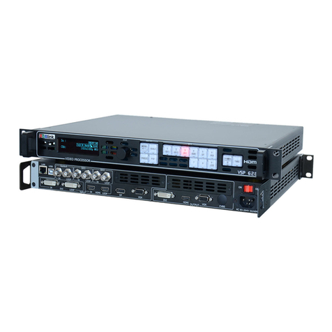
RGBlink VSP 628 User manual

–
Installation and cabling features
Rear Panel
Connections
15
8S-Video DIN 4
7
9
Gigabit copper port
Power
Step 1-Mounting
Turn off or disconnect all equipment power sources.
VSP 628 Quick Start
Rev 1.1
Page 1 of 7
Address: S603-604 Weiye Building Torch Hi-Tech Industrial Development Zone, Xiamen, Fujian Province, P.R.C
Tel: 00865925771197 Fax:00865925771202
IMPORTANT
Refer towww.rgblink.cnfor
thecompleteuser manualand
installationinstructionsbefore
connectingtheproducttothe
powersource.
1
25
26
27
23
Switch
Step 2-CVBS Input
This guide provides quick start instructions for an experienced installer
to set up and operate the VSP 628.
For full installation, configuration, and operation details, refer to the
VSP 628 user manual, which is available at www.rgblink.com.
DVI are used to connect the video
sources from HDD media player,
DVD player and computer.
NOTE
CVBS Output
~
14
VGA Input
21
22
24
Step 4-VGA Input
Connect NTSC, PAL or SECAM component
video to these female BNC connectors.
Input through computer or VGA
source (compatible with YPBPR).
Step 5-DVI Input
10/100M Interface
USB Interface
Small push button
RS232 Interface
2
3
4
5
DVI Input
10
1112
13 Power supply port of sending card
USB control port of sending card
DVI Input
16 SDI Input
SDI Loop Out
20CVBS Loop Out
~
18
17
S-Video Loop Out
VGA Loop Out
DVI Loop Out
28
DVI+VGA DVI Output
DVI Output
Step 3-S-Video Input
Used to input S-Video signal (PAL, NTSC,
SECAM compatible)
Step 6-SDI Input
Can receive signal from HD player and
HD camera.
Step 7-SDI Loop Out
Can connect the next level VSP 628 or the device
with SDI input.
Step 8-CVBS Loop Out
Can connect the next level VSP 628 or the device
with CVBS input.
Step 9-S-Video Loop Out
Can connect the next level VSP 628 or the device
with S-Video loop out.
Step 10-VGA Loop Out
Can connect the next level VSP 628 or the device
with VGA input.
Step 11-DVI Loop Out
Can connect the next level VSP 628 or the device
with DVI input.
CVBS Input

VSP 628 Quick Start
Rev 1.1
Page 2 of 7
Address: S603-604 Weiye Building Torch Hi-Tech Industrial Development Zone, Xiamen, Fujian Province, P.R.C
Tel: 00865925771197 Fax: 00865925771202
Step 18-Power
Plug in power cord which has IEC connector, VSP 628
support AC power from 85 to 265VAC, 50-60Hz, which
means world wide compatible.
Step 1-Set Output Resolution
1). Push 【MENU】to the main menu, use UP or
DOWN button to right OUTPUT, press OK to confirm.
2). Use UP or DOWN button to the right OUTPUT RES,
press OK to confirm.
3). Use UP or DOWN button to right DVI/VGA RES,
press OK to confirm, and use LEFT or RIGHT button to
open output resolution setting.
4). Spin knob to select the desired output resolution,
selected and press OK to confirm, press 【MENU 】to
return and exit Settings.
NOTE
Pin End 1 Wire Color End 2 Wire Color
1 White-green White-Orange
2Green Orange
3White-Orange White-green
4Blue Blue
5White-blue White-blue
6White-Orange Green
7White-Orange White-Orange
8Orange Orange
Crossover Cable CAT5 is
wired as
T568A at
one end
and T568B
at the other
is
crossover.
T568A T568B
Insert twisted
pair wires RJ-
45 connector
Pins
Step 17-Serial Port
Powering Up
Push power button switcher to ON position. LCD
module on the front panel will show RGBLINK and
VSP 628 model information, and go into self
verification before it load the last setting configuration
data and send the processed image to the target
displayer device. User can operate with VSP 628
through local front panel and remote control with the
software run on the PC, remote control by RS232, USB
or TCP/IP.
Use RS232 to RJ11 cable to connect a control system or
computer to the back panel RJ11 port and the other end
on RS232 port. RS232 to RJ11 cables as following
definition. RS-232 Function
2TX Transmit
3RX Receive
5GND Signal Ground
7--- Not used
8--- Not used
Pin RS-422 Function
TX- Transmit(-)
RX- Receive(-)
GND Signal Ground
RX+ Receive(+)
TX+ Transmit(+)
Insert twisted
pair wires
RS232/RS422
connector Insert
twisted pair
wires RJ11
Connector
RJ-11 Function
1
TX Transmit
2RX Receive
3GND Signal Ground4
--- Not used
Pin
Local Control-Front Panel Control
Step 16-USB Port
Connect control PC to USB port via USB cable.
Step 2-Input Switch
NOTE
Step 15-LAN (Ethernet) port
Use twist CAT5 cable to connect to LAN port, user can
control VSP 628 based on default IP address:
192.168.0.100. User can also change the IP address by
RS232 or USB. Twist CAT5 should be one end in
T568A, and another end in T568B standard. LAN
(Ethernet) port is not for standard configuration.
Step 13-Preview Output
Used to connect with DVI-based
monitor so as to monitor the status
of input signal, or connect VGA-
based monitor via a DVI to VGA
cable.
Step 12-Program Output
DVI to VGA adapter, it has
DVI-I male at one end and
VGA male at the other end.
Used to connect with DVI-based
display or LED control display.
DVI to DVI+VGA splitter cable:
one end is DVI-I or DVI-D male,
the other end is DVI-I or DVI-D
female together with VGA male.
Step 14-CVBS/SDI Output
Can receive signal from device with CVBS
or SDI input (the interface is VSP 628
optional module).
RGBLINK
VSP 628 RGBLINK
INPUT:CV1
NO INPUT
HDMI/VGA RESOLUTION
1024X768@60
INITIAL PROCESSOR
PLEASE WAIT A MINUTE
Plug 3 sec
3 sec
10 sec
VSP 628 supports 15 output resolutions as
follows:
800x600x60Hz,1024x768x60Hz,1024x768x75Hz,
1280x720x50Hz,1280x720x60Hz,1280x768x60Hz,
1280x1024x60Hz,1400x1050x60Hz,1440x900x60Hz,
1600x1200x60Hz,1680x1050x60Hz,1920x1080x50Hz,
1920x1080x60Hz,1920x1200x60Hz,2048x1152x60Hz.
VSP 628 can realize seamless switching between 2
channels , only need to switch to video wall channel to
choose, for example, key 【CV1 】light, then the
video wall output signal is channel 1, if you want to
switch to channel 2 signal, just press 【CV2 】and it
will achieve seamless switching.
Switching speed can be adjusted through
【DIMMER】button or (ALPHA) on PC software.

Remote Control-- Software Control
VSP 628 Quick Start
Rev 1.1
Page 3 of 7
Address: S603-604 Weiye Building Torch Hi-Tech Industrial Development Zone, Xiamen, Fujian Province, P.R.C
Tel: 00865925771197 Fax:00865925771202
NOTE
About how to install this
software in the WINDOWS operating
system, please refer to the user manual
and please select the correct language
version during installing process.
Choose useful RS 232 control port of computer, set
baudrate 115200.
Step 1-Set up communication
Step 4-Image Size and Position Setting
Communication
Communication button
Default IP: 192.168.0.100
Set the computer in a network segment with different IP
address, then communication, for example: 192.168.0.99
Step 3-SCALE and POSITION Setting
Step 4-PIP Setting
VSP 628 【PIP】button can realize dual picture and
single picture seamless switching. Most can output two
different channel signal to screen arbitrarily, also can
display two same channel same picture, specific
operation as follows:
1). Choose IMAGE1, for example, choose 【CV3】as
IMAGE1 signal, press 【CV3】button, it lights.
2). Press 【PIP】button to start PIP function, and LCD
screen prompt select PIP source.
3). SDI Choose Image2, press any key of 1-7, for
example, choose 【SDI】as IMAGE2 signal, press
【SDI】button, it lights. PIP source choice completed,
LCD screen display: INPUT CV3: SDI
For different channel, the output picture size and
position may be different, VSP 628 can realize different
channel image size and position arbitrarily regulating.
1). Press corresponding signal button to choose
corresponding signal, for example, choose 【DVI】.
2). Press 【SCALE】to enter scale menu, which has 2
parameters, respectively picture WIDTH and HEIGHT.
3). Combined with 【POSITION】key, which also has
2 parameters, level starting position POS X, vertical
starting position POS Y.
4). According to pictures display demand, choose
corresponding parameters and modify it to the needed
parameters via the knob, then press OK key to confirm.
Step 5-Save
NOTE If need to set PIP to 2 same channel signal,
just press the lighted IMAGE1 when choose IMAGE2.
If users need to set PIP size and position, specific
operations as follows:
1). Press 【MENU】, choose 【PIP SETTING】in
【OUTPUT】via knob, spin knob, choose IMAGE1 or
IMAGE2, press OK to confirm.
2). Press 【SCALE】or 【POSITION】, choose the
corresponding IMAGE2 items according to picture
display demand and LCD screen prompt. Set
corresponding image size and initial position via knob,
then press OK to confirm.
3). After setting, press 【MENU】to exit, and enter
【VIEW】to save.
NOTE
If need to switch to single picture, pres
【PIP】again, light out, and PIP is switched to single
picture.
Press 【MENU】, choose VIEW by UP/DOWN knob,
then choose SAVE, you can save current parameter to
SAVE1 or SAVE2, and it is default SAVE1 when re-
boot. User can also save to RECALL。
User can choose one window and PIP
by selecting from pull down list.
When the user choose one window,
click the mouse on Display mode to
choose input interface, if choose SDI input interface, the
white area display the name of input interface. The green
pane means current selected interface. as following:
If in PIP mode, user can
set the device to work in
PIP or PBP mode.
Step 3-Input Signal Setting
When user choose PIP mode, the default one window
chosen interface (green box) means selected interface
for channel 1. Click any port on the toolbar, such as
CV1, it can be channel 2 chosen input interface, The
red pane means selected interface for channel 2.
NOTE
Step 2-Output Resolution Setting
User can choose different output
resolution by selecting from pull
down list. VSP 628 has 15 output
resolutions for users selection.
User can scale by modifying the number or click drop-
down arrow, or dragging the edge of the image, and
easily change the size and position of the picture.
If user selects one window input mode, Images2 can not
be chosen.
Step 5-Save
VSP 628 Quick Start
Rev 1.1
Page 4 of 7
Address: S603-604 Weiye Building Torch Hi-Tech Industrial Development Zone, Xiamen, Fujian Province, P.R.C
Tel: 00865925771197 Fax: 00865925771202
NOTE
If user scale the image by modify the number on the
toolbar, they then need click to output image.
When user scale or position setting by dragging the
edge of the image, the edge of the chosen Image1 or
Image2 (as follows: selected Image2) appears red
box, and the square has divide eight red points.
1). User can customize image or images position and
size just by drag and drop image (images) in this area:
2). User can also long press left mouse button and
drag the image to preliminary setting position, as
follows:
Step 6-Recall
User can recall the saved Usermode1 or Usermode2,
it is default Usermode1.
User can save the current parameters to Usermode1 or
Usermode2.
User can also recall the saved Usermode1 or
Usermode2 through the icons below display bar.
NOTE
Step 7-Factory Reset
When there is wrong operation during parameter
adjustment, users can recall the device and readjust the
parameter by factory reset, click the follow icons to
initiate factory reset.

VSP 628 Quick Start
Rev 1.1
Page 5 of 7
Address: S603-604 Weiye Building Torch Hi-Tech Industrial Development Zone, Xiamen, Fujian Province, P.R.C
Tel: 00865925771197 Fax: 00865925771202
1SDI output interface BNC 2FIBER output interface SFP
1SDI output interface BNC
WEB SERVER Cross-platform Operation
NOTE
User can set the following 4 SDI
output resolutions according to their need:
1280x720x50Hz,1280x720x60Hz,
1920x1080x50Hz,1920x1080x60Hz.
Key operation menu as following:
Step 2-Output Resolution Setting
Enter the default home page, the system provides 15
kinds of output resolutions for choose, blue stripe
means current selected output resolution. Selected, then
VSP 628 will automatically update the output
resolution.
Users can freely switch the icons in title bar to set
relevant functions.
NOTE
Step 1-Set Up Communication
Click to run Google Chrome browser, open the
webpage and input 192.168.0.230
(default) to operate:
If users use ipad or iphone, they can input the website
192.168.0.230 (default) in Safari browsers to operate.
If users need to modify VSP 628 IP address, they can
input corresponding modified IP address.
If users use other device, they need to install webkit
kernel browser, such as: apple Safari, Google Chrome
or Maxthon. Installation package provides Google
Chrome browser (Windows version). Now take
Google Chrome browser for example, specific steps
are as follows:

Step 3-Input Signal Switching
Select "Input" icon in title bar, user can click the signal
source that need, select, VSP 628 will automatically
update input signal source.
VSP 628 Quick Start
Rev 1.1
Page 6 of 7
Address: S603-604 Weiye Building Torch Hi-Tech Industrial Development Zone, Xiamen, Fujian Province, P.R.C
Tel: 00865925771197 Fax: 00865925771202
Step 4-Image Size and Position Setting
Select "Image" icon in title bar to scale the image, user
can modify digital setting parameters and image size
and position easily through "-+" icon. Click "Set" after
modify the digital, VSP 628 image will display the
latest Settings;
Step 5-PIP Setting
Select "PIP" icon in title bar. When the PIP sliding
block icon is grey, then it is single channel picture
mode, and if image selection is gray, then image 1 is
default for single image output image, and can't be
chosen.
Then user can set PIP location, in addition to system
default PIP upper left picture, also can choose picture
above picture and picture edge picture.
In PIP mode, the default image1 is the main image,
image2 for PIP image2, click the corresponding image
when need to edit image1 or image2 , the selected
image with blue stripes, tick, as shown below: image2
is selected, all all settings will for image 2. For
example, you can switch "Input" icon in title bar to
choose image 2 input source.
NOTE
If image1 and image2 with the same input source, then
it will display the same picture in PIP.
Step 6-Save and Call
User can save the parameters to UserMode1 and
UserMode2, and can also load UserMode1 and
UserMode2 that saved before.

VSP 628 Quick Start
Rev 1.1
Page 7 of 7
Address: S603-604 Weiye Building Torch Hi-Tech Industrial Development Zone, Xiamen, Fujian Province, P.R.C
Tel: 00865925771197 Fax: 00865925771202
Step 7-Other Setting
First, choose the language according to user’s need.
And the default is automatic identification.
"Set" after select the language (such as select Chinese),
pay attention to system prompt "Language will effect
after the next time and after reboot IP will affect" (at
green box); Now you need to refresh the page to
complete the setting.
Reset: If appear wrong operation, click "Reset" to
factory default.
Key Lock: If slide block is gray, it is unlock, and VSP
628 keys can normally operate; And if slide block is
green, the VSP 628 keys lock, and user can't operate
any button.
Dimmer: ALPHA transparency regulation. Drag ball
to change the transparency value, transparency value
is between 0 ~ 100 levels.
If need to modify IP address, also click "Set" after input
the IP address, pay attention to system prompt
"Language will effect after the next time and after
reboot IP will affect" (at green box); Now you need to
click “Reb...” to complete the IP modify.
Operation is invalid in PIP mode.
NOTE
Table of contents
Other RGBlink Media Converter manuals

RGBlink
RGBlink D8 User manual

RGBlink
RGBlink TAO 1Mini-N User manual

RGBlink
RGBlink MSP Series User manual

RGBlink
RGBlink FLEX RS1 User manual

RGBlink
RGBlink D8 User manual

RGBlink
RGBlink GX2L User manual

RGBlink
RGBlink Q4L User manual

RGBlink
RGBlink VSP 3500 User manual

RGBlink
RGBlink X14 User manual

RGBlink
RGBlink D8 User manual

RGBlink
RGBlink venus x2 User manual

RGBlink
RGBlink MSP 210H User manual

RGBlink
RGBlink VENUS X8K LEGENDARY User manual

RGBlink
RGBlink VSP 737 User manual

RGBlink
RGBlink VSP 198CVS User manual

RGBlink
RGBlink VSP 310 User manual

RGBlink
RGBlink VSP 516 Series User manual

RGBlink
RGBlink FLEX RS1 User manual

RGBlink
RGBlink MSP 325N User manual

RGBlink
RGBlink VENUS X1PRO User manual