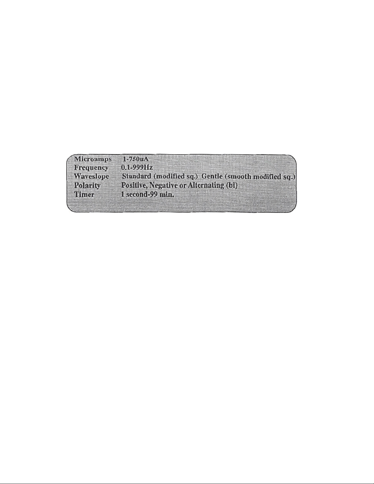
Axion micro5 User manual

1
AXION micro5 Instruction Manual
Read This First
THIS INSTRUCTION MANUAL IS THE MOST IMPORTANT ACCESSORY OF THE MICRO5.
IT SHOULD BE READ AT LEAST TWICE BEFORE OPERATION OF THE INSTRUMENT.
THE MICRO5 IS A VERY ADVANCED ELECTRONIC DEVICE. THE MICRO-PROCESSOR
CONTROLS ARE DESIGNED TO SIMPLIFY TREATMENT DELIVERY. WE HAVE MADE
THE OPERATION OF THE micro5 VERY SIMPLE IF YOU FOLLOW THE BASIC GUIDE-
LINES OF THE INSTRUCTION MANUAL. REMEMBER, MOST PROBLEMS ARE A RESULT
OF FAILURE TO FOLLOW DIRECTIONS RATHER THAT EQUIPMENT FAILURE.
THE MICRO5 IS SHIPPED WITH A LOW BATTERY CHARGE. IT MUST BE CHARGED AT
LEAST 15 HOURS BEFORE FIRST USE.
IF YOU HAVE DETERMINED THAT A SYSTEMS FAILURE EXISTS, CALL FOR INSTRUC-
TIONS.

2
Power Up
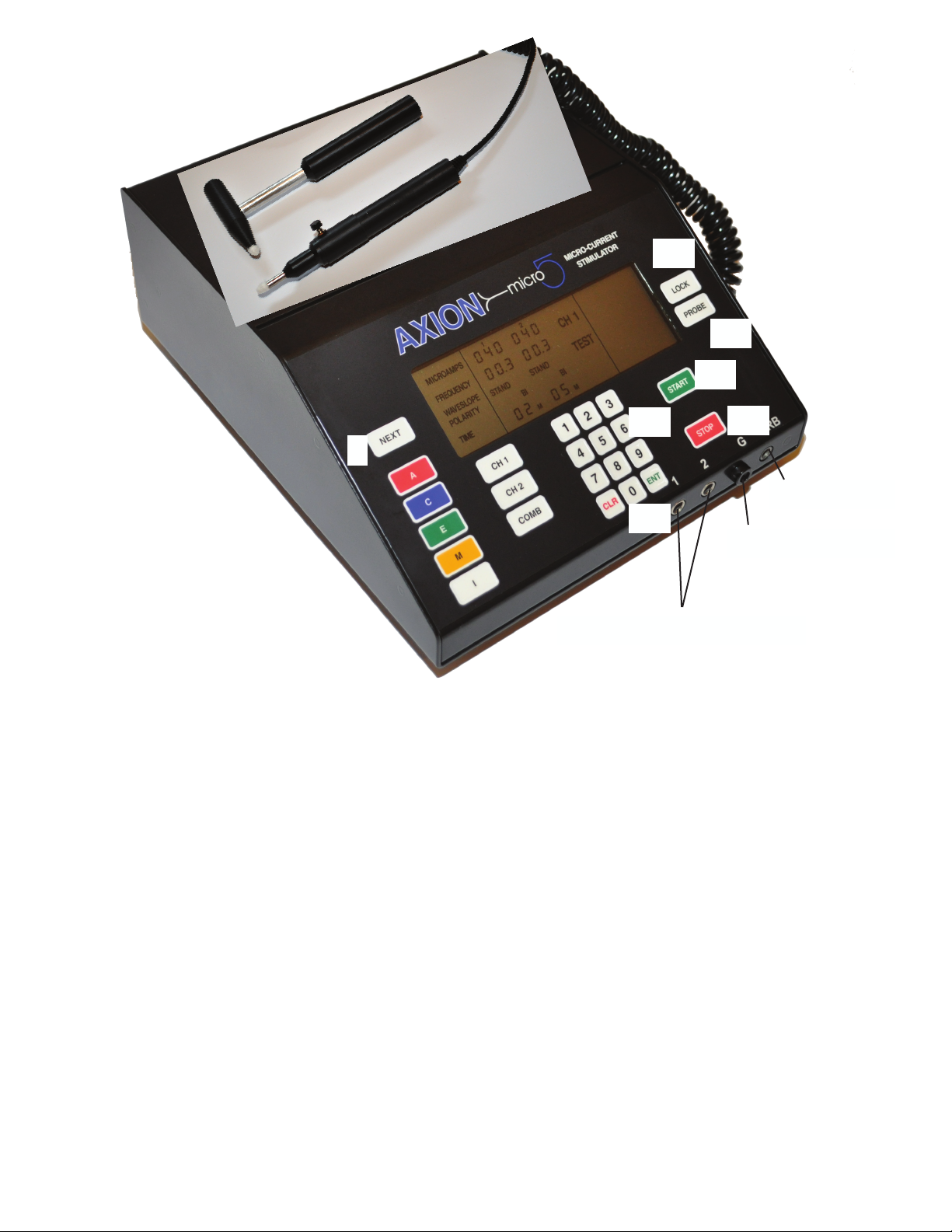
The micro5 is turned ON by a momentary switch located on the back of the instrument, in the lower Right
hand corner. The switch will activate the unit with a slight touch and the entire LCD display will light up.
The micros has a built in battery saver that will automatically turn the unit off within ve minutes of idle
time. When the micros is turned on again it will display the last treatment settings used. NOTE: The ON
switch does NOT turn the unit off. The unit powers down automatically after ve minutes of idle time.
When the instrument is rst turned on, it will run an internal self-diagnostic test lasting about three sec-
onds. During this test all the LCD segments will display. A successful test will be followed by a series
of alternating high and low tones indicating the instrument is ready for operation. A failure of the test is
followed by a series of tones along with a ashing TEST indicator on the LCD screen. If the micros should
fail a power-up test, contact us for instructions. To facilitate return shipping in the event of a failure, we
recommend keeping the original shipping container.
Introduction
Microcurrent instruments use very small amounts of current (micro-amperage) to treat many of the same
conditions normally associated with high output (milliamperes) instruments. Microcurrent stimulation is
usually sub-sensory and often imperceptible to the patient. The current is able to pass through the skin with-
out much stimulation to motor or sensory nerves. Therefore, microcurrent stimulation is comfortable to the
patient and enhances patient compliance.
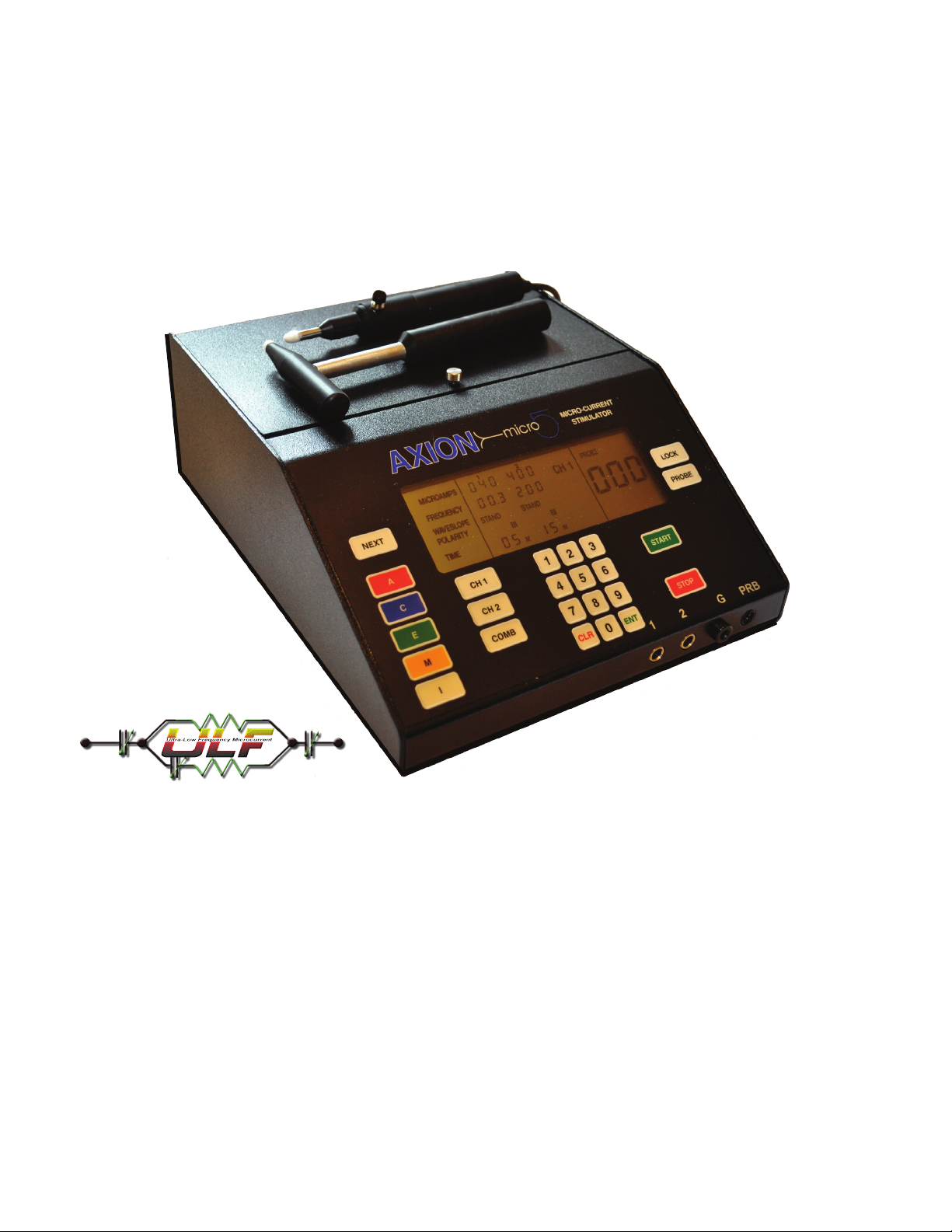
The AXION micro5 low volt, pulsed micro-amp stimulator utilizes micro-processor controls and touch pad
operation. The ease of operation allows the clinician to quickly, accurately and efciently administer the
desired treatments to the patient. In addition, by using pre-programmed presets, the micro5 reduces confu-
sion of treatment selections often associated with microcurrent stimulators. A full manual over-ride is also
offered for the clinician who wants to customize a treatment for a patient.
For the clinician, novice or experienced in microcurrent stimulation, the micro5 provides an easy to operate,
yet highly sophisticated therapy system. The outstanding clinical results you will achieve with microcurrent
stimulation will convince you of its place in a comprehensive pain management program.
The AXION micro5 is the most advanced microcurrent stimulator available. Each time the micro5 is
turned on it performs the following self-diagnostic tests.
RAM, ROM, CPU, Display, Output tests
During operation the micro5 uses distinct and different tones as well as display indicators to alert the opera-
tor of systems problems.

3
12345
Front Panel Operation
1. “A”. Pressing this red key sets the parameters of the selected channels for the “A” default.
2. “C”. Pressing this blue key sets the parameters of the channels selected for the “C” default.
3. “E”. Pressing this green key sets the parameters of the selected channels for the “E” default.
4. “M”. Pressing this yellow key sets the parameters of the selected channels for the “M” default.
5. “I”. Pressing this white key sets the parameters for the channels selected for the “I” default.
6. CH 1. Press this key to program channel one.
7. CH 2. Press this key to program channel two.
8. COMB. Press this key to program both channels at once.
6
78

4
9
9. NEXT. Pressing this key when programming the waveslope or polarity will toggle between the
various options available. This key also allows access to m5 special features
10. PROBE. Pressing this key turns on the probe operation and the three segment LCD probe
display.
11. LOCK. This key locks the Search display readings on the screen.
12. START. Pressing this key starts the countdown operation of the instrument. It
will also silence the beep that is heard every ten seconds during operation.
13. STOP. Pressing this key suspends treatment.
14. KEY PAD NUMBERS 0-9. These keys allow manual programming of the various parameters and
access to special features.
15. CLR/ENT. Pressing these keys will either clear and entry made or enter the selection and ad
vance to the next parameter to program.
10
11
12
13
14
15
Pad lead wires
Active Probe
Indifferent Probe

5
micro5 Features
Pre-programmed Treatment Modes
The AXION micro5 is the rst microcurrent instrument to offer six pre-programmed treatment modes. This
feature allows the clinician to set the output, frequency, waveslope, polarity and treatment times at the touch
of a single keypad. These treatment modes represent the most effective applications available for microcur-
rent stimulation.
The following table illustrates the parameter setting for each of the modes. These values will appear on the
LCD screen when the mode is selected.
A C E M I Probe
uA 400 200 40 100 400 200
Hz .6 .3 .6 200 100
Wave gentle standard standard standard standard standard
Polarity bi bi bi bi bi bi
Time 15 min 15 min 15 min 15 min 15 min 10 sec
Just press the preset button and then Start.
Full manual over-ride is also available for fully customized treatments.

6
Using Presets
The preset treatment regimens of the micro5 have been determined after years of clinical use. They represent
the most effective parameters for those indications. However you can manually over-ride and vary any of the
parameters especially if you have preferred settings or are not getting the desired results.
With microcurrent stimulation it is important to determine the type of pain being treated. Upon evaluation, try
to identify the pain as acute or chronic.
Electrical stimulation is still part science part art. There have not been denitive settings established for vari-
ous conditions. However some general guidelines can be used with condence.
1.”A”.The “A” preset can be used for acute pain patients. The settings are designed to bring about the most
rapid pain relief. If you feel the condition is an acute exacerbation of an existing condition then treat with “A”
for 15 minutes followed by “C” for 15 minutes. If inammation is present use “A” for 15 minutes followed by
“E” for 15 minutes.
2. “C”. The “C” preset can be used with low grade pain patients. Dull, aching pain would be a typical descrip-
tion of the pain usually treated with “C”.
3. “E”.The “E” preset can be used if there is inammation present. This setting can be used after treatment us-
ing another preset.
4. “M”.The “M” preset is user dened. See section on new features.
S.”I”.The “I’ preset is used when a large area is treated. This preset uses both channels to deliver the current
through four pads. The micro5 uses both a rate scan and vector scan. When using the “I” preset you will notice
the numbers on the display might change rapidly during treatment. This is normal and reects the operation of
the rate and vector scan. To over-ride the “I” preset settings, press “ENT ‘ then enter the parameters you want,
then press START.
After the instrument has been turned on and successfully passed the diagnostic check, it can be programmed
for treatment. Select the channel to be used or press COMB to program both channels at once. (A tone should
be heard whenever a panel key is pressed. This conrms a selec tion has been made. If you do not hear a tone,
press the button again until a tone is heard.) When a channel has been selected, the MICROAMPS setting
will ash for that channel. This conrms that programming can begin. Now simply select the desired preset
(A,C,E,M or I).
The settings for that selection will now appear on the LCD display for that channel. If these are the settings
you want you may begin treatment by pressing START. After the START key has been pressed you will see
the minute or second indicator in the time eld begin to ash. This con rms that treatment has begun and the
timer is counting down. Every ten seconds during treatment a beep is heard to conrm that the instrument is
running. This beep can be turned off by pressing the START key during treatment. After time has elapsed, a
series of tones are heard to signal the end of treatment.

7
To Recap:
1. Select Channel
2. Select Preset
3. Press START
Adjustable Parameters
The micro5 provides you with complete control over the following parameters; microamps, frequency,
waveslope, polarity and time. This allows for maximal exibility when programming treatment param-
eters for each patient
The Parameter Ranges Are As Follows:
Manual Override
To enter settings other than the presets proceed as follows:
Micro-amps
Select the channel(s) to be programmed. When the micro-amp eld is ashing you may enter any range from
1-750uA using the numerical key pad. If the micro-amp eld is the only eld you want to change you do not
need to press the ENTER key, you may proceed to the START key. For example if you wanted to enter 600 uA
you would press 6,0,0.To enter 60uA you do not need to press 0,6,0. Simply press 6,0. If you make an entry
error or change your mind you can press the CLR key to clear the entry and start again. Pressing CLR clears
only the parameter being programmed and not the remaining parameters. NOTE: any entry above 750uA will
default back to 750uA. After the settings are entered you can move to the next parameter by pressing the ENT
key. To pass over a parameter simply keep pressing the ENT key until you have reached the parameter you
want to program.
Frequency
When entering the frequency settings use the 0 key to enter frequencies less than one. For example to enter
.6Hz you would press 0,6. To enter numbers greater than .9 simply enter the number direct. l5OHz would be
enter as 1,5,0. If you want to change the waveslope press ENT after the frequency has been entered.

8
Waveslope
To change the waveslope the waveslope indicator must be ashing. Pressing the NEXT key will toggle you
between the two selections available, Standard or Gentle.
Polarity
To change the polarity the polarity indicator must be ashing. Pressing the NEXT key will toggle you between
the three setting available, Positive Only, Negative only, BI (Alternating)
Time
To change time the current time must be ashing. Seconds are entered by beginning the entry with 0. For exam-
ple ten seconds would be entered as 0,1,0. A correct seconds entry will be followed by the time indicator chang-
ing from minutes (m) to seconds (s). Minutes are entered by pressing the desired time directly. For example ten
minutes is entered by pressing 1,0. To change from seconds to minutes press the CLR key
After all parameters have been entered and you want to make a change, simply press the ENT key until the
parameter you want to change is ashing. Now make the change. You do not have to press CLR to make your
change.
You may program both channels at once by pressing the COMB (combined) key.
You may press the START key at any time during programming. You do not have to be in the time setting to
start. After pressing START, the parameter eld will stop ashing and the time indicator (m or s) will begin to
ash. This conrms the timer is counting down. Every ten seconds you will hear a beep to conrm that the unit
is still counting down. To turn off this tone simply press the START key again. This operation will toggle you
between tone on and tone off.
You can interrupt a treatment by pressing the STOP key. Because the micro5 uses independent timers for each
channel you must be in the channel you want to stop to actually stop that channel. For example to stop only
channel one while both channels are running, press CHI then STOP. If you want to stop both channels you may
press COMB then STOP. Pressing the START key after STOP will resume the treatment where you left off.
After the timer has timed out, the micro5 will hold the current settings in memory until any changes are made.
The instrument will go into a “sleep” mode ve minutes after time has expired.

9
Delivering Current
The micro5 delivers the current either from standard electrodes, or in the Probe Mode using Q-Tips moist-
ened with tap water. We supply a sample of reusable self-adhesive electrodes. These types of electrodes
are readily available for sale through several places on the Internet, or through us.
When using Q-Tips, please purchase the paper shaft Q-Tip brand. There really is a difference. Never use
the plastic shaft (they don’t conduct electricity), and be sure to watch the instruction video on the proper
insertion of the Q-Tip.
Reusable electrodes have a life span of about 4-5 uses. The micro5 will alert you through it Secure Alert
warning tones if the electrode is failing.
If using reusable electrodes, make sure you prep the skin using alcohol swabs to remove as much skin oils
as possible. Oil does not conduct electricity AND it quickly breaks down the adhesive gel of the electrode
which is designed to both adhere to the skin and conduct electricity.

10
The AXION micro5 comes with two probes. (Active and Indifferent).
The probe with the button is the active probe used during treatment
and conductivity measurements. The probe is handy to treat irregular
body areas.
The black switch on the probe is a momentary one. You need only to
touch it once. Pressing this button is the same as pressing the START
key. In fact, should the button ever fail to begin the timer countdown
you may press the START key to over-ride the probe start button.
CAUTION: REMOVE THE PROBE AFTER USE. LEAVING THE PROBE PLUGGED IN WILL
CAUSE A FAILURE TEST TO APPEAR IN CHANNEL ONE IF YOU ARE TRYING TO USE THE
PADS IN CHANNEL ONE.
Using the Probe
1. Press the PROBE key
2. Have the patient hold the metal part of the Indifferent probe in the hand to be treated.
3. Place a well moistened cotton swab tip into the end of the probe shaft The swab tip should be broken
off just below where the cotton attaches to the shaft. Use only paper shafted swabs. The cotton tip
delivers the current. Make sure it is both wet and making good contact with the metal sides of the
probe. See Video
4. Scan the area to be treated. You will notice that when contact with the skin is made the micro5 emits a
tone. This tone rises and falls in pitch as the resistance increases and decreases. The higher the pitch
the lower the resistance. You will notice the numbers on the LCD display will rise and fall. You are
looking for the highest pitch in the area to be treated.
5. Press the black button on the probe to begin treatment. The seconds or minute indicator in channel one
will begin to ash to signal timer countdown.
6. To leave the probe mode press the PROBE key.
When using the probes, both active and indifferent must be in contact with the body at the same time. Either
both wet Q-Tips are used, or the active probe is used while the patient holds the metal part of the indifferent
probe in their hand, usually on the same side of the body as is being treated.
Remember to remove the probe from the unit to use pads in channel 1.
Use one cup of tap water with 1/2 teaspoon of table salt added. This creates a normal sa-
line solution. Moisten the Q-Tips before inserting into the probes, and then for 10 seconds
after inserting. Re-moisten after treating 2-3 points, or each muscle.
Using the Probe
Indifferent
Probe
Active Probe

11
Metal to Metal Tap Water Saline Solution
Using wet Q-Tips is the most eective and sanitary method of delivering the microcurrent to the patient/client.
You MUST use a solution that is capable of moving the electrons through the solution. Not all are created equal.
Below are three pictures of conductivity using the probe meter of the micro5 as a simple conductivity meter. e
higher the reading on the meter the better the conductivity.
e best conductivity is metal to metal, shown on the far le. e middle picture shows a q-tip moistened with
tap water. e far right picture shows the tap water q-tip re-moistened with a saline solution made up of our
special salts compound.
It’s clear that when using moistened q-tips they should be soaked in a saline solution. Doing that eliminates one
variable you can control.
1/2 Teaspoon of our mi-
cro5 Electrolyte salt to
8 oz of water
Equals a normal saline
solution.
Our special salts compound contains Sea Salts, Himalayan salt and Sel Gris. In the proper proportions, this
combination of salts creates an amazing electrolytic solution of minerals important to muscle and nerve
function, and to overall health.
It is recommended that you create a master blend of the solution in a larger container and then portion it out
for each patient/client using disposable Dixie cup type of containers. Aer each session you will dispose of
the used saline solution and q-tips. is prevents cross-contamination between patients/clients.
Contact us about ordering our special salts compound.

12
A unique feature of the AXION micro5 is PROBE LOCK. Pressing this key while in the probe mode allows
the clinician to scan the area for exactly two seconds. After two seconds the highest reading encountered will
remain on the LCD display until another point is touched.
Using PROBE LOCK
1. Press the PROBE key.
2. Press the LOCK key. The word LOCK should appear in the upper portion of the screen. 3. To disable
probe lock press the LOCK key again.
This feature is also very useful in measuring the electrode/skin interface to determine if
good contact is being made before electrode use.
Probe Lock
During operation the micro5 uses distinct and different tones as well as display indicators to alert the opera-
tor of systems problems. The indicator are as follows.
Upon Start Up
An alternating series of high and low tones indicates a successful initial start up test.
During Operation
A series of descending tones along with a ashing battery indicator and ashing test
indicator means a low battery charge. You should charge the battery as soon as possible.
A series of descending tones along with a ashing test indicator and ashing channel indicator indicates a
current test failure.
The AXION micro5 utilizes a unique monitoring system called INSTANT ALERT. During treatment IN-
STANT ALERT works in the background to measure the amount of electricity delivered to the patient Be-
cause the micro5 is a computer driven constant current generator it will always strive to maintain the settings
you have entered regardless of skin impedance. There are several things that will cause INSTANT ALERT to
issue a current test failure.
Note: INSTANT ALERT will indicate which channel is failing by ashing TEST along with the appropriate
channel indicator.
MAKE SURE THE MAIN PROBE IS UNPLUGGED BEFORE USING ELECTRODES IN CHANNEL

13
ONE.
1. Low Battery. If batteries are too low, proper output cannot be maintained. If the battery charge indicator
is ashing, charge the batteries as soon as possible. See section on batteries to determine voltage.
2. Defective lead wires. If there is a break in the lead wires INSTANT ALERT will show a current test fail
ure. To test for lead wire failure plug a set of lead wires into channel 1. Press the PROBE button to enter
into the probe mode. Touch the exposed lead wire metal tips together. The LCD probe display should
read over 400. If it does not this means a break somewhere in the lead wire. Shake the lead wire to see
if the break causes an intermittent problem. Replace the defective lead wire.
3. Defective electrodes. Carbon Silicone electrodes have a natural useful life of about 6-8 months. Bad
electrodes can impede the ow of current and cause INSTANT ALERT to issue a current test failure. Try
a new set of electrodes.
Multi-application electrodes have several components that can break down and cause a failure. Even new elec-
trodes can be bad. Try another pair.
CAUTION: THERE ARE NO USER SERVICEABLE PARTS OTHER THAN BATTERIES. DO NOT OPEN
THE INSTRUMENT WITHOUT INSTRUCTIONS FROM THE COMPANY.
The probe is also connected to the INSTANT ALERT system. Breaking contact with the skin during treatment
will cause a current test failure.
Note: INSTANT ALERT current test operates by capturing samples to measure against what is entered on the
screen. At lower frequencies it may take the microprocessor a little extra time to nd a sample to measure. This
will account for the slight lag in showing a failure in the lower frequencies.
The AXION micro5 uses a combination of power sources.
Display Memory
One button type lithium battery not accessible to the user. When this battery fails the instrument will no longer
display the last entry upon start up. The unit must be returned to us to replace this battery.
Main Processor Board and Output
Three high capacity “D” size NiMH batteries. Recharge these batteries using the supplied USB charger, Com-
puter USB port or auto USB port. Charging time is about 6 hours for a full charge. When charging make sure
the charging indicator light is on. This light is located on the back of the micro5. The low battery indicator will
turn on when it is time to recharge. THE UNIT CANNOT BE USED DURING CHARGING.
To keep the channels isolated, channel two has its own rechargeable power source. These batteries are recharged
at the same time the main batteries are recharged so no extra steps are needed.
During charging the micro5 will turn it self off. This prevents operation with the charger plugged in. TURN
THE MICRO5 OFF BEFORE CHARGING. Should the device ever fail to turn on, make sure that the charging
cord is not plugged into the back of the device. If unit still fails to turn on, contact Company.

14
CPT Billing Codes Suggestions
64550 (TENS)
97118 (electrical Stimulation)
97200 (physical medicine, combined modalities, 1/2 hr.) 97201 (additional 15 min. added to 97200)
97014 (electrical stimulation)
Contraindications
1. Do not stimulate over the Carotid Sinus region.
2. The use of T.E.N.S. on individuals with demand type cardiac pacemakers may be hazardous.
3. Do not stimulate transcerebrally (through the head).
4. Do not use T.E.N.S. whenever pain syndromes are undiagnosed until the etiology is established.
Warnings
1. The safety of T.E.N.S. devices for use during pregnancy or delivery has not been established.
2. T.E.N.S. is not effective for pain of central origin.
3. T.E.N.S. devices should be used only under the continued supervision of a licensed practitioner.
4. T.E.N.S. devices have no curative value.
5. T.E.N.S. is a symptomatic treatment and as such suppresses the sensation of pain which would other
wise serve as a protective mechanism.
6. The user must keep the device out of the reach of children.
7. Electronic monitoring equipment such as ECG monitors and ECG alarms may not operate properly
when T.E.N.S. stimulation is in use.
Precautions
1. Isolated cases of skin irritation may occur at the site of electrode placement following long term
application.
2. Isolated cases of electrode burns to the skin may occur.
3. Effectiveness is dependent upon patient selection.
Caution: Federal law (USA) restricts this device to sale on or by the order of a licensed practitioner.

15
Special Features
Battery Voltage Check (NEXT 0)
The relative voltage of the main processor batteries may be checked during operation of the micro5. This
will give you an idea of how much power is left in the batteries. To check the batteries do the following.
While the instrument is operating, press the NEXT key followed by 0 on the numerical key pad. In the probe
display area you will see a three number display. This is the voltage of the processor batteries. This display
will only stay on for about 1.5 seconds. For instance a reading of 300 is actually 3.0 volts. It is important to
check the voltage only during treatment. This will put a load on the batteries and give a truer reading. At rest
readings may be falsely high. Readings of 3.5v and above indicate a good reserve. At 3.0 and below the bat-
teries should be recharged as soon as possible.
Continuous Operation (NEXT 1)
Pressing the NEXT key followed by 1 on the numerical key pad allows continuous operation of the micro5
regardless of the time indicated on the timer. The instrument will continue to operate but the timer will not
count down. The instrument will remain in the continuous mode until NEXT, 1 is pressed again or until the
instrument is turned off by the On/Off switch on the back of the unit.
Display Current (NEXT 2)
This feature is used to display the relative output of channel one, measured in micro amps. This feature is
used by the factory for diagnostic purposes.
Disable Tone During Current Failure ( NEXT 3)
Should Factory determine that the failure of a m5 to pass the current test is a false failure, the current test
warning tones can be turned off until the device can be returned to us for repair. This will allow the use of
the device without the tones being heard.
NEXT 4,5,6 ARE FOR factory USE ONLY. SHOULD YOU PRESS NEXT AND THEN EITHER 4,5 OR
6, TURN OFF THE DEVICE AND TURN BACK ON. THIS WILL RESET THE DEVICE TO ORIGINAL
SETTINGS.
Increase/Decrease Probe Sensitivity (NEXT 7, NEXT 8)
By pressing NEXT 7 and then a 2 digit number, you will increase the probe sensitivity by the percent of the
2 digit number you entered. For example: Pressing NEXT 7 and then 5-0,will increase the sensitivity by
50%. You must be in the probe mode for this to have an effect. To reset, leave the probe mode and then re-
enter the probe mode. To decrease the probe sensitivity, press NEXT 8 and then enter a 2 digit number. This
time the sensitivity will decrease by the percentage of the 2 digit number.

16
Memory
The micro5 offers an open memory option for the clinician to program a specic treatment. The output, fre-
quency, waveslope, polarity and time can be programmed and stored for later recall.
To store a MEMORY preset (Button “M”).
1. Set all desired parameters in CHl.
2. Press CHl followed by NEXT and then press the “M” preset.
3. The settings are now stored and can be recalled for later use in either channel one or two.
Sequential Treatment (chaining)
The micro5 allows the clinician to link two treatments together to form a single continuous treatment. This is
sometimes called “chaining”.
To sequence treatments:
1. Press the keypad for the desired preset.
2. Press NEXT, then press the key for the second preset.
3. Press START
During programming the display will only show the rst preset. The display will show the second preset after
the rst has timed out. Once steps one and two have been performed, you can alter the settings of the rst
preset before pressing start.
Sequencing can be run on both channels simultaneously and independently.

17
More about the “I” Interferential Preset
Your AXION micro5 has a very special factory preset for microcurrent interferential. This setting is very
useful in bathing a larger area with the stimulation. Below is a very simple explanation of how interferntial
works
The basic denition of interferential therapy is the use of two channels of stimulation crossing each other
at 90°angles. At the point of intersection, an interference pattern is created (beat frequency) that is the dif-
ference of the frequencies of the two channels. For example: If channel one is 900 Hz and channel two is
950Hz, the beat frequency created by the intersection of the two currents would be SO Hz (950-900). This
third “beat” frequency is produced inside the body and radiates outward at 45° angles as shown in g.1.
This gure shows a line representation of “Static Interferential”.This representation holds true if both
channels have the same microamp output.
However if the output of the channels is varied, the current path of the beat frequency can be moved. This
technique called “Vector Scan” is used to move the beat frequency path over a greater area. This is illus-
trated in g.2.
Using the “I” Preset ch 1.
When you press the “I” preset you will notice that both chan-
nels are ready for programming.
BOTH CHANNELS MUST BE USED. The microamp default for both chan-
nel is 400.
Static Full Field with vector scan
The output of channel 1 is 900 Hz. This is xed and cannot be changed. The
default frequency of channel 2 is 150 Hz. This actually represents 1050 Hz.
When the start key is pressed the frequency of channel two will begin to scan
from 0-150. This is called “Rate Scan”.This represents 900-1050 Hz It is
displayed as 0-150 to show you the beat frequency being created. If you want the beat frequency to be a
certain number it can be changed, however if it is changed it will no longer scan.
You will also notice that during interferential operation, the microamp outputs of channels 1& 2 increase
and decrease. This is Vector Scan and is used to create a full-eld effect to bathe a larger area with the
stimulation. The channels will vary about +/- 30% of the set value. For example, if 500 is the set value to
Vector Scan, the value of channel two will scan down to about 350 while the value of channel 2 will scan
up to about 650.
NOTE: Each time you want the Rate Scan Vector Scan option, you must press the “I’ preset. After stop-
ping, the channels will reset to a static mode. If you want to reset to the Rate Scan/Vector Scan, press “I”.
Also note that after auto-shutoff in the “I” preset that the frequency of channel 2 resets to 000.

18
Charging System
The smart charging system on the micro5 uses a USB charging system. The unit comes with a dual-pur-
pose wall module and a standard USB A to B cable. For the fastest recharges use the 2.1A socket on the
charger module. YOU can use the 1A socket but the recharge time will take twice as long.
The micro5 can also recharge from your computer’s USB outlets or a car USB socket. Recharge time from
dead is about 12 hours. The nickle metal hydride batteries we use do not have a “memory” so it’s OK to
recharge at any time.
NOTE: It is wise to NOT leave the charging module in the wall when not in use. Leaving it in the wall will
shorten the life of the charging module. The micro5 cannot be used while it is charging.
IMPORTANT NOTE:
It takes the micro5 12 hours to fully charge. To fully charge the micro5, plug the wall module into an AC
outlet and then plug into the micro5 using the USB cable. After four hours of charging, unplug the USB
cable from the back of the micro5 momentarily and then plug back in. This resets the charging system.
Charge for another four hours.
The unit will not fully charge if left in for the full eight hours without momentarily unplugging and plug-
ing the unit.
A B
Green light on the back of the
micro5 unit turns on during
charging. It shows that cur-
rent is reaching the batteries.

19
Quick Charging System
Anker Astro3E 10000mAh external battery pack
Several companies manufacture external battery packs
that can be used to quickly recharge the AXION micro5.
We have tested and recommend the Anker Astro3E.
Our tests show that the Anker can recharge the micro5
from dead batteries to 90% charge in 1 hour.
NOTE: It does not power the micro5. It recharges the
micro5’s batteries on the go or in an emergency.
You can nd this device on the Internet and at Amazon.
com.
AXION micro5 being charged by the Anker Astro3E

20
Battery Access
Under normal circumstances you should not need to access the battery packs used by the micro5. Only ac-
cess the batteries after communicating with VenturaDesigns for complete instructions.
The micro5 uses two battery packs. The rst uses 3 “D” cell rechargable batteries. This powers the main
board and Channel 1. The second powers Channel 2.
The D cell battery pack is located inside the unit and is acessible by removing the four screws around the
handle on the back of the unit and carefully sliding the tray partly out.
Next remove the four screws that hold the metal plate over the batteries. You now have access to the D cell
batteries.
The second battery pack that powers Channel 2 contains 3 “AAA” batteries. It is located inside the storage
compartment. Slide the top off the battery case and you have access to the AAA batteries.
Table of contents
Other Axion Medical Equipment manuals