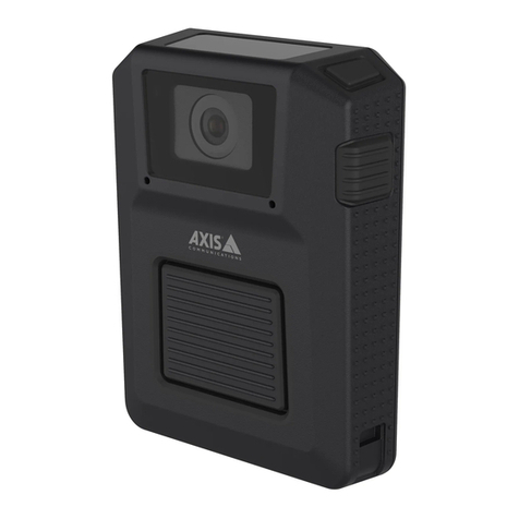
Axis T90C10 User manual

ENGLISH DEUTSCH ITALIANO ESPAÑOL
USER GUIDE
FRAN
Ç
AIS
AXIS T90C10 Fixed Dome IR-LED
AXIS T90C20 Fixed Dome IR-LED


ENGLISH
ENGLISH
Safeguards
Please read through this User Guide carefully before installing the product. Keep the User Guide for further
reference.
CAUTION!
• When transporting the Axis product, use the original packaging or equivalent to prevent damage to the
product.
• Store the Axis product in a dry and ventilated environment.
• Only use handtools when installing the Axis product, the use of electrical tools or excessive force could
cause damage to the product.
• Do not use chemicals, caustic agents, or aerosol cleaners. Use a damp cloth for cleaning.
• Only use accessories and spare parts provided or recommended by Axis.
• Do not attempt to repair the product by yourself, contact Axis or your Axis reseller for service matters.
IMPORTANT!
• This Axis product must be used in compliance with local laws and regulations.


AXIS T90C10/T90C20 Fixed Dome IR-LED User Guide Page 5
ENGLISH
AXIS T90C10/T90C20 Fixed Dome IR-LED
This guide provides instructions for installing the AXIS T90C10/ AXIS T90C20 IR-LED with the
following fixed dome cameras:
• AXIS P3343-VE
• AXIS P3344-VE
• AXIS P3346-VE.
To install the camera, refer to the installation guide supplied with the product.
The contents of this guide are as follows:
1.
Package Contents
. See below.
2.
Installation
, on page 8.
3.
Specifications
, on page 12.
Package Contents
Item Models/variants/notes
Lighting Module • PoE Cat 5 cable
(for AXIS T90C20 Fixed Dome IR-LED)
• 18-56V DC Power Control cable
(for AXIS T90C10 IR-LED)
Printed materials AXIS T90C10/T90C20 Fixed Dome IR-LED User Guide
(this document), Axis Warranty Document

Page 6 AXIS T90C10/T90C20 Fixed Dome IR-LED User Guide
Hardware Overview
AXIS P33 Fixed Dome camera
Photocell
IR-LED
PoE Cat 5 or 18-56 V DC Power
(pre-mounted)
5-meter cable
Specifications subject to change without notice. Installation to be carried out by trained and qualified personnel.

AXIS T90C10/T90C20 Fixed Dome IR-LED User Guide Page 7
ENGLISH
Recommendations
This Axis product is delivered with the LED block facing the front and this positioning is appropriate
for most installations; it is however possible to move the LED block to face other directions. See
page 10.
Use screws appropriate for your wall material.
20-30m
Max illumination
Less illumination Less illumination
120˚

Page 8 AXIS T90C10/T90C20 Fixed Dome IR-LED User Guide
Installation
Notes:
• When the IR-LED is installed, the camera cables can only be routed through the wall (not along the wall).
•The
IR-LED is controlled by the level of ambient light which is detected by the unit's photocell. Ensure that
the photocell is not obstructed or covered.
1. If the camera is already installed, disconnect power from the camera; remove the weather
shield, and the dome cover on the camera; remove the unit casing from the mounting bracket;
detach the camera unit.
If the camera is not already installed, attach the mounting bracket to the wall. Please check the
camera’s installation guide for this and further installation procedures.
2. Remove the side lid from the unit casing; save the screw.
If the camera lens is to face right or left, please read the information on page 10 before you
proceed.
3. Remove the gasket from one of the side holes and
from the corresponding back hole in the unit casing,
for cabling. (The cable for the IR-LED should enter
the hole to the left in the unit casing)
Route the IR-LED cable through the side hole and
through the back hole in the unit casing.
4. Force the 2 gaskets on the cable through the side
hole.
Mounting bracket
Unit casing
Dome cover
Weather shield
Side holes
Back hole
Back hole
Side lid
Screw
Unit casing
Gaskets in side
and back holes

AXIS T90C10/T90C20 Fixed Dome IR-LED User Guide Page 9
ENGLISH
5. Plug the gaskets into the side and back holes. The gaskets should fit snugly in the holes with no
folds or bends.
6. Place the IR-LED beneath the unit casing
aligning the screw hole on the back of the
IR-LED with the screw hole in the unit
casing; screw the IR-LED on to the unit
casing with the single screw.
7. Attach the unit casing to the mounting
bracket.
8. For vandal-resistant installation do the following:
a. Detach the cover on the IR-LED.
b. Screw the IR-LED to the wall with 2 screws.
c. Replace the cover after ensuring the gasket is in place.
9. Connect the network cable from the IR-LED to the PoE switch or midspan (AXIS T90C20); or
connect the DC cable to the PSU (AXIS T90C10).
10. To complete the camera installation please refer to the installation guide provided with the
network camera.
Screw IR-LED
Back view
Screw here
Screw here
Front view

Page 10 AXIS T90C10/T90C20 Fixed Dome IR-LED User Guide
AXIS T90C20
When camera lens faces left
1. Remove 2 screws located on the top on either side of the LED block.
2. Unscrew the ground wire from the screw hole to the left and attach to a screw hole to the
right.
3. Align the LED block with the screw holes to the left and fasten the 2 screws again.
When camera lens faces right
1. Remove 2 screws located on the top on either side of the LED block.
2. Unscrew the ground wire from the screw hole to the left and attach to a screw hole to the
right.
3. Loosen the cable gland and pull a greater length of the cable so it can reach the left side of the
IR-LED.
4. Remove 2 screws on the control board and fasten the control board to the left.
5. Fix the LED block where the control board was with 2 screws.
LED block
2 screws on LED block
LED block to the left
LED block to the right
2 screws on control
board
LED block
Control board
LED block to the center
Cable gland
Ground wire

AXIS T90C10/T90C20 Fixed Dome IR-LED User Guide Page 11
ENGLISH
AXIS T90C10
When camera lens faces left
1. Remove 2 screws located on the top on either side of the LED block and detach the LED block.
2. Move the ferrite to the center (see image below).
3. Remove 2 screws on the control board and fasten the control board to the right.
4. Align the LED block with the screw holes to the left and fasten the 2 screws again.
When camera lens faces right
1. Remove 2 screws located on the top on either side of the LED block and detach the LED block.
2. Move the ferrite to the center (see image below).
3. Loosen the cable gland and pull a greater length of the cable so it can reach the left side of the
IR-LED.
4. Remove 2 screws on the control board and fasten the control board to the left.
5. Fix the LED block to the right (see image below).
LED block
2 screws on LED block
LED block to the left
LED block to the right
2 screws on control
board
LED block
Control board
LED block to the center
Cable gland
Ferrite

Page 12 AXIS T90C10/T90C20 Fixed Dome IR-LED User Guide
Specifications
AXIS T90C10 IR-LED
AXIS T90C20 IR-LED
Model AXIS T90C10 Fixed Dome IR-LED
Power 18 - 56 V DC input, consumption: 13W
Type 850 nm semi-covert
Casing IP66- and NEMA 4X-rated, impact-resistant
aluminium casing and lexan cover
Angle 120°
Maximum illumination
distance
20 - 30m (67 - 98 ft) depending on environment and installation
Operating conditions -40 °C to +55 °C (-40 °F to 131 °F)
Accessories included Pre-mounted 5 m power cable
Dimensions 130 x 256 x 47 mm (5.1" x 11" x 1.8")
Weight 700 g (1.5 lb.) LB
Optional accessory Mains adaptor for T90C10
Model AXIS T90C20 Fixed Dome IR-LED
Power Power over Ethernet IEEE802.3af; consumption: 13W
Type 850 nm semi-covert
Casing IP66- and NEMA 4X-rated, impact-resistant
aluminium casing and lexan cover
Angle 120°
Maximum illumination
distance
20 - 30m (67 - 98ft) depending on environment and installation
Operating conditions -40 °C to +55 °C (-40 °F to 131 °F)
Accessories included Pre-mounted 5 m standard CAT 5 network cable
Recommended
accessories
AXIS PoE Midspan 1-Port
Dimensions 130 x 256 x 47 mm (5.1" x 11" x 1.8")
Weight 700 g (1.5 lb.) LB

AXIS T90C10/T90C20 Fixed Dome IR-LED User Guide Page 13
ENGLISH
Troubleshooting
Problem Solution
IR-LED will not turn on • Check RJ45 connector is securely inserted
(AXIS T90C20 IR-LED)
• Check that supply voltage of PSU is 18-56V DC; ensure correct
polarity (AXIS T90C10 IR-LED)
• Adjust photocell (+ increases sensitivity; - decreases sensitivity)
• Check if photocell is working; cover photocell, LEDs should turn
on; if not, please contact Axis.
If the image is too bright Adjust power (see image below)
0%100%
-
+
Photocell adjuster
Adjust power
Move cables to see photocell adjuster

Mesures de sécurité
Lisez attentivement le présent guide d’utilisation avant d’installer le produit. Conservez le guide d’utilisation si
vous souhaitez le consulter ultérieurement.
ATTENTION !
• Pour éviter d’endommager le produit Axis, utilisez l’emballage d’origine ou un équivalent pour le
transporter.
• Stockez le produit Axis dans un environnement sec et aéré.
• Utilisez uniquement des outils manuels pour l’installation du produit Axis, l’utilisation d’outils électriques
ou l’usage excessif de la force risque de l’endommager.
• N’utilisez ni produits chimiques, ni substances caustiques, ni nettoyeurs aérosol. Utilisez un linge humide
pour le nettoyage.
• Utilisez uniquement des accessoires et des pièces de rechange fournis ou recommandés par Axis.
• Ne tentez pas de réparer le produit vous-même, contactez Axis ou votre revendeur Axis pour tout problème
lié au service.
IMPORTANT !
• Ce produit Axis doit être utilisé conformément aux lois et réglementations locales en vigueur.

Guide d'utilisation de l’AXIS T90C10/T90C20 DEL infrarouges pour dôme fixe Page 15
FRAN
Ç
AIS
AXIS T90C10/T90C20 DEL infrarouges pour
dôme fixe
Vous trouverez dans ce guide les instructions nécessaires à l’installation du système d’éclairage à
DEL infrarouges AXIS T90C10 / AXIS T90C20 sur les modèles suivants de caméras à dômes fixes :
• AXIS P3343-VE
• AXIS P3344-VE
• AXIS P3346-VE.
Pour installer la caméra, reportez-vous au guide d’installation fourni avec le produit.
Le guide se présente comme suit :
1.
Contenu de l’emballage
. Voir ci-dessous.
2.
Installation
, à la page 18.
3.
Caractéristiques techniques
, à la page 23.
Contenu de l’emballage
Article Modèles/variantes/remarques
Module d’éclairage • Câble PoE Cat-5
(pour AXIS T90C20 DEL infrarouges pour dôme
fixe )
• Câble d’alimentation 18-56 V CC
(pour AXIS T90C10 DEL infrarouges pour dôme
fixe)
Documentation Guide d’utilisation de l’AXIS T90C10/T90C20 DEL
infrarouges pour dôme fixe (le présent document),
document de garantie Axis

Page 16 Guide d’utilisation de l’AXIS T90C10/T90C20 DEL infrarouges pour dôme fixe
Présentation du matériel
Caméra à dôme fixe AXIS P33
Cellule photoélectrique
DEL infrarouges
PoE Cat-5 ou alimentation 18-56 V CC
(prémonté)
Câble de 5 mètres
Les spécifications sont susceptibles d’être modifiées sans préavis.
L’installation doit être effectuée par du personnel formé et qualifié.
Installer dans un en
droit bien ventilé
Ne pas regarder conti-
mellement le bloc à DEL

Guide d'utilisation de l’AXIS T90C10/T90C20 DEL infrarouges pour dôme fixe Page 17
FRAN
Ç
AIS
Recommandations
Ce produit Axis est livré avec le bloc à DEL orienté vers l’avant. Ce positionnement est approprié
pour la plupart des installations. Il est cependant possible de déplacer ce bloc pour l’orienter dans
d’autres directions. Reportez-vous à la page 21.
Utilisez des vis adaptées au matériau de votre mur.
20-30m
120°
Maximum d’éclairage
Peu d’éclairagePeu d’éclairage

Page 18 Guide d’utilisation de l’AXIS T90C10/T90C20 DEL infrarouges pour dôme fixe
Installation
Remarques :
• Après l’installation des DEL infrarouges, les câbles de la caméra peuvent seulement être acheminés à travers
le mur (pas le long du mur).
• L’éclairage par DEL infrarouges est contrôlé par le niveau de lumière ambiante détecté via la cellule
photoélectrique de l’unité. Assurez-vous que cette cellule n’est ni obstruée ni couverte.
1. Si la caméra est déjà installée, mettez-la hors tension, retirez la protection étanche et la bulle
du dôme. Retirez ensuite le boîtier de l’unité du support mural et détachez la caméra.
Si la caméra n’est pas encore installée, fixez le support de fixation au mur. Reportez-vous au
guide d’installation de la caméra à ce sujet et pour en savoir plus sur les procédures
d’installation.
2. Retirez le couvercle latéral du boîtier de l’unité et mettez la vis de côté.
Si l’objectif de la caméra doit être orienté vers la droite ou la gauche, veuillez lire les
informations figurant à la page 21 avant toute manipulation.
Support de fixation
Boîtier de l’unité
Bulle du dôme
Protection étanche
Trous latéraux
Trou arrière
Trou arrière
Couvercle
Vis
Boîtier de l’unité
latéral

Guide d'utilisation de l’AXIS T90C10/T90C20 DEL infrarouges pour dôme fixe Page 19
FRAN
Ç
AIS
3. Retirez le joint de l’un des trous latéraux ainsi que
celui du trou arrière correspondant sur le boîtier de
l’unité en vue du câblage. (le câble du module à DEL
infrarouges doit pénétrer dans le boîtier de l’unité
par le trou à gauche)
Faites passer le câble du module à DEL infrarouges
par le trou latéral, puis dans le trou arrière du boîtier
de l’unité.
4. Insérez les 2 joints sur le câble par le trou latéral.
5. Fixez les joints dans les trous latéraux et arrière. Les
joints doivent être parfaitement ajustés aux trous,
sans plis ni courbures.
6. Placez le module à DEL infrarouges sous le
boîtier de l’unité en alignant le trou de vis
situé à l’arrière du module à DEL infrarouges
avec le trou de vis situé sur le boîtier de
l’unité. Vissez le module à DEL infrarouges
sur le boîtier de l’unité à l’aide de la vis
unique.
7. Fixez le boîtier de l’unité au support de
fixation.
Joints des trous latéraux
et du trou arrière
Vissez le module à
Vue arrière
DEL infrarouges

Page 20 Guide d’utilisation de l’AXIS T90C10/T90C20 DEL infrarouges pour dôme fixe
8. Pour les installations résistant au vandalisme, procédez comme suit :
a. Détachez le couvercle du module à DEL infrarouges.
b. Vissez ce module au mur à l’aide de 2 vis.
c. Remettez le couvercle en place en vous assurant que le joint est bien positionné.
9. Connectez le câble réseau du module à DEL infrarouges au commutateur ou à l’injecteur PoE
(AXIS T90C20), ou raccordez le câble CC au bloc d’alimentation (AXIS T90C10).
10. Pour terminer l’installation de la caméra, reportez-vous au guide d’installation fourni avec la
caméra réseau.
Vissez ici
Vissez ici
Vue de face
Other manuals for T90C10
1
This manual suits for next models
1
Table of contents
Languages:
Other Axis Security Camera manuals