Introduction
03
10
You now own a jig that will make jointing drawers and boxes with your router a fast and easy
task.
Although most routers can be used successfully with this jig the medium sized machines with
fine height adjusters are the most suitable. Follow these quick set up instructions and you can
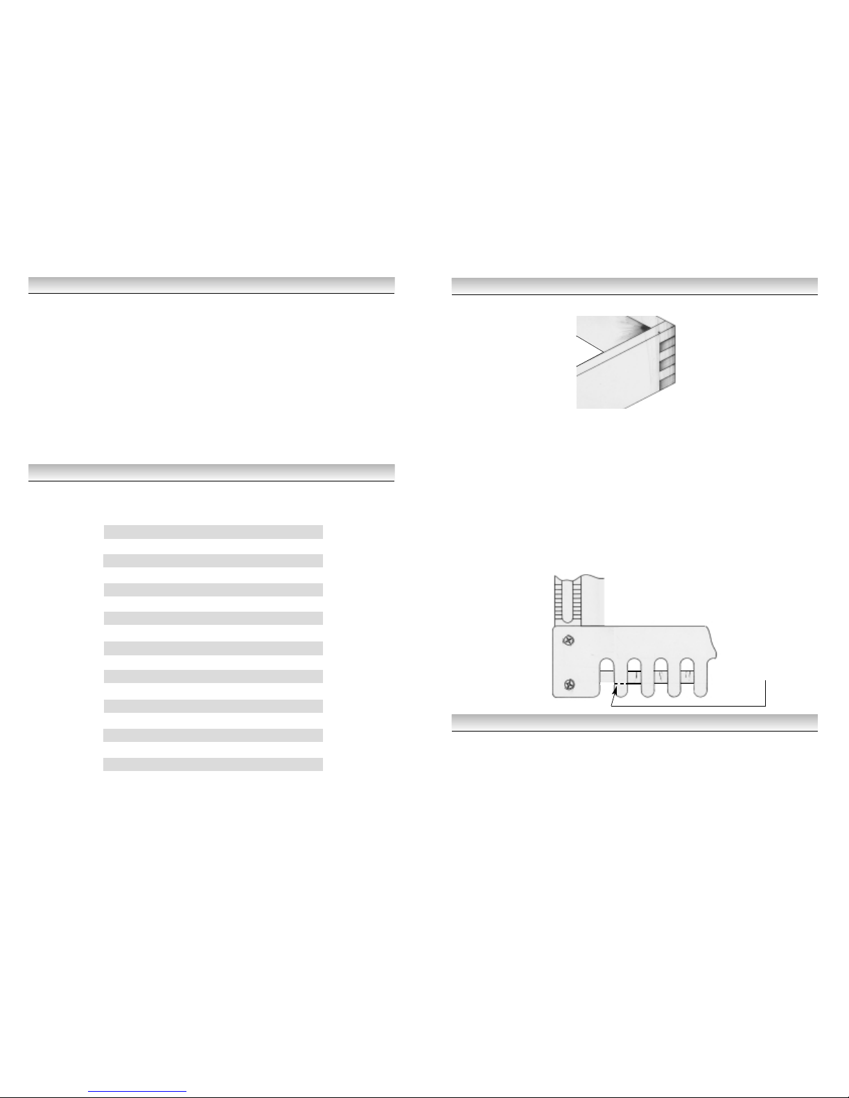
soon be producing accurate and good looking stopped or lapped dovetail joints without the need
for time consuming and laborious hand work. This type of dovetail gives a clean smooth interior
to the box or drawer with a neat craftsman - like joint showing on the outside.
A little time spent now getting to know your jig and establishing the correct settings will pay
dividends in the future. Once adjusted to the thickness of your timber the cam action clamping
system is a quick, one lever operation enabling fast alignment of work and a secure hold during
machining.
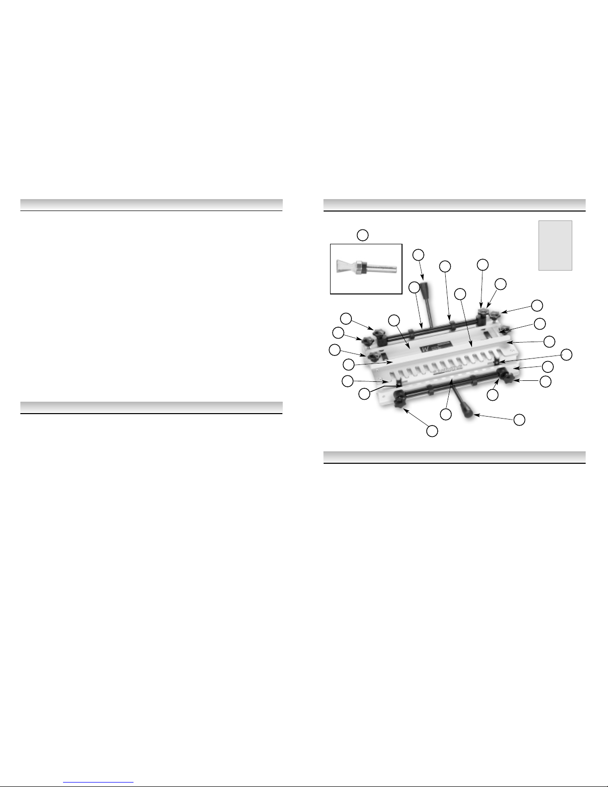
Illustration and Parts Description of Dovetail Jig
7. Cutting the Joint
Because there may be a need to alter one or more of the settings in order to get the joint to fit
correctly it is wiser to carry out the initial cuts on two trial pieces of timber of the same width and
thickness as the final components.
Position the router on the template with the cutter clear of the timber and switch on.
Now with just a light cut run the router from right to left across the work, just touching the end of
each finger. Continue the cut allowing the router to do the work and avoiding any heavy-handed
forced contact with the template. Follow the template in and out of the finger guides working from
left to right. When completed switch the router off before lifting it from the jig.
Remove the pieces from the jig, make a trial fit and then, if necessary, make the following
adjustments:
• If the fit is too loose, increase the cutter depth by 0.5mm.
• If the fit is too tight, decrease the cutter depth by 0.5mm.
• If the pins stand proud of the joint, move the back stop further back.
• If the pins sit too deep in the joint, move the back stop further forward.
Having made the necessary adjustments you can either make a second trial cut or proceed
directly to the final joint. Once the correct settings have been made then production runs of joints
can be undertaken, although the settings will need to be checked periodically to maintain
accuracy.
Fig 1
22
4
4
9
3
1
11
7
7
7
10
2
5
24
8
14
2
7
16
17
13
9
5
13 A
8. Box Jointing
Box joints can be formed in timber with a maximum thickness of 3/4
"
using a 1/2
"
diameter
bearing guided cutter, Stock No P152006A. The procedure is different from that used for
dovetailing in that both boards are mounted vertically in the front clamp and cut independently of
each other with the fingers in one board offset by 1/2
"
from those on the other.
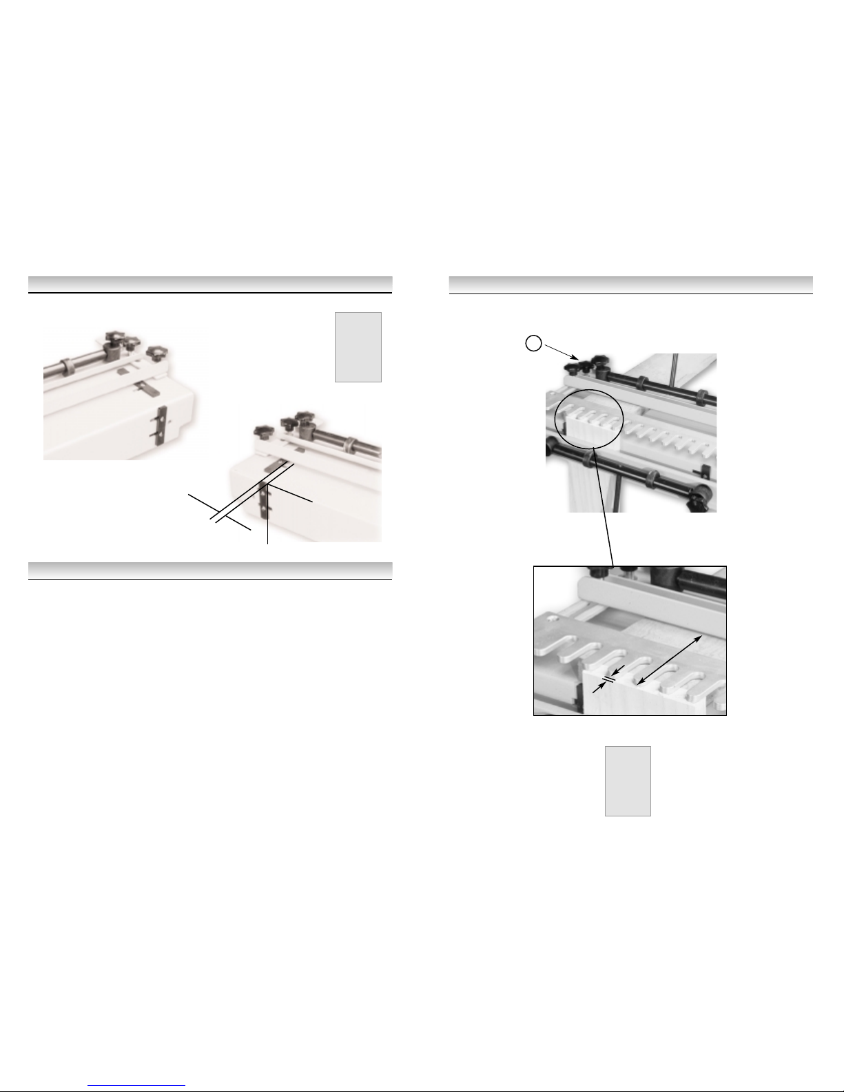
First of all, the template assembly needs to be brought forward as far as possible and locked in
position with the locking knobs (4) see Fig 5; this will allow the cutter to move far enough in the
fingers to cut the full 3/4
"
thickness of timber. Next, the template assembly should be raised high
enough to allow the cutter to cut to its full depth without fouling the top surface of the jig body.
This can be achieved by placing a timber spacer (or spacers) underneath both the rear clamp
and the template and locking in position with the rear clamp. The spacer should be at least 1/8
"
(3mm) thicker than the timber being jointed which should be enough to ensure that the cutter
will cut the full depth without contacting the body of the jig.
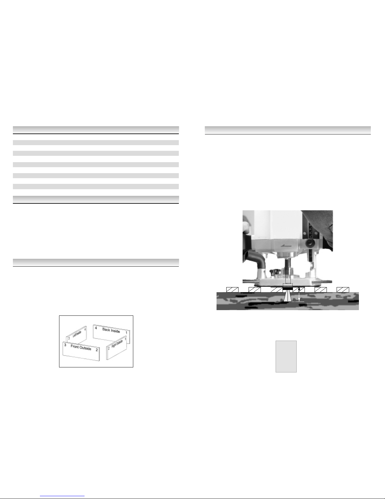
The depth of the cutter below the router base plate should be set to give the required joint depth
plus the thickness of the template (e.g. 19 + 6 = 25mm in the case of 3/4
"
timber). It is important
to note that when thinner timber is used the guide bearing will sit higher up in the template and in
this case it may be necessary to position the timber below the bottom of the template (with the
aid of a thin plywood shim) so that the bearing still runs within the depth of the template.
WHITE
AXMINSTER
W