manuals.online logo
Brands
  1. Home
  2. •
  3. Brands
  4. •
  5. Axxess
  6. •
  7. Recording Equipment
  8. •
  9. Axxess BX-GM7 User manual

Axxess BX-GM7 User manual

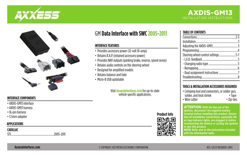
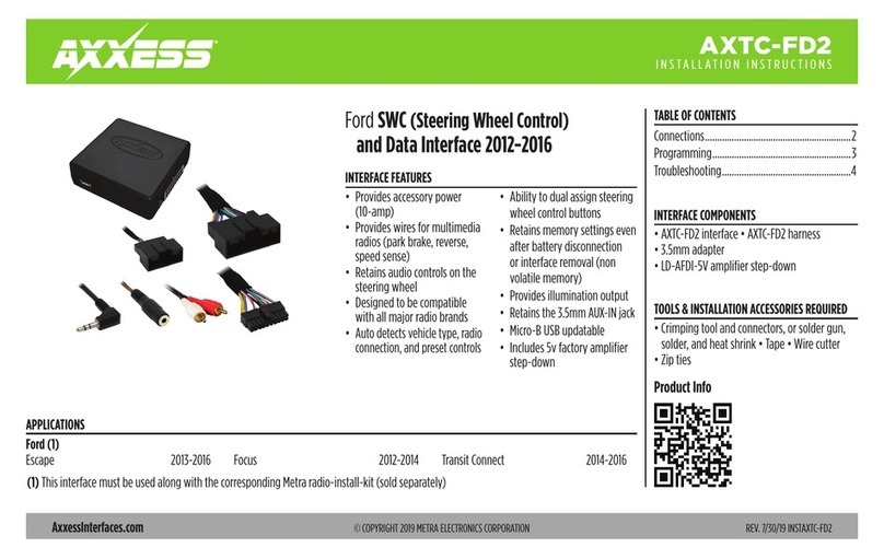
Installation instructions for BX-GM7
REV. 6/5/2015 INSTBX-GM7
(continued on next page)
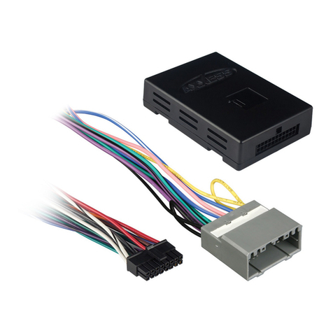
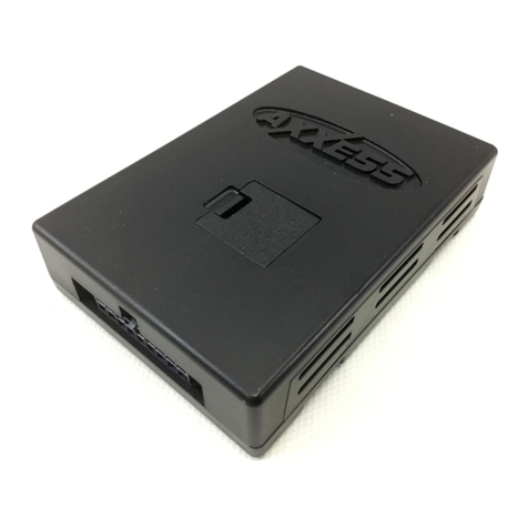
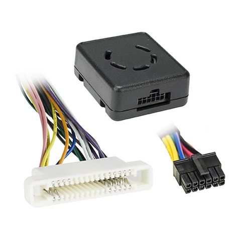
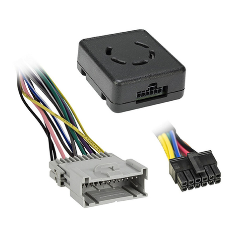
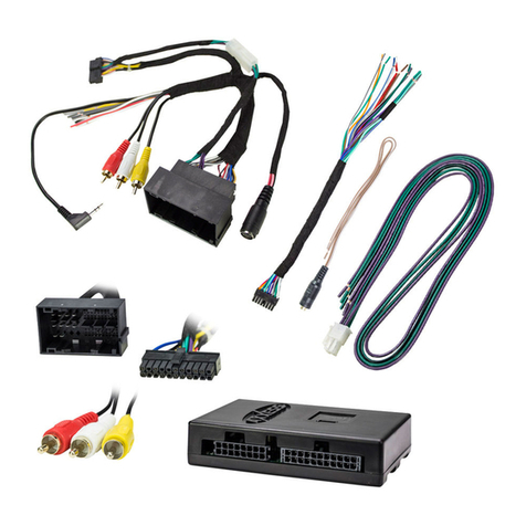
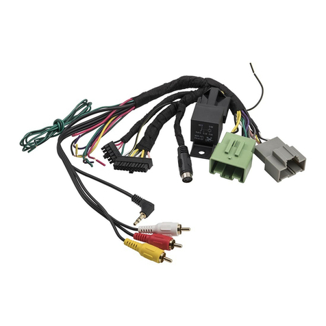
INTERFACE COMPONENTS
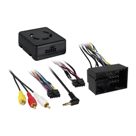
• BX-GM7 interface • GM7 24-pin to 4-pin harness
• GM3 30-pin to 4-pin harness
APPLICATIONS
FEATURES
BX-GM7
GM 11-bit LAN data interface
2004-2012
TOOLS REQUIRED
• Cutting tool • Tape • Crimping tool
• Connectors (i.e. butt-connectors, bell caps, etc.)
Caution: Metra recommends disconnecting the negative battery terminal before
beginning any installation. All accessories, switches, and especially air bag indicator
lights must be plugged in before reconnecting the battery or cycling the ignition.
*Note: Refer also to the instructions included with the aftermarket radio.
Connections to be made
From the GM7 24-pin to 4-pin harness, to the aftermarket radio
• Connect the Black wire to the ground wire.
• Connect the Yellow wire to the battery wire.
• Connect the Red wire to the accessory wire.
• Connect the Blue wire to the amp turn-on wire.
Note: This wire must be connected to hear sound from the factory amplifier, if applicable.
• Connect the White wire to the left front positive speaker output.
• Connect the White/Black wire to the left front negative speaker output.
• Connect the Gray wire to the right front positive speaker output.
• Connect the Gray/Black wire to the right front negative speaker output.
• Connect the Green wire to the left rear positive speaker output.
• Connect the Green/Black wire to the left rear negative speaker output.
• Connect the Purple wire to the right rear positive speaker output.
• Connect the Purple/Black wire to the right rear negative speaker output.
From the GM3 30-pin to 4-pin harness, to the aftermarket radio
• Connect the Black wire to the ground wire.
• Connect the Yellow wire to the battery wire.
• Connect the Red wire to the accessory wire.
• Provides accessory power
(12-volt 10-amp)
• Retains R.A.P. (retained
accessory power)
• Retains chimes through an
onboard speaker
• Prewired ASWC-1 harness
included (ASWC-1 sold separately)
• Can be used in non-amplified
or amplified models
• High level speaker input
• Retains balance and fade
• Low profile case
• USB updatable
CHEVROLET
Cobalt** 2007-2010
Cobalt* 2005-2006
HHR** 2006-2011
Equinox* 2005-2006
Malibu** 2008-2012
Malibu* 2004-2007
Malibu Classic* 2008
Malibu Maxx* 2004-2007
PONTIAC
G6** 2010
G6** (5th digit of VIN must be a J, K, or L) 2009
PONTIAC (continued)
G6* (5th digit of VIN must be a G, H or M) 2009
G6* 2005-2008
G5** 2007-2009
Solstice** 2006-2009
Torrent* 2006
SATURN
Aura** 2007-2009
Sky** 2007-2009
*GM7 24-pin to 4-pin harness applications
**GM3 30-pin to 4-pin harness applications
BX-GM7
REV. 6/5/2015 INSTBX-GM7
IMPORTANT WARNING
This product includes instructions for installation which must be carefully followed. The
instructions are worded in such a manner to assume that the installer is capable of completing
these type of electronic installations. If you are unclear as to what you are instructed to do or
believe that you do not understand the instructions so as to properly and safely complete the
installation you should consult a technician who does have this knowledge and understanding.
• Connect the Blue/White wire to the amp turn-on wire. Note: This wire must
be connected to hear sound from the factory amplifier, if applicable.
• Connect the Orange wire to the illumination wire. Note: If the aftermarket
radio has no illumination wire, tape off and disregard this wire.
• Connect the White wire to the left front positive speaker output.
• Connect the White/Black wire to the left front negative speaker output.
• Connect the Gray wire to the right front positive speaker output.
• Connect the Gray/Black wire to the right front negative speaker output.
• Connect the Green wire to the left rear positive speaker output.
• Connect the Green/Black wire to the left rear negative speaker output.
• Connect the Purple wire to the right rear positive speaker output.
• Connect the Purple/Black wire to the right rear negative speaker output.
12-pin pre-wired ASWC-1 harness
•
This harness is to be used along with the optional ASWC-1 (not included) to
retain steering wheel audio controls. If the ASWC-1 is not being used, disregard
this harness. If it will be used, please proceed onto the following instructions.
Also, refer to the ASWC-1 instructions for radio connections and programming.
• The following wire(s) must be cut before programming the ASWC-1. If your
vehicle is not listed, do not cut any wire(s):
For the following GM7 applications,
cut the Green/Orange wire:
Chevrolet
Malibu
(with a 3-spoke
steering wheel)
............... 2004-2007
Malibu Maxx
(with a 3-spoke
steering wheel)
............... 2004-2007
For the following GM7 applications,
cut the Green/Orange and White/
Green wires:
Chevrolet
Cobalt .......................... 2005-2006
Malibu
(with a 4-spoke
steering wheel)
............... 2004-2007
Malibu Maxx
(with a 4-spoke
steering wheel)
............... 2004-2007
For the following GM3 applications,
cut the Green/Orange wire:
Chevrolet
HHR .............................. 2006-2009
Malibu .......................... 2008-2012
Pontiac
G5 ................................ 2007-2009
G6 ................................ 2009-2010
Solstice ........................ 2006-2009
Saturn
Aura ............................. 2007-2009
Sky ............................... 2007-2009
Note: Disregard the harness that comes
with the ASWC-1.
Installing the BX-GM7
With the key in the off position
• Depending on your application, connect either the GM7 24-pin to 4-pin
harness, or GM3 30-pin to 4-pin harness, into the BX-GM7 interface.
• Depending on your application, connect either the GM7 24-pin to 4-pin
harness, or GM3 30-pin to 4-pin harness, into the vehicle.
• With all connections completed, reconnect the negative battery terminal.
Initializing the BX-GM7
Attention: If the BX-GM7 loses power for any reason, the following step will
need to be performed again.
• Initialize the interface by turning the ignition on for 30 seconds, then turn
the ignition back off, then back on again.
Note: If using the ASWC-1, connect it after you initialize the BX-GM7, with
the key in the off position.
Other Axxess Recording Equipment manuals

Axxess AXDIS-FD3 User manual

Axxess

Axxess AXDIS-FD3 User manual

Axxess GMOS-LAN-10 User manual

Axxess

Axxess GMOS-LAN-10 User manual

Axxess ASWC-1 User manual

Axxess

Axxess ASWC-1 User manual

Axxess CHTO-02 User manual

Axxess

Axxess CHTO-02 User manual

Axxess AXDSPL-GM31 User manual

Axxess

Axxess AXDSPL-GM31 User manual

Axxess GMOS-09 User manual

Axxess

Axxess GMOS-09 User manual

Axxess CHTO-02 User manual

Axxess

Axxess CHTO-02 User manual

Axxess AXDSPL-HN1 User manual

Axxess

Axxess AXDSPL-HN1 User manual

Axxess AXAC-FD1 User manual

Axxess

Axxess AXAC-FD1 User manual

Axxess AXTC-VW1 User manual

Axxess

Axxess AXTC-VW1 User manual

Axxess GMOS-08 User manual

Axxess

Axxess GMOS-08 User manual

Axxess BX-GM6 User manual

Axxess

Axxess BX-GM6 User manual

Axxess LC-GMRC-05 User manual

Axxess

Axxess LC-GMRC-05 User manual

Axxess GMOS-LAN-03 User manual

Axxess

Axxess GMOS-LAN-03 User manual

Axxess AXDSPX-BM1 User manual

Axxess

Axxess AXDSPX-BM1 User manual

Axxess AXi-CANBOX1 User manual

Axxess

Axxess AXi-CANBOX1 User manual

Axxess AXDSPX-GM30 User manual

Axxess

Axxess AXDSPX-GM30 User manual

Axxess XSVI-9004-NAV User manual

Axxess

Axxess XSVI-9004-NAV User manual

Axxess AXDSPL-BM1 User manual

Axxess

Axxess AXDSPL-BM1 User manual

Axxess XSVI-9006-NAV User manual

Axxess

Axxess XSVI-9006-NAV User manual

Axxess GMOS-04 User manual

Axxess

Axxess GMOS-04 User manual

Axxess GMOS-LAN-09 User manual

Axxess

Axxess GMOS-LAN-09 User manual

Axxess GMOS-LAN-01 User manual

Axxess

Axxess GMOS-LAN-01 User manual

Axxess GMOS-LAN-09 User manual

Axxess

Axxess GMOS-LAN-09 User manual

Popular Recording Equipment manuals by other brands

Marantz PMD620 user guide

Marantz

Marantz PMD620 user guide

HMS Anybus X-gateway IIoT Startup guide

HMS

HMS Anybus X-gateway IIoT Startup guide

Roland CD-2u owner's manual

Roland

Roland CD-2u owner's manual

r.LiNK RL4-MM-NP manual

r.LiNK

r.LiNK RL4-MM-NP manual

MINDPRINT T.R.I.O. manual 

MINDPRINT

MINDPRINT T.R.I.O. manual 

X10 HC60RX install guide

X10

X10 HC60RX install guide

Xylem YSI ProDSS user manual

Xylem

Xylem YSI ProDSS user manual

DOREMIDI FC-3 instructions

DOREMIDI

DOREMIDI FC-3 instructions

Emerson QuickPanel+ IC755C S06RD Series quick start guide

Emerson

Emerson QuickPanel+ IC755C S06RD Series quick start guide

Dytran ENIDINE ENI-VIBE 33VC4400B quick start guide

Dytran

Dytran ENIDINE ENI-VIBE 33VC4400B quick start guide

Oticon Medical Neuro 2 Swim Kit Quick reference guide

Oticon Medical

Oticon Medical Neuro 2 Swim Kit Quick reference guide

Yamaha VL1-m Feature reference

Yamaha

Yamaha VL1-m Feature reference

Squarp Instruments Hermod+ quick start

Squarp Instruments

Squarp Instruments Hermod+ quick start

Korg ToneWorks AX3000G owner's manual

Korg

Korg ToneWorks AX3000G owner's manual

Panasonic AJSPD850P - P2 DECK operating instructions

Panasonic

Panasonic AJSPD850P - P2 DECK operating instructions

herdstar BinTrac RM200B Installation and operation manual

herdstar

herdstar BinTrac RM200B Installation and operation manual

Campbell SC-USB instruction manual

Campbell

Campbell SC-USB instruction manual

Pepperl+Fuchs IRI-KHD2-4HB5 manual

Pepperl+Fuchs

Pepperl+Fuchs IRI-KHD2-4HB5 manual

manuals.online logo
manuals.online logoBrands
  • About & Mission
  • Contact us
  • Privacy Policy
  • Terms and Conditions

Copyright 2025 Manuals.Online. All Rights Reserved.