Axxess GMOS-LAN-01 User manual

GM ONSTAR LAN DATA BUS INTERFACE
GMOS-LAN-01
Installation Inst uctions
877-312-4547
© COPYRIGHT 2004-2010 METRA ELECTRONICS CORPORATION Rev. 12-1-10
www.solidsignal.com
APPLICATIONS
Not com atible with am lified sound systems
* READ IMPORTANT WARNING ON PAGE 1
BEFORE ATTEMPTING ANY INSTALLATION
The GMOS-LAN-01 is
designed to retain Onstar and retain the warning
chimes that are normally lost when the OEM radio is removed. It
also provides a 12 volt accessory output or proper a termarket
radio operation. THE GMOS-LAN-01 also PROVIDES a MUTE,
PARKING BRAKE, VSS OR SPEED SENSE, AND A REVERSE OUT-
PUT TO MAKE INSTALLING AN AFTERMARKET NAVIGATIONAL
RADIO SIMPLER AND LESS TIME CONSUMING.
Buick
• Enclave 2007-11
• Lucerne 2006-10
Cadillac
• DTS 2006-10
• SRX 2007-09
Chevrolet
• Avalanche 2007-10
• Aveo 2009-10 *
• Equinox 2007-09
• Express 2008-10
• Impala 2006-10
• Monte Carlo 2006-07
• Silverado (new body)
2007-11
• Suburban 2007-10
• Tahoe 2007-11
• Traverse 2009-11
GMC
•Acadia 2007-11
•Savanna 2008-10
•Sierra ( ew body) 2007-11
•Yukon / XL 2007-10
Hummer
•H2 2008-09
Pontiac
•Torrent 2007-09
• Vibe 2010 *
*( Only required for retention of Onstar-
NA outputs not applicable)
Saturn
•Outlook 2007-09
•Vue 2008-09
Suzuki
•XL-7 2007-09
IN ERFACE COMPONEN S
• GMOS-LA -01 Interface
• 14 pin harness with stripped leads
• 12 pin to 30 pin GM harness

GMOS-LAN-01
1
* READ IMPORTANT WARNING
BEFORE ATTEMPTING ANY INSTALLATION
* IMPOR AN WARNING
THIS PRODUCT I CLUDES I STRUCTIO S FOR I STALLATIO WHICH
MUST BE CAREFULLY FOLLOWED. THE I STRUCTIO S ARE WORDED I
SUCH A MA ER TO ASSUME THAT THE I STALLER IS CAPABLE OF COM-
PLETI G THESE TYPE OF ELECTRO IC I STALLATIO S. IF YOU ARE
U CLEAR AS TO WHAT YOU ARE I STRUCTED TO DO OR BELIEVE THAT
YOU DO OT U DERSTA D THE I STRUCTIO S SO AS TO PROPERLY A D
SAFELY COMPLETE THE I STALLATIO YOU SHOULD CO SULT A TECH I-
CIA WHO DOES HAVE THIS K OWLEDGE A D U DERSTA DI G.
FAILURE TO FOLLO THESE INSTRUCTIONS CAREFULLY AND TO
INSTALL THE INTERFACE AS DESCRIBED COULD CAUSE HARM TO THE
VEHICLE OR TO SAFETY SYSTEMS ON THE VEHICLE. INTERFERENCE
ITH CERTAIN SAFETY SYSTEMS COULD CAUSE HARM TO PERSONS
AS ELL.
IF YOU HAVE ANY QUESTIONS IN THIS REGARD PLEASE CALL
SOLID SIGNAL AT 877.312.4547 FOR ASSISTANCE.
KNOWLEDGE IS POWER
Enhance your installation and fabrication skills by
enrolling in the most recognized and respected
mobile electronics school in our industry.
Log onto www.installerinstitute.com or call
800-354-6782 for more information and take steps
toward a better tomorrow.
We recommend MESA
certi ied technicians
We recommend MECP
certi ied technicians

GMOS-LAN-01
2
OOLS REQUIRED FOR INS ALLA ION
INS ALLING HE IN ERFACE
* Important: Before beginning any of the following, disconnect the negative battery terminal to prevent acci-
dental short circuit.
FOR INS ALLA ION OF AF ERMARKE RADIO ONLY:
From the 14 pin harness:
1.
Connect the red wire to the ignition/accessory wire of the aftermar et radio.
2.
Connect the orange wire to the illumination wire of the aftermar et radio. If the aftermar et
radio has no illumination wire just tape off the orange wire.
3.
Connect the Blue/wh te wire to the amp turn on wire of the aftermar et radio.
4.
Connect the wh te wire to the left front positive spea er output of the aftermar et radio.
5. Connect the wh te/black wire to the left front negative spea er output of the aftermar et radio.
6. Connect the gray wire to the right front positive spea er output of the aftermar et radio.
7. Connect the gray/black wire to the right front negative spea er output of the aftermar et radio.
8. Connect the brown wire to the mute wire of the aftermar et radio. If the after mar et radio does not have
a Mute wire, tape up the brown wire.
The follow ng w res on the 14 p n harness are for the aftermarket rad os that have nav gat on bu lt n:
1. Connect the green wire to the par ing bra e wire of the aftermar et navigation radio.
2. Connect the blue/p nk wire to the VSS or speed sense wire of the aftermar et navigation radio.
3. Connect the green/purple wire to the reverse wire of the aftermar et navigation radio.
From the 12 pin harness:
1.
Connect theYellow wire to the 12 volt constant/battery wire of the aftermarket radio.
2.
Connect the Black wire to the ground wire of the aftermarket radio.
3.
The Black/Yellow and Black/White wires will be discussed later in this manual.
From the 30 pin GM harness:
1.
Connect the Green wire to the left rear positive speaker output of the aftermarket radio.
2.
Connect the Green/Black wire to the left rear negative speaker output of the aftermarket radio.
3.
Connect the Purple wire to the right rear positive speaker output of the after-market radio.
4. Connect the Purple/Black wire to the right rear negative output of the aftermarket radio.
• Cutting Tool • Tape • Crimping Tool • Connectors (ie: butt-connectors, bell caps, etc.)
(See wiring diagram 1 on page 3

GMOS-LAN-01
3
BLK
RF-
GM
OS-LAN-01
RADIO
R
L
L
RF+
LF-
YEL
LF+
RED
DI
CHIME VOLUME
ADJUSTMENT
AGR
R
R+
L
R-
L
R+
7 WIRES
R
AM 1
BLACK/YELLOW
BLACK/WHITE
BLUE/WHITE
ORANGE
RR-
GM 30 PIN

GMOS-LAN-01
4
CONNEC IONS O BE MADE ON HE 14 PIN HARNESS:
1.
Connect the red wire to the ignition/accessory wire of the aftermar et radio.
2. Connect the Orange wire to the illumination wire of the aftermar et radio. If the aftermar et radio
has no illumination wire just tape off the orange wire.
3. Connect the blue/wh te wire to the amp turn on wire of the aftermar et radio and to the blue/wh te wire in
the 24 pin harness.
4. Wh te NOT USED
5. Wh te/black NOT USED
6. Gray NOT USED
7. Gray/black NOT USED
8. Connect the Brown wire to the mute wire of the aftermar et radio. If the after mar et radio does not have a
Mute wire, tape up the Brown wire.
The follow ng w res on the 14 p n harness are for the aftermarket rad os that have nav gat on bu lt n:
1. Connect the Green wire to the par ing bra e wire of the aftermar et navigation radio.
The follow ng w res on the 14 p n harness are for the aftermarket rad os that have nav gat on bu lt n:
2. Connect the Blue/Pink wire to the SS or speed sense wire of the aftermarket navigation radio.
3. Connect the Green/Purple wire to the reverse wire of the aftermarket navigation radio.
When completed, plug the 14 pin harness into the GMOS-LAN-01.
CONNEC IONS O BE MADE ON HE 30 PIN GM HARNESS:
1. Connect the green wire to the amplifier’s left rear positive speaker output.
2. Connect the the green/black wire to the amplifier’s left rear negative speaker output.
3. Connect the purple wire to the amplifier’s right rear positive speaker output.
4. Connect the purple/black wire to the amplifier’s right rear negative speaker output.
5. Cut the white wire about half way between the two plugs. Connect the white wire from the 24 pin plug to
amplifier’s left front positive speaker output wire. Connect the white wire from the 12 pin plug to the positive
speaker wire of the Metra SP-2003 or equivalent.
6. Cut the white/black wire about half way between the two plugs. Connect the white/black wire from the 24
pin plug to amplifier’s left front negative speaker output wire. Connect the white/black wire from the 12 pin
plug to the negative speaker wire of the Metra SP-2003 or equivalent.
FOR AF ERMARKE RADIO AND AMPLIFIER
(See wiring diagram on page 6)

GMOS-LAN-01
5
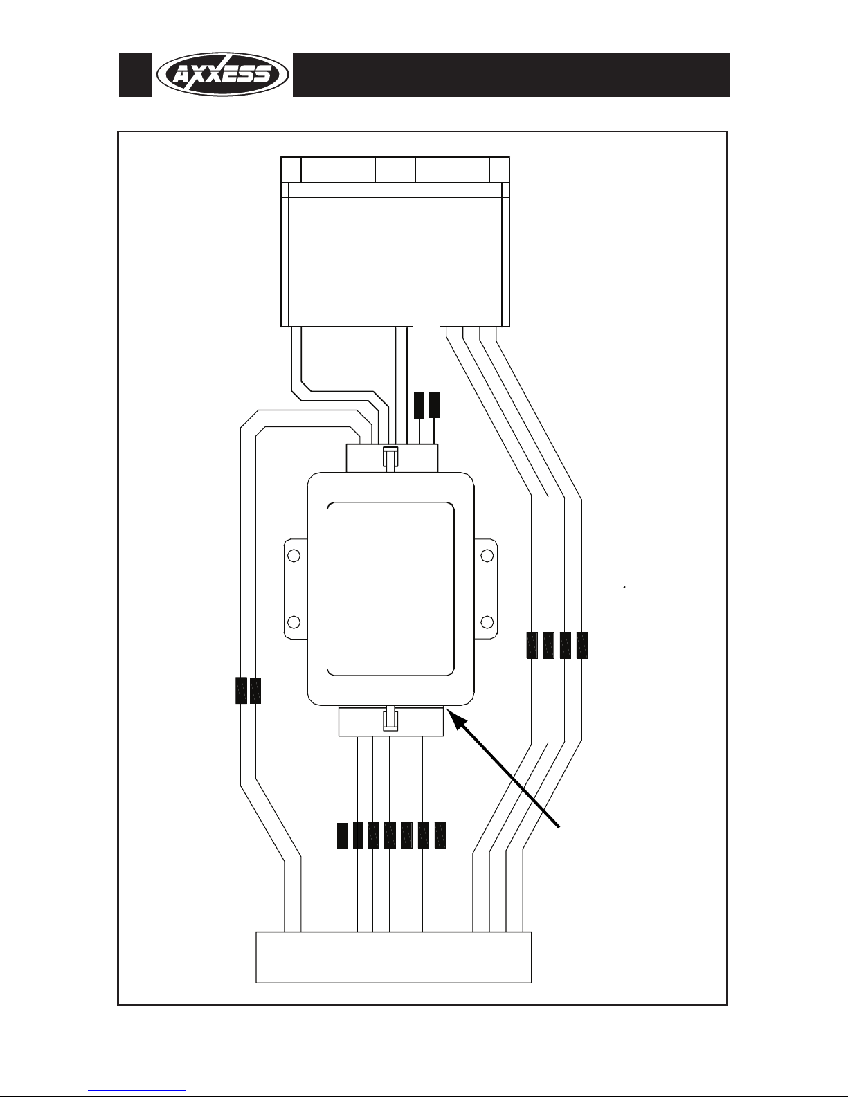
7. Cut the gray wire about half way between the two plugs. Connect the gray wire from the 24 pin plug to ampli-
fier’s right front positive speaker output wire. Connect the gray wire from the 12 pin plug to the positive
speakerwire of the Metra SP-2003 or equivalent.
8. Cut the gray/black wire about half way between the two plugs. Connect the gray/black wire from the 24 pin
plug to amplifier’s right front negative speaker output wire. Connect the gray/black wire from the 12 pin plug
to the negative speaker wire of the Metra SP-2003 or equivalent.
Note: I only one SP-2003 is used tape up the gray wires that would normally connect to the second
SP-2003 to avoid a short circuit.
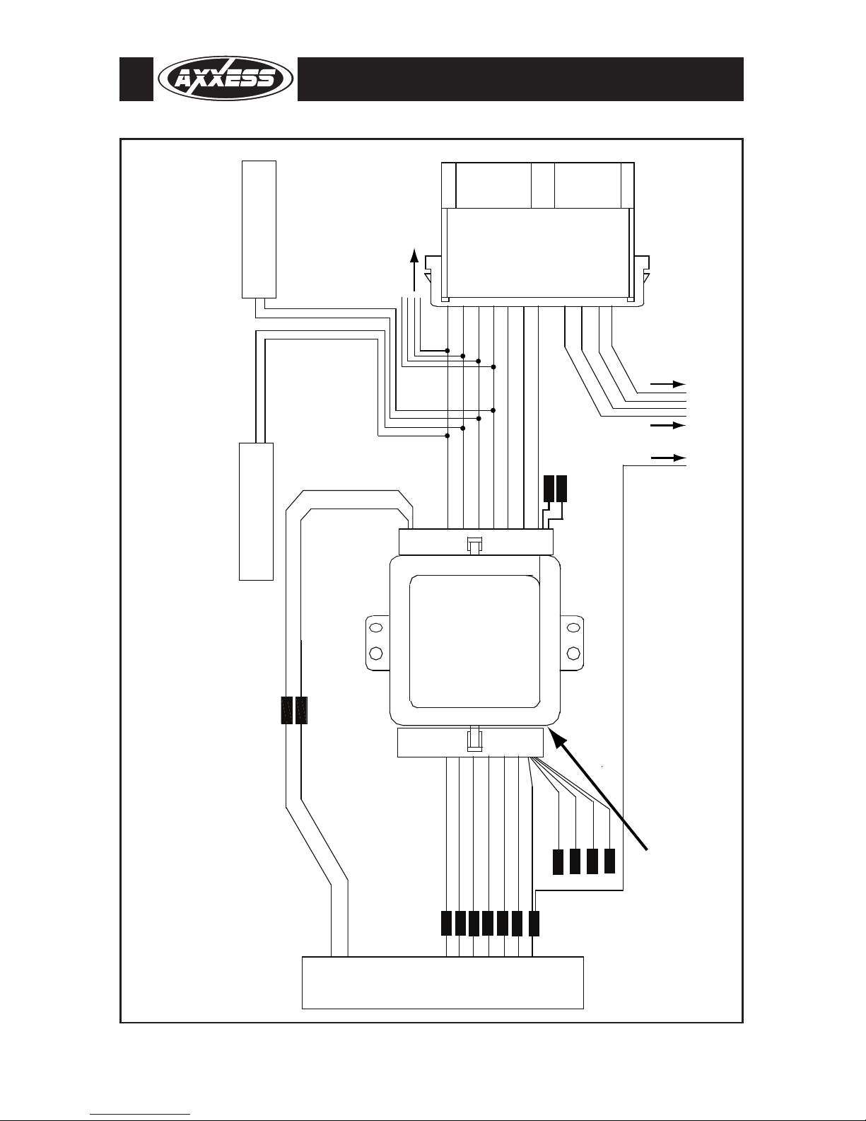
CONNEC IONS O BE MADE ON HE 12 PIN HARNESS:
1. Connect the yellow wire to the radio’s 12 volt battery or memory wire.
2. Connect the black wire to the radio’s ground wire.
3. The black/yellow and black/white wire is for the Onstar volume adjustment. This will be discussed in the
Onstar and Chime Level Adjustment section of this instruction.
When completed, plug the 12 pin harness into the GMOS-LAN-01.
FINAL WIRING CONNEC IONS
Make wiring connections using the EIA color code chart shown below and the
instructions included with the head unit. Metra recommends making connec-
tions as shown below; Strip, Splice, Solder, Tape. Isolate and individually tape
off ends of any unused wires to prevent electrical short circuit.
STRIP
SPLICE
SOLDER
TAPE
ME RA/EIA WIRING CODE
12V Ignition / Acc. . . . . . . . . . Red
12V Batt / Memory. . . . . . . . . Yellow
Ground. . . . . . . . . . . . . . . . . . Black*
Power Antenna. . . . . . . . . . . . Blue
Amp Turn-On . . . . . . . . . . . . . Blue / White
Amp Ground. . . . . . . . . . . . . . Black / White
Illumination . . . . . . . . . . . . . . Orange
Dimmer . . . . . . . . . . . . . . . . . Orange / White
Right Front (+) . . . . . . . . . . . . Gray
Right Front (-). . . . . . . . . . . . . Gray / Black
Left Front (+) . . . . . . . . . . . . . White
Left Front (-). . . . . . . . . . . . . . White / Black
Right Rear (+) . . . . . . . . . . . . Violet
Right Rear (-) . . . . . . . . . . . . . Violet / Black
Left Rear (+) . . . . . . . . . . . . . Green
Left Rear (-) . . . . . . . . . . . . . . Green / Black

BLK
RADIO
YEL
AFTERMARKET RADIO AND AMPLIFIER WIRING
SP-2003
SP-2003
OPTIONAL
REQUIRED
GM
OS-LAN-01
RF
RF
LF
LF
-
+
-
+
CHIME VOLUME
ADJUSTMENT
RED
GREEN
BLUE/PINK
BLUE/WHITE
GREEN/PURPLE
BROWN
ORANGE/WHITE
14 PIN
12 PIN
RR-
RR+
LR-
LLR+
GM 30 PIN
TO AFTERMARKET
REAR AMPLIFIER
TO AFTERMARKET
FRONT AMPLIFIER
RF
RF
LF
LF
-
+
-
+
X
X
X
X
BLACK/YELLOW
BLACK/WHITE
GMOS-LAN-01
6

CHIME VOLUME ADJUS MEN
To adjust the chime volume, use a small screwdriver to rotate the potentiometer, located on the 14 pin harness side
of the interface, clockwise to make the chime louder and counterclockwise to make the chime softer.
ONS AR LEVEL ADJUS MEN
To adjust the Onstar volume level find the Black/Yellow wire on the 12 pin harness. Push the blue Onstar button,
while the voice is speaking tap the Black/Yellow wire to ground. There are 4 volume settings for Onstar; once the
4th setting is reached and the Black/Yellow wire is tapped to ground it will automatically go back to the first vol-
ume setting. Once the volume is set it will stay at that volume until the Black/Yellow wire is tapped to ground
again. This can be set during installation and then left alone. If user adjustment is desired, a momentary contact
switch (sold separately) can be added. Connect one terminal from the switch to ground and the other terminal to the
Black/Yellow wire. The volume will change one level every time the switch is pressed.
AUDIBLE URN SIGNAL
When the factory radio is removed the audible turn signal indicator is lost.
If that turn signal “clicking” is desired follow these steps:
1. Using a SPDT relay (Metra part # E-123), connect pin #85 to the Black/White wire in the 12 pin harness.
2. . Connect pin #86 to the 12 volt constant wire on the 12 pin harness.
3 . Be sure to cover the other leads of the relay by either using female spade connectors or using tape to cover
the leads.
Now when the turn signal is on, the relay will make the audible “clicking” noise.
INS ALLING HE GMOS-LAN-01
1.
With all connections completed,
plug the 14 and 12 pin harnesses into the GMOS-LA -01.
2. Reconnect the negative battery terminal.
3. Plug the 30 pin GM harness into the vehicle side harness, and plug the aftermarket radio harness into the
aftermarket radio.
4. Cycle the key by turning the ignition on then back off, then back on again to test the radio.
ES ING HE GMOS-LAN-01
1. Turn the ignition on, and then turn the aftermarket radio on.
2. Push the Onstar button, the radio should turn off and you should hear Onstar. Push the Onstar cancel button
and the radio should come back on.
GMOS-LAN-01
7
877.312.4547
REV. 12/1/10 © COPYRIGHT 2004-2009 METRA ELECTRONICS CORPORATION INSTGMOS-LAN-01
www.solidsignal.com
Table of contents
Other Axxess Recording Equipment manuals

Axxess
Axxess XSVI-9004-NAV User manual

Axxess
Axxess AX-AM-AU96 User manual

Axxess
Axxess CHTO-02 User manual

Axxess
Axxess AXDIS-FD3 User manual

Axxess
Axxess BX-GM7 User manual

Axxess
Axxess AXDSPL-HN1 User manual

Axxess
Axxess AX-AM-AU94 User manual

Axxess
Axxess XSVI-9006-NAV User manual

Axxess
Axxess TYTO-02 User manual

Axxess
Axxess AX-DSP-A2B1 User manual

Axxess
Axxess AX-CH013-SWC User manual

Axxess
Axxess ASWC-1 User manual

Axxess
Axxess AXTC-FD2 User manual

Axxess
Axxess MITO-03 User manual

Axxess
Axxess AX-FD1-SWC User manual

Axxess
Axxess AXi-CANBOX1 User manual

Axxess
Axxess AX-CH5-SWC User manual

Axxess
Axxess GMOS-04 User manual

Axxess
Axxess AXDSPL-GM31 User manual

Axxess
Axxess AXDSPL-BM1 User manual