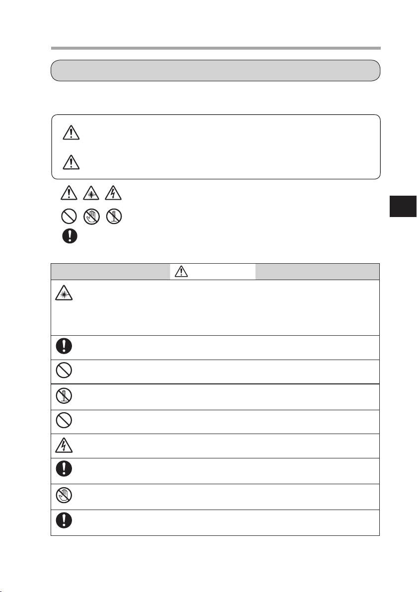
Azbil K1G Series User manual

No. CP-SP-1385E
K1G Series High-Accuracy Position Sensor
User's Manual
There are nine different manuals related to the K1G
series. Read them as necessary for your specific
requirements. ( P. iii )
This user's manual is for instrumentation that uses the K1G
series' K1G-C04, K1G-C04M, and K1G-C04E controllers.
For CE- and KC-marked K1G-C04G, K1G-C04MG, and K1G-
C04EG controllers, please refer to
K1G Series High-Accuracy
Position Sensor Global Model User's Manual (CP-SP-1397E)
.
INTRODUCTION
WHAT TO KNOW BEFORE USE
INSTALLATION AND WIRING
INITIAL SETUP
ADVANCED SETTINGS
SZD01 CONFIGURATION TOOL
SPECIFICATIONS
TROUBLE SHOOTING
APPENDIX
1
2
3
4
5
6
7
8
9
COMMUNICATION SETTINGS
CONNECTION TO OTHER DEVICES
Photo of K1G-S07
Photo of K1G-C04

NOTICE
Be sure that the user receives this manual before the product is used.
Copying or duplicating this user’s manual in part or in whole is forbidden.
The information and specifications in this manual are subject to change
without notice.
Considerable effort has been made to ensure that this manual is free from
inaccuracies and omissions. If you should find an error or omission, please
contact the azbil Group.
In no event is Azbil Corporation liable to anyone for any indirect, special or
consequential damages as a result of using this product.
© 2015-2018 Azbil Corporation All Rights Reserved.
ModbusTM is a trademark and the property of Schneider Electric SE, its subsidiaries
and affiliated companies.
EtherCAT® is a registered trademark and patented technology, licensed by
Beckhoff Automation GmbH, Germany.
Please read “Terms and Conditions” from the following URL before
ordering and use.
http://www.azbil.com/products/factory/order.html

i
The safety precautions explained in the following section aim to prevent injury to the
operator and others, and to prevent property damage.
: Use caution when handling the product.
: The indicated action is prohibited.
: Always follow the indicated instructions.
WARNING
This device is a JIS class 1 laser product. As this device's emitter uses a
semiconductor laser, observe the following cautions.
• Do not disassemble or modify sensor heads.
• Do not look into the laser beam directly.
• Do not look into the laser beam through a lens or other optical device.
Take sufficient safety measures to prevent damage or loss in the unlikely event
that this device malfunctions.
Do not use this device for safety circuits designed for protection of the human
body.
Do not disassemble.
Disassembly may cause electric shock or device failure.
Do not use this device in atmospheres containing corrosive or flammable gas,
liquids, or powder.
Before removing, mounting, or wiring this device, be sure to turn off the power to
the device and all connected devices. Failure to do so may cause electric shock.
Be sure to check that the device has been correctly wired before turning on the
power. Incorrect wiring of the module can damage it or lead to hazardous conditions.
Do not touch electrically charged parts such as the power terminals. There is a
risk of electric shock.
Firmly tighten the terminal screws to a torque of 0.4–0.6N·m.
If tightening is insufficient there is a risk of electric shock or fire.
SAFETY PRECAUTIONS
WARNING Warnings are indicated when mishandling this product
might result in death or serious injury.
CAUTION
Cautions are indicated when mishandling this product might result
in minor injury to the user, or physical damage to the product.

ii
WARNING
Do not use unused terminals on the device as relay terminals. Doing so may re-
sult in electric shock, fire or device failure.
In the following cases, turn off the power immediately and stop using the device.
• If the device gets wet (with water or another liquid).
• If the device is damaged.
• If the device produces an unusual smell or smoke.
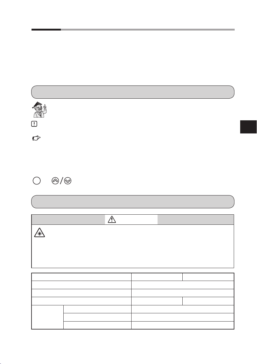
CAUTION
The power supply rating for this device is 12–24V DC. Do not apply 100–240V AC.
Doing so may cause device failure or fire.
Use this device within the operating ranges given in the specifications for
temperature, humidity, voltage, vibration, shock, mounting orientation, atmo-
sphere, etc. Otherwise, fire or device failure could result.
Do not block ventilation holes.
Doing so may cause fire or device failure.
Wire this device properly, according to the directions, using the specified power
source and wiring methods.
Failure to do so may cause fire or device failure.
Do not allow wire clippings, metal shavings, water, etc., to enter the device's case.
They may cause fire or device failure.
If there is a risk of a power surge caused by lightning, use a surge absorber
(surge protector).
Failure to do so may cause fire or device failure.
When discarding this device, dispose of it as industrial waste, following local
regulations.
At the time of disposal, do not allow the optical surfaces to be exposed to direct
sunlight in order to prevent concentration of the sunlight, which could cause a fire.
Do not try to modify or fabricate the connectors and junction cable.
Doing so may cause device failure, abnormal laser beam emission, or fire.
Take care that cables are not pinched or caught on something.
There is a danger of disconnection.
Connect the controller’s frame ground terminals to the ground (for K1G-C04M,
that includes the frame ground for MECHATROLINK-III, and for K1G-C04E it in-
cludes the frame ground for EtherCAT). If the terminals are not grounded, electro-
magnetic interference may result.

iii
THE ROLE OF THIS MANUAL
A total of 9 different manuals are available for the K1G series. Read them as necessary for
your specific requirements.
If a manual you require is not available, contact the Azbil Group or its dealer.
K1G Series High-Accuracy Position Sensor User's Manual
Manual No. CP-SP-1385E
This manual describes the hardware and all functions of the K1G.
Personnel in charge of the design, manufacture, operation, or maintenance
of equipment that incorporates this device, or the design of communica-
tion software for equipment that uses this device's serial communication
function, should read this manual thoroughly.
K1G Series High-Accuracy Position Sensor Global Model
User's Manual Manual No. CP-SP-1397E
If you need to use a CE- or KC-marked K1G controller, please purchase the
K1G-C04G or the K1G-C04MG or the K1G-C04EG and read this manual.
K1G Series High-Accuracy Position Sensor
MECHATROLINK-III Communication Manual
Manual No. CP-SP-1386E
This manual describes the MECHATROLINK-III communication specifica-
tions.
K1G Series High-Accuracy Position Sensor User's Manual
for EtherCAT Communication
Manual No. CP-SP-1419E
This manual describes EtherCAT communications specifications.
K1G Series High-Accuracy Position Sensor Controller User's Manual
Manual No. CP-UM-5783JE
Personnel in charge of the design or manufacture of equipment that incor-
porates this device should read this manual thoroughly. The manual covers
safety precautions, installation, wiring, and primary specifications.
K1G Series High-Accuracy Position Sensor Head User's Manual
Manual No. UM-5784JE
Personnel in charge of the design or manufacture of equipment that in-
corporates the sensor heads should read this manual thoroughly. It covers
safety precautions, installation, wiring, and primary specifications.

iv
Handling Precautions for the SZ-D01 Configuration Tool
for K1G Series High-Accuracy Position Sensors
Manual No. UM-5785JE
Personnel who use the configuration tool for K1G sensors should read this
manual. The manual covers safety precautions, installation, and wiring.
Handling Precautions for K1G Series High-Accuracy Position
Sensor Junction Cables
Manual No. UM-5787JE
Personnel in charge of the design or manufacture of equipment that in-
corporates these cables should read this document thoroughly. It contains
safety precautions.
Attachment Instructions for Ferrite Core and Shielded
Junction Cables for K1G Series High-Accuracy Position Sensors
Manual No. CP-UM-5810JE
Please read this manual if you use a CE- or KC-marked global model of the
K1G series. This manual covers safety precautions, installation, and wiring.

v
Introduction
Thank you for purchasing this Azbil Corporation product. This manual contains informa-
tion for ensuring the safe and correct use of the product.
It should be read by those who design or maintain a control panel or other equipment
that uses this product.
Also, the manual provides necessary information for installation, maintenance, and trou-
bleshooting. Be sure to keep the manual nearby for handy reference.
CONVENTIONS USED IN THIS MANUAL
: Indicates a tip for configuration or operation.
Handling Precautions : Pay attention to the indicated points when handling the
product.
: Refer to the indicated item or page.
1 2 3 : Numbers indicate steps in a procedure.
8888 :This font indicates what is shown on the 7-segment display.
Para
: Keys on the operating panel
WARNING
This set of sensor heads is a class 1 laser product using a semiconductor laser as
the light source.
For this reason, note the following.
• Do not disassemble or modify sensor heads.
• Do not look into the laser beam directly.
• Do not look into the laser beam through a lens or other optical device.
Sensor head model No. K1G-S07 K1G-S15
Emission wavelength 650nm
Output Less than 0.39mW
Pulse width 25µs 100µs
Laser class JIS standards Class 1 laser product (JIS C)
IEC 60825-1 Class 1 Laser Product
FDA (CDRH) Part 1040.10 Class 1 Laser Product *
* Laser product classification by FDA (CDRH) is based on IEC 60825-1, in accordance with Laser
Notice No. 50.
NOTES ON LASERS
Introduction

vi
Introduction
HANDLING PRECAUTIONS
•As part of setup work or operation, check that this device is operating properly.
• If this device is used in combination with other devices, its functions and performance
may not meet specifications, depending on the operating conditions and environment.
Consider the combination carefully before use.
• If electromagnetic interference caused by this device affects other devices, use a
shielded junction cable. For details, contact the azbil Group.
INSTALLATION ENVIRONMENT
To ensure the safe and correct use of the product, do not install it where it will be ex-
posed to any of the following:
• Outdoor weather
• Direct vibration or shock
• Corrosive or combustible gas
• Steam, dust, or oily smoke
• Water, oil, organic solvents such as thinner, or other chemical substances used in pro-
cessing (direct exposure)
• Sources of electrical noise
• Strong magnetic fields
• Sunlight or other strong light
EFFECTS OF DIRT OR AMBIENT LIGHT INTERFERENCE
Proper measurement may not be possible due to dirt or interference from ambient light.
• Do not allow dust, dirt, water, oil, or fingerprints to remain on the light-emitting or re-
ceiving surfaces of the sensor heads.
After turning off the laser, clean the affected surface with a soft dust-free cloth.
• Use some kind of shielding to prevent external light with a wavelength of around
650nm from striking the light-receiving surface of the sensor head.

vii
Introduction
PRECAUTIONS FOR WIRING
WARNING
Before mounting, removing, or wiring, be sure to turn off the power to this de-
vice and all connected devices. Failure to do so may result in electric shock.
Be sure to check that the device has been correctly wired before turning on the
power.
Incorrect wiring of the module can damage it or lead to hazardous conditions.
Do not touch electrically charged parts such as the power terminals.
There is a risk of electric shock.
Do not disassemble.
Disassembly may cause device failure.
Firmly tighten the terminal screws to a torque of 0.4–0.6N·m.
If tightening is insufficient there is a risk of electric shock or fire.
Do not use unused terminals on the device as relay terminals.
Doing so may result in electric shock, fire or device failure.
CAUTION
Wire this device using the specified power source and recognized installation
methods. Otherwise there is a risk of electric shock, fire, or device failure.
Do not allow wire clippings, metal shavings, or water to enter the device's case.
They may cause fire or device failure.
Connect the controller’s frame ground terminals to the ground (for K1G-C04M,
that includes the frame ground for MECHATROLINK-III, and for K1G-C04E it in-
cludes the frame ground for EtherCAT). If the terminals are not grounded, electro-
magnetic interference may result.
• Before wiring, be sure to check the model number and terminal numbers, referring to the
label on the side of the device. After wiring, be sure to check that there are no mistakes.
• For screw terminal connections, use crimp terminals that are the correct size for M3 screws.
The tightening torque for terminal screws is 0.4 to 0.6N·m.
• The I/O signal wires should be at least 50cm away from power wiring for motors, etc.,
and from power lines. Also, do not put these two types of wires in the same conduit or
wiring duct.
• Be careful not to allow crimp terminal lugs, etc., to touch adjacent terminals.
• Make sure that connected devices or equipment have a basic level of insulation suitable
for the maximum voltages of this device’s power source and input/output components.

viii
Introduction
Use JCS4364-compliant instrument cable or equivalents for K1G-C04 inputs and outputs
(twisted shielded instrument cable).
The following cables are recommended.
Fujikura Ltd. 2 cores IPEV-S-0.9mm2×1P
3 cores ITEV-S-0.9mm2×1T
Hitachi Metals, Ltd. 2 cores KPEV-S-0.9mm2×1P
3 cores KTEV-S-0.9mm2×1T
If there is relatively little electromagnetic induction, shielded multi-core microphone
cables (MVVS) can be used.
Use power cables with a nominal cross-sectional area of 0.75–2.00mm2, a rated voltage
of 300V or more, and a rated temperature of 60°C or more.
If off-the-shelf cable is used, the equivalent of CVV or VCT cable is recommended.
Use cables whose cross-sectional area is suitable for the crimp terminal lugs used.
Cable length must be no longer than 30 m.
Use industrial mini I/O connectors for the communication cable of the MECHATROLINK-
III that connects to the K1G-C04M. RJ-45 connectors are not compatible.
For the EtherCAT communication cable connected to the K1G-C04E, use a Cat 5e or
higher STP cable. The use of a double-shielded STP cable is recommended in an environ-
ment with heavy electrical noise (for example, an FA equipment environment).
CABLES FOR THE K1G
COMMUNICATION CABLES FOR MECHATROLINKIII
COMMUNICATION CABLES FOR ETHERCAT

ix
Introduction
WARNING
Firmly tighten the terminal screws to a torque of 0.4–0.6N·m.
If tightening is insufficient there is a risk of electric shock or fire.
Do not use unused terminals on the device as relay terminals. Doing so may re-
sult in electrical shock, fire or device failure
For controller connections, use crimp terminals compatible with M3 screws.
Compatible
screw
Terminal dimensions
(mm)
Recommended crimp terminal
(JIS standards) Compatible wire size
A B C
M3 6.1 5.8 5.8 RAV1.25-3 0.3–1.3mm2
22–16AWG
Handling Precautions
• In a place subject to vibration or shock, be sure to use round crimp terminals to prevent dis-
connection.
• Be careful not to allow crimp terminal lugs to touch adjacent terminals.
• The tightening torque for terminal screws is 0.4 to 0.6N·m.
TERMINAL CONNECTION
A
B max.
C max.

x
Introduction
WARNING
Before mounting, removing, or wiring, be sure to turn off the power to this de-
vice and all connected devices.
Failure to do so may result in electric shock.
The power supply rating for this device is 12–24VDC. Do not apply 100–240VAC.
Doing so may cause device failure or fire.
Use the frame ground terminals of this device (A3 and the network frame ground termi-
nals*) for one ground connection only. Do not run wiring across to other terminals. If it is
difficult to wire the shielded cable, etc., use a separate ground terminal (earth bar).
Ground type: 100Ωmax.
Ground wire:
annealed copper wire with a cross sectional area of 2mm2min. (14 AWG)
Ground wire length: 20mmax.
WARMUP
After the power has been turned on, wait for at least 30minutes before use.
Because the device’s circuitry does not stabilize immediately after the power has been
turned on, the measured value may change gradually.
WIRING OF THE POWER AND GROUND
Instrument power supply
Other circuit
Ground
Ground
+
−
K1G
81442557-001
line lter
(recommended)
200/200V
100/100V
Isolation transformer
1
E
2
3
4
A3
A2
A1
AC 50/60 Hz
(single-phase)
DC
power
supply
12–24 V DC ±10 %
Other circuit
Ground terminal block
Frame ground terminal
for the network*
* K1G-C04M: terminal C7. K1G-C04E: terminal C1
The K1G-C04 has no network frame ground terminal.
A3
100 Ω max.

xi
Introduction
POWERON RESET
The device begins making measurements about one second after the power has been
turned on.
After the output response time has passed, analog output (AO) or digital output (DO) begins.
A request to establish a MECHATROLINK-III communications connection can be accepted
about one second after the power has been turned on.
For EtherCAT communication, check the specifications of the master device that the K1G
is used with, and verify the startup operation of the actual device before use.

xii
Introduction
Contents
Introduction
Chapter 1. WHAT TO KNOW BEFORE USE..................1-1
1-1 About the K1G Series. . . . . . . . . . . . . . . . . . . . . . . . . . . . . . . . . . . . . . . . . . . . . . . . . 1-2
1-2 Check of Included Items . . . . . . . . . . . . . . . . . . . . . . . . . . . . . . . . . . . . . . . . . . . . . 1-4
1-3 Optional Parts . . . . . . . . . . . . . . . . . . . . . . . . . . . . . . . . . . . . . . . . . . . . . . . . . . . . . . . . . 1-7
1-4 Names and Functions of Parts. . . . . . . . . . . . . . . . . . . . . . . . . . . . . . . . . . . . . . . 1-9
Chapter 2. INSTALLATION AND WIRING ................... 2-1
2-1 Installing the Sensor Heads. . . . . . . . . . . . . . . . . . . . . . . . . . . . . . . . . . . . . . . . . . 2-2
2-2 Install the controller in the panel.. . . . . . . . . . . . . . . . . . . . . . . . . . . . . . . . . . . 2-3
2-3 Connecting the Sensor Heads . . . . . . . . . . . . . . . . . . . . . . . . . . . . . . . . . . . . . . . 2-5
2-4 Wiring the Controller (K1G-C04) . . . . . . . . . . . . . . . . . . . . . . . . . . . . . . . . . . . . 2-6
2-5 Wiring the Controller (K1G-C04M) . . . . . . . . . . . . . . . . . . . . . . . . . . . . . . . . . 2-12
2-6 Wiring the Controller (K1G-C04E) . . . . . . . . . . . . . . . . . . . . . . . . . . . . . . . . . . 2-13
Chapter 3. INITIAL SETUP................................ 3-1
Initial Setup Flowchart . . . . . . . . . . . . . . . . . . . . . . . . . . . . . . . . . . . . . . . . . . . . . . . . . . . . . 3-2
3-1 Analog Output (AO) Settings . . . . . . . . . . . . . . . . . . . . . . . . . . . . . . . . . . . . . . . . 3-3
3-2 Digital Input/Output (DI/DO) Settings . . . . . . . . . . . . . . . . . . . . . . . . . . . . . 3-4
3-3 Setting the Station Address for MECHATROLINK-III. . . . . . . . . . . . . . . 3-5
3-4
Setting the Number of Transmission Bytes for MECHATROLINK-III
. . . 3-6
3-5 Setting the Measurement Cycle. . . . . . . . . . . . . . . . . . . . . . . . . . . . . . . . . . . . . 3-7
3-6 Receiver adjustment. . . . . . . . . . . . . . . . . . . . . . . . . . . . . . . . . . . . . . . . . . . . . . . . . . 3-8
3-7 Setting the ECAT ID (for K1G-C04E only) . . . . . . . . . . . . . . . . . . . . . . . . . . 3-11
Chapter 4. ADVANCED SETTINGS ........................ 4-1
4-1 Settings that Can Be Changed. . . . . . . . . . . . . . . . . . . . . . . . . . . . . . . . . . . . . . . 4-2
4-2 Changing the Display . . . . . . . . . . . . . . . . . . . . . . . . . . . . . . . . . . . . . . . . . . . . . . . . 4-5
4-3 Changing the Measurement Settings . . . . . . . . . . . . . . . . . . . . . . . . . . . . . 4-11
4-4 Changing the Analog Output (AO) Settings . . . . . . . . . . . . . . . . . . . . . .4-25
4-5 Using Digital Input (DI) and Digital Output (DO). . . . . . . . . . . . . . . . . 4-36
4-5 Using Digital Input (DI) and Digital Output (DO). . . . . . . . . . . . . . . . . 4-53
4-6 Calculations that Use Measured Data . . . . . . . . . . . . . . . . . . . . . . . . . . . . .4-61
4-7 Using Special Functions. . . . . . . . . . . . . . . . . . . . . . . . . . . . . . . . . . . . . . . . . . . . . 4-76

xiii
Introduction
4-8 Other Functions. . . . . . . . . . . . . . . . . . . . . . . . . . . . . . . . . . . . . . . . . . . . . . . . . . . . . . 4-96
4-9 Changing MECHATROLINK-III Communication Settings . . . . . . 4-108
4-10 Returning All Settings to the Defaults. . . . . . . . . . . . . . . . . . . . . . . . . . . 4-114
Chapter 5. COMMUNICATION SETTINGS
(CONNECTION TO OTHER DEVICES) ............5-1
5-1 Overview of Communications. . . . . . . . . . . . . . . . . . . . . . . . . . . . . . . . . . . . . . . 5-2
5-2 Changing the Communications Conditions . . . . . . . . . . . . . . . . . . . . . . . 5-4
5-3 Message Format . . . . . . . . . . . . . . . . . . . . . . . . . . . . . . . . . . . . . . . . . . . . . . . . . . . . . 5-13
5-4 Function Codes. . . . . . . . . . . . . . . . . . . . . . . . . . . . . . . . . . . . . . . . . . . . . . . . . . . . . . . 5-16
Chapter 6.SZ-D01 CONFIGURATION TOOL ................ 6-1
6-1 System Configuration . . . . . . . . . . . . . . . . . . . . . . . . . . . . . . . . . . . . . . . . . . . . . . . . 6-2
6-2 Installation and Wiring . . . . . . . . . . . . . . . . . . . . . . . . . . . . . . . . . . . . . . . . . . . . . . . 6-4
6-3 Basic Operation and Functions. . . . . . . . . . . . . . . . . . . . . . . . . . . . . . . . . . . . . . 6-7
Chapter 7. SPECIFICATIONS.............................. 7-1
7-1 Sensor Heads . . . . . . . . . . . . . . . . . . . . . . . . . . . . . . . . . . . . . . . . . . . . . . . . . . . . . . . . . . 7-2
7-2 Controllers . . . . . . . . . . . . . . . . . . . . . . . . . . . . . . . . . . . . . . . . . . . . . . . . . . . . . . . . . . . . . 7-5
7-3 Junction Cables . . . . . . . . . . . . . . . . . . . . . . . . . . . . . . . . . . . . . . . . . . . . . . . . . . . . . . . 7-8
Chapter 8. TROUBLE SHOOTING.......................... 8-1
Troubleshooting . . . . . . . . . . . . . . . . . . . . . . . . . . . . . . . . . . . . . . . . . . . . . . . . . . . . . . . . . . . . 8-2
Chapter 9. APPENDIX ................................... 9-1
9-1 Parameters. . . . . . . . . . . . . . . . . . . . . . . . . . . . . . . . . . . . . . . . . . . . . . . . . . . . . . . . . . . . . 9-2
9-2 Configuration Flowcharts . . . . . . . . . . . . . . . . . . . . . . . . . . . . . . . . . . . . . . . . . . . 9-7
9-3 Processing Flowchart. . . . . . . . . . . . . . . . . . . . . . . . . . . . . . . . . . . . . . . . . . . . . . . . 9-12
9-4 Alphanumeric Characters. . . . . . . . . . . . . . . . . . . . . . . . . . . . . . . . . . . . . . . . . . . 9-13
9-5 If the Product Is Used Outside Japan . . . . . . . . . . . . . . . . . . . . . . . . . . . . . .9-14
9-6 Communication Parameters. . . . . . . . . . . . . . . . . . . . . . . . . . . . . . . . . . . . . . . . 9-15
9-7 Important Notes for Restarting the Laser Beam . . . . . . . . . . . . . . . . .9-31

xiv
✎ MEMO

1-1
This chapter gives an overview of K1G series sensors and the names and
functions of their parts.
WHAT TO KNOW BEFORE USE
1-1 About the K1G Series .....................................1-2
1-2 Check of Included Items.................................1-4
1-3 Optional Parts .................................................1-7
1-4 Names and Functions of Parts.......................1-9

1-2
WHAT TO KNOW BEFORE USE
1
SYSTEM CONFIGURATION
The K1G series features a semiconductor laser emitter and a receiver with a line image
sensor. These two sensor heads measure the position of a workpiece that is between them.
MECHATROLINK- EtherCAT *2 EtherCAT *2
MECHATROLINK-
Controller
K1G-C04
K1G conguration tool
SZ-D01
• Junction cable*1
K1G-L _ _ /K1G-R _ _
Max. cable length: 25 m
Analog outputs: 4
Digital outputs: 8
Digital inputs: 4
RS-485
ModbusRTU
Host devices
●If K1G-C04 is used
Sensor heads
K1G-S _ _
PLC, display unit, etc.
Motion controller, PLC,
motor driver, etc.
Max. connectable sets of heads: 4
●If K1G-C04M or K1G-C04E is used
K1G conguration tool
SZ-D01
Sensor head
cable
Controller
K1G-C04M、K1G-C04E
Sensor head
cable
*1 Necessary for connecting the sensor head cable
to the sensor heads
*1. Necessary for connecting the sensor head cable to the sensor heads
*2. The K1G-C04M supports MECHATROLINK-III communication and the K1G-C04E supports EtherCAT communication.
Max. cable length: 25 m
Max. connectable sets of heads: 4
Networked devices
Networked devices
Sensor heads
K1G-S _ _
• Junction cable*1
K1G-L _ _ /K1G-R _ _
1-1 About the K1G Series

1-3
1-1 About the K1G Series
WHAT TO KNOW BEFORE USE
1
EXAMPLES OF K1G MEASUREMENTS
Edge measurement
Determining edge position Sensing the edge's status
Measuring width of light through gap
Sensing the edge's statusMeasuring blocked light width
Light-receiving
cell
Received light prole
Light intensity
Light-receiving
cell
Received light prole
Light intensity
Edge width measurement
Gap measurement
Second edge measurement
Opaque object
Transparent object
Width measurement
Transparent
objects
Transparent
objects
Transparent
objects
Opaque
objects
Opaque
objects
Opaque
objects
Light-receiving
cell
Received light prole
Light intensity
Light-receiving
cell
Received light prole
Light intensity
Emitter
Receiver
Light-receiving
cell
Received light prole
Light intensity
Light direction
Emitter
Receiver
Light direction
Emitter
Receiver
Light direction
Types of object
Emitter
Receiver
Light direction
Emitter
Receiver
Light direction

1-4
WHAT TO KNOW BEFORE USE
1
SENSOR HEADS
Note: This product has been registered with the FDA (CDRH). It includes a label indicating
compliance with FDA standards. In the case of export to the United States, attach the
label to the product.
CONTROLLER
1-2 Check of Included Items
Model No. K1G-S07
(measurement width: 7 mm)
Emitter (1)
Receiver (1)
FDA label (1)
User's manual, No. CP-UM-5784JE
Emitter (1)
Receiver (1)
FDA label (1)
User's manual, No. CP-UM-5784JE
Model No. K1G-S15
(measurement width: 15 mm)
Controller
Mounting brackets (2)
Sensor head cable (1)
User's manual, No. CP-UM-5783JE
Model No. K1G-C04(M)(for 4 channels)
Other manuals for K1G Series
1
This manual suits for next models
2
Table of contents
Other Azbil Accessories manuals

Azbil
Azbil TY7043D User manual

Azbil
Azbil HTY 7033 User manual

Azbil
Azbil SES70 User manual

Azbil
Azbil SES70 User manual

Azbil
Azbil AUD100 Series User manual

Azbil
Azbil HP7 Series User manual

Azbil
Azbil K1G Series User manual

Azbil
Azbil AUD100 Series User manual

Azbil
Azbil HTY78 User manual

Azbil
Azbil HTY7843 User manual
Popular Accessories manuals by other brands

NUVE
NUVE EN 300 user manual

Bühler technologies
Bühler technologies Nivovent NV 77-XP Installation and operation instructions

Sensormate
Sensormate GE1029-DU1D operating manual

Terragene
Terragene BIONOVA MiniBio manual

IFM Electronic
IFM Electronic Efector160 LK3 operating instructions

Omron
Omron F3SH-A - Technical manual