AB-7175
2
Safety Instructions
Please read instructions carefully and use the product as specified in this manual. Be sure to keep this manual nearby for quick
reference.
Restrictions on Use
This product is targeted for general air conditioning. Do not use this product in a situation where human life may be affected. If
this product is used in a clean room or a place where reliability or control accuracy is particularly required, please contact our
sales representative. Azbil Corporation will not bear any responsibility for the results produced by the operators.
Warnings and Cautions
WARNING Alerts users that improper handling may cause death or serious injury.
CAUTION Alerts users that improper handling may cause minor injury or material loss.
Signs
Alerts users possible hazardous conditions caused by erroneous operation or erroneous use. The symbol inside
indicates the specific type of danger.
(For example, the sign on the left warns of the risk of electric shock.)
Notifies users that specific actions are prohibited to prevent possible danger. The symbol inside graphically
indicates the prohibited action.
(For example, the sign on the left notifies that disassembly is prohibited.)
Instructs users to carry out a specific obligatory action to prevent possible danger. The symbol inside graphically
indicates the actual action to be carried out.
(For example, the sign on the left indicates general instructions.)
CAUTION
Use the product under the operating conditions (temperature, humidity, power, vibration, shock, mounting direction,
atmospheric condition, etc.) as listed in the specifications.
Failure to do so might cause fire or device failure.
Use the product within the rated operating ranges as listed in the specifications.
Failure to do so might cause device failure.
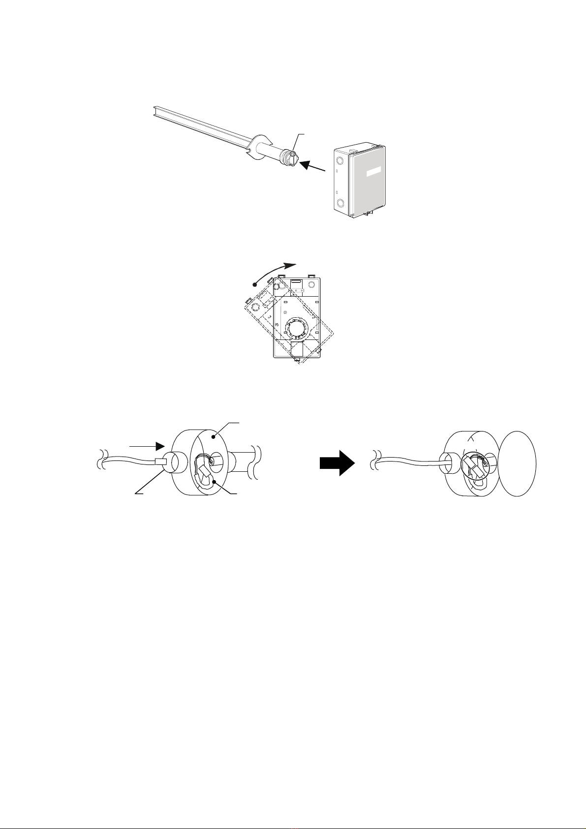
Installation and wiring must be performed by qualified personnel in accordance with all applicable safety standards.
All wiring must comply with applicable codes and ordinances.
Before wiring, be sure to turn off the power to the product.
Be sure to provide a circuit breaker for the power to the product as the product does not have a power switch.
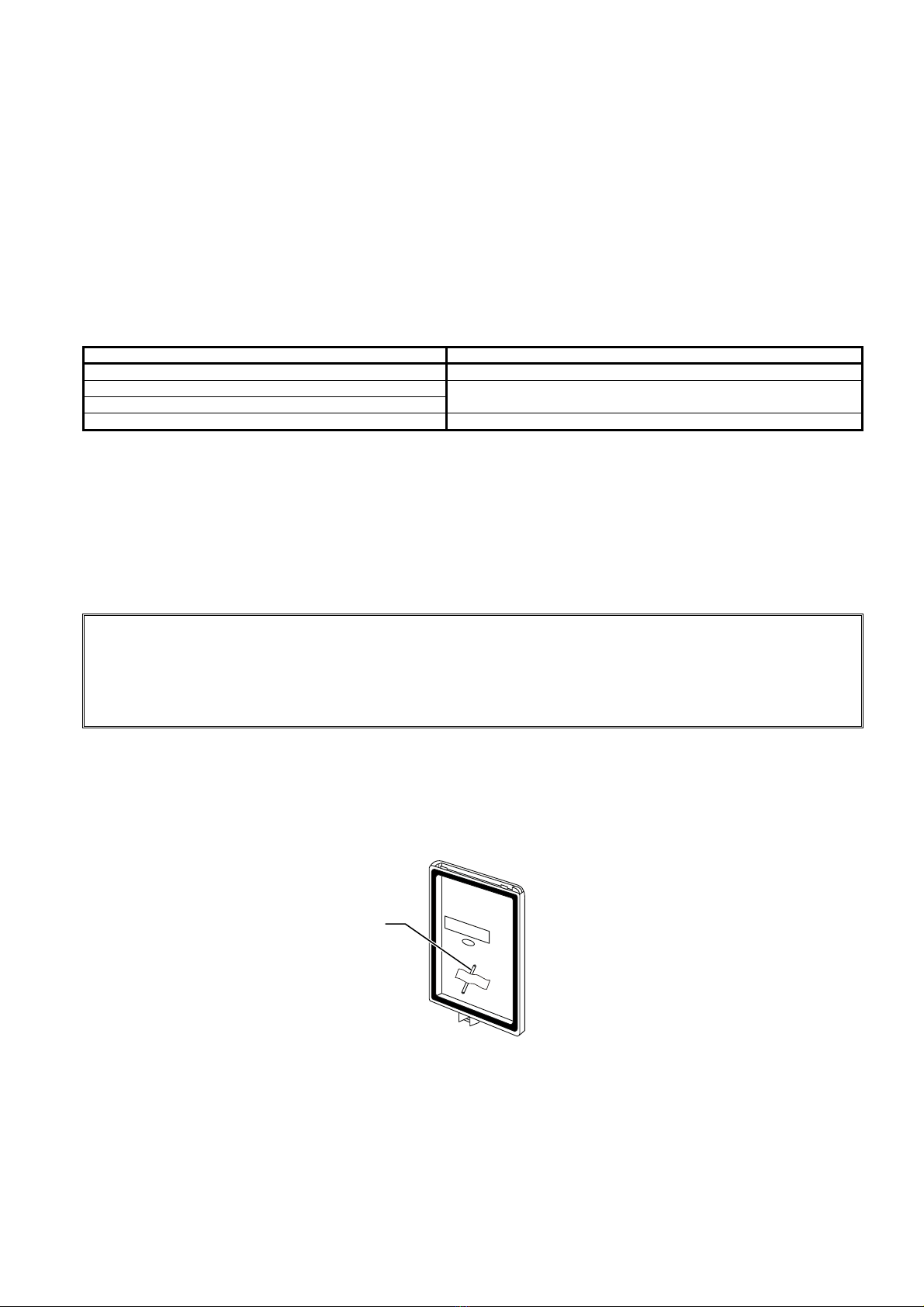
Do not disassemble the product.
Doing so might cause device failure.
Dispose of this product as industrial waste in accordance with your local regulations. Do not reuse all or a part of this
product.