Azbil HTY 7033 User manual

AB-5965
1
Ceiling Mounted Sensor
HTY7033/ TY7033
General
The HTY7033 Ceiling Mounted Sensor uses a Pt100
platinum film temperature sensing element and a poly-
mer capacitive film humidity sensing element (FP3 spe-
cially developed by Azbil Corporation) which ensures
highly accurate and reliable temperature/humidity sens-
ing. It is designed to be installed to narrow opening of
system ceilings and can be used to control or measure
temperature and humidity.
TY7033 for temperature only is also available.
Features
1) Wide sensing range.
2) Excellent long term stablility.
3) Highly resistant to environment.
4) Quick response and high repeatability.
5) Easy installation on the "double T bar" of the narrow
opening of system ceiling.
Models
HTY 7033 T 1 P 00 Humidity (1-5 V) + Temperature (Pt100) Lead wire output
TY 7033 Z 0 P 00 Temperature (Pt100) Lead wire output
TY 7033 Z 0 P 01 Temperature (Pt100) Modular jack output
Specifications/Instructions

2 AB-5965
Specifications
Item Specifications
Temp. 0 to 60 °CSensing range
Humid. 0 to 100 %RH (15 to 35 °C)
Temp. 100
Ω/0 °COutput signal
Humid. 1-5 VDC (linear to 0 to 100 %RH) (output impedance: min. 50kΩ)
Temp. +/- 0.3 °C (at 0 to 60 °C)Sensing accuracy
Humid. +/- 3 %RH (at 30 to 70 %RH 25 °C)
+/- 5 %RH (at 20 to 80 %RH 15 to 35 °C)
Temp. Max. 6 minTime constant
(at air velocity 0.15 m/s) Humid. Max. 40 seconds
Temp. Rated operating conditions: 0 to 60 °C 0 to 100 %RH (non-condensing)
Extreme operating conditions: -10 to 60 °C 0 to 100 %RH (non-condensing)
Storage conditions: -20 to 70 °C 5 to 95 %RH (non-condensing)
Environmental
conditions
Humid. Rated operating conditions: 15 to 35 °C 20 to 80 %RH (non-condensing)
Extreme operating conditions: -10 to 60 °C 0 to 100 %RH (non-condensing)
Storage conditions: -20 to 70 °C 5 to 95 %RH (non-condensing)
Power supply 24 V AC +10/-15 % (50/60 Hz), 24V DC +/- 10 % (for HTY7033)
Power consumption 0.15 VA (at 24 V AC, for only HTY7033) 100 mW (at 24 V DC, for only HTY7033)
Dielectric strength 500 V AC less than 1 mA of leak for 1 minute
Insulation resistance 500 V DC 20 MΩor more
Installation Installed in return ceiling opening
Wiring Lead wire: Length 200mm、cross section0.75 mm²
Modular jack connector (for TY7033Z0P01)
Material Case: cold-rolled steel sheet (anodized black finish)
Shield clip: SUS304
Weight Approx. 300 g
Accesorries None
Order separately None
Safety Instructions
Please read instructions carefully and use the product properly. Please keep this instruction on hand for reference at
any time.
Usage Restrictions
This product is targeted for general air conditioning. Do not use this product in a situation where human life may be
affected. If this product is used in clean rooms or places where reliability or control accuracy is particularly required,
please contact Azbil Corporation’s sales representatives. Azbil Corporation bears no responsibility for any benefit, or
lack of benefit, derived from the operation by the customer.
CAUTION
●Installer must be a trained, experienced service technician.
●Check the ratings given in this instructions to prevent equipment damage.
●Check the environment given in this instructions to prevent equipment damage.
●Disconnect power supply before wiring to prevent electric shock or equipment damage.
●All wiring must comply with local codes and ordinances.
●Do not remove or disassemble casing except for wiring. May result in equipment damage.
●When the product is faulty, the reduced output may result in excessively humid status. Take safety
measures at controller.

3 AB-5965
Dimensions(mm)
Installation
Cautions on installation
Place spacers between the parallel T bars as shown be-
low to minimize vibration.
Installation of spacer for double T bar
Mounting
Mount the sensor between the parallel T bars. Hold the
springs and push into opening, then release springs.
Installation procedure
Wiring
Wiring and color of lead wire
Applicable products (confirmed)
Maker Aluminum Steel
Matsushita Electronics ○○
Daiken AT25
AT25256
○
Nittou Bouseki 4025 ---
Okuju I, D-1 ---
“Double T bar” is not standardized.
Confirm the type of double T bar to be in-
stalled to.
approx. 85
95
7535
50 to 53
“Double T bar”
Sensor SpacerSpacer
100 +/- 5 mm T bar
~(+)
Pt100
Brown
Black
Blue
Black
Red
White
White
A
B
B
24V AC
(24V
1-5VDC
Black wire of power supply and humidity output is
wired inside sensor.
J1
<
<
<
<
<
<
<
<
1 (A)
2 (B)
3 (A)
4 (B)
5 NC
6 (B)
7 NC
8
(
B
)
TY7033Z0P01
HTY7033T1P00
Power
supply
⊥
(–)
+
–
TY7033Z0P00
Pt100
Humidity
Temp-e
rature

4 AB-5965
Cautions on wiring
Use shielded multi conductor cable (CVV-S) of 1.25 mm²
for humidity output. IV cable of min. 1.25 mm² may also
be used. Be sure to ground the shielded cable at the
controller side.
Maximum wiring length is 100 m.
Do not connect power supply to temperature output.
Always check the wiring before power is supplied.
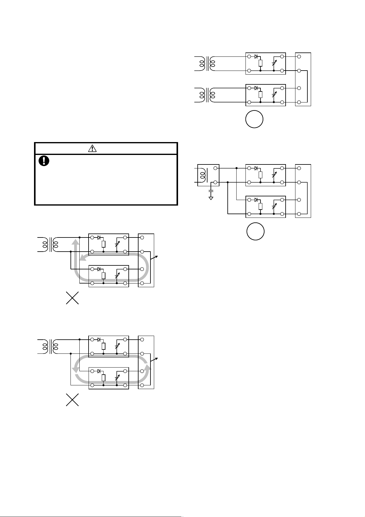
Never share 24V AC transformer with other equipment.
Connect Separate Fransformers
CAUTION
Use insulated transformer to supply 24V AC
power supply voltage.
Never share 24V AC power supply with other
equipment.
If a transformer is shared with other equipment,
loop will be formed at common and the sensor
may be damaged.
•Transformer (24V AC power supply) shared
•Separate transformer (24V AC power supply)
•24V DC power supply shared
Follow the next instructions to prevent an induction cur-
rent flowing from the humidity sensor to the controller
input circuit, or to prevent an influence on the generating
noise due to inadequate time constant of the controller
input.
•Use a controller with a low pass filter with a removal
ratio of 40dB or higher (normal mode).
•Connect an isolator to the controller input circuit if a
removal ratio is unknown.
•If you use a Azbil Corporation cotnroller, no problem
will occur.
Maintenance
Since the temperature/humidity sensor have been in-
spected and adjusted accurately before shipment, they
need no adjustment at the site. However, follow the
maintenance instructions below :
1) Periodical inspection
Determine the periodical inspection intervals according
to the amount of suspended dust and other
contaminants in the environment. Regulary check the
sensor’s accuracy and the condition of its cover.
2) Troubleshooting
If any problem occurs during operation, refer to the
following table for appropriate solutions.
Common loop formed
Not Good
24V
A
C
+
⊥
+
-
+
-
+~
⊥
~
-
-
Humidity/temperature
senso
r
Humidity/temperature
senso
r
Multi-loop
controlle
r
Common
share
The transmitter will be
shorted if miss-wired.
Not Good
24VAC
Multi-loop
controlle
r
Common
share
+
⊥
+
-
+
-
+~
⊥
Temperature/humidity
senso
r
~
-
-
Temperature/humidity
senso
r
No common loop formed
Good
Common loop formed, however, not
so affected by common mode noise.
Good
24VAC
+
-
+
-
~
⊥
24VAC
~
⊥
+
-
+
-
Multi-loop
controlle
r
Temperature/humidity sensor
24VDC
⊥
+
-
+
-
~
⊥
~
+
-
+
+
-
-
Multi-loop
controlle
r
Temperature/humidity sensor

5 AB-5965
Troubleshooting
Problem… Check… Action…
- No output
generated
- Unstable output
- Check loose
connection
- Check Incorrect
wiring
- Check supply
voltage
- Check sensor
damage
- Re-connect the wire
- Replace sensor
- Slow response
- Error in output
- Check the sensor
for water leakage or
condensation
- Check the installed
location
- Check the dust.
soil.
- Remove cover
Dry the unit with no
power.
- Refer to the
Installation
instructions
- Clean the cover
- Replace the sensor
- Humifity one point
adjustment
3) Humidity one point adjustment
When you find a calibration error in the humidity
sensor, re-calibrate the sensor using the adjustment
volume (VR1, VR2) located on the circuit board. The
output value is increased by turning this volume in
clockwise direction and decreased by turning it
counterclockwise. Use refelenced humidity meter of
adequate accuracy. A digital multimeter is
recommended to check the output voltage.
Parts Identification of Adjustment volume
Cautions
1. After unpacking, age the transmitter in the ambient
atmosphere for at last 24 hours.
2. To calibrate and adjust, take care the heat from
human body or appliances.
Fine adjustment volume (VR1)
Temperature element
Humidit
y
element
Rough adjustment volume (VR2)

Specifications are subject to change without notice.
Building Systems Company
http://www.azbil.com/
Rev.1.1 Jul. 2012 AB-5965 0.5H-H (W)
Printed in Japan.
This manual suits for next models
1
Table of contents
Other Azbil Accessories manuals

Azbil
Azbil SES70 User manual

Azbil
Azbil SES70 User manual

Azbil
Azbil AUD100 Series User manual

Azbil
Azbil HTY7843 User manual

Azbil
Azbil HTY78 User manual

Azbil
Azbil TY7043D User manual

Azbil
Azbil HP7 Series User manual

Azbil
Azbil AUD100 Series User manual

Azbil
Azbil K1G Series User manual

Azbil
Azbil CY8100C1001 User manual