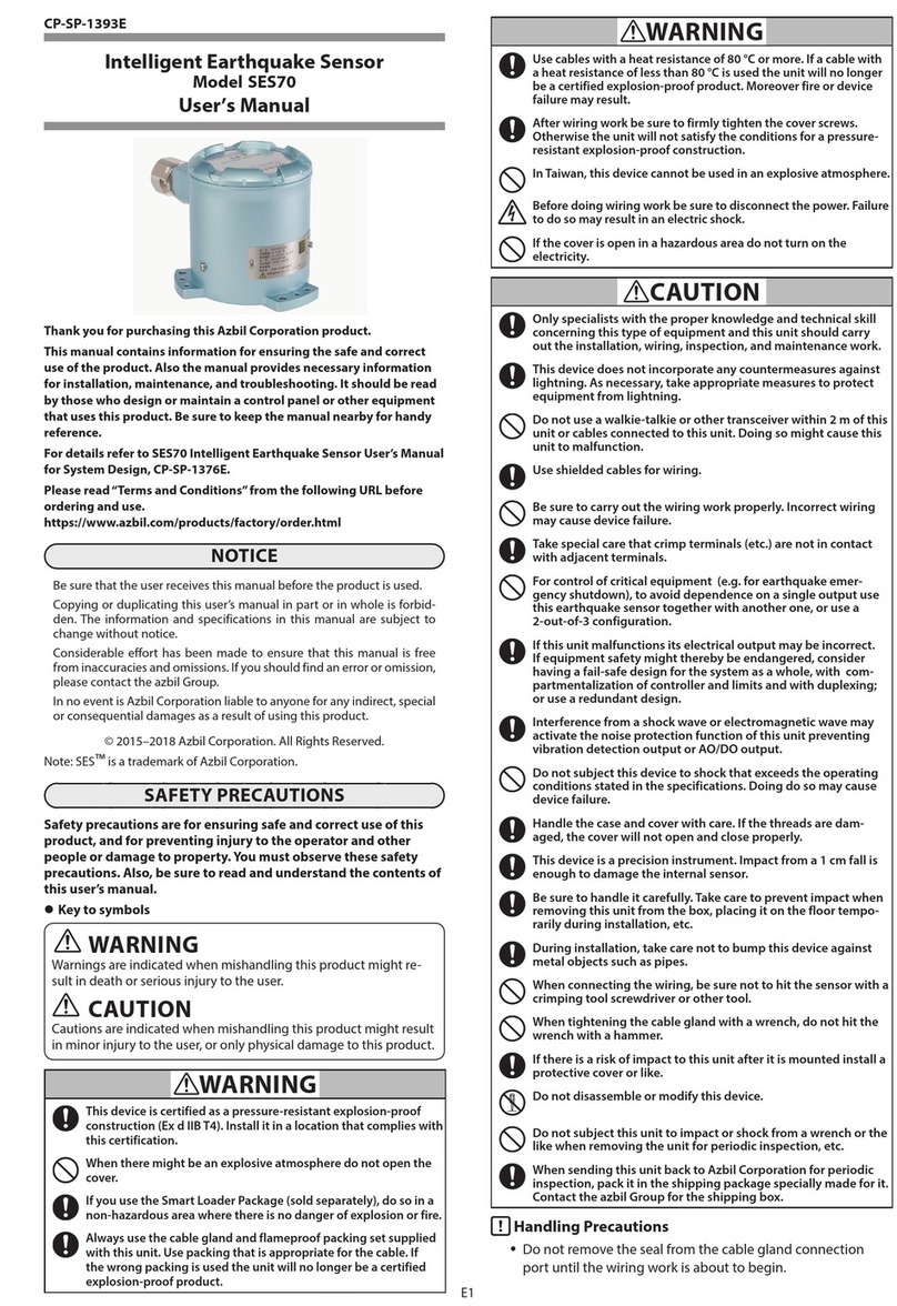
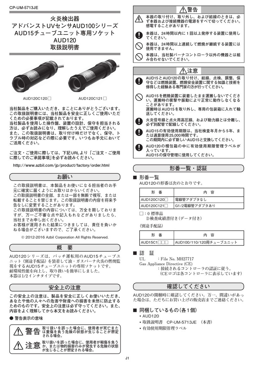
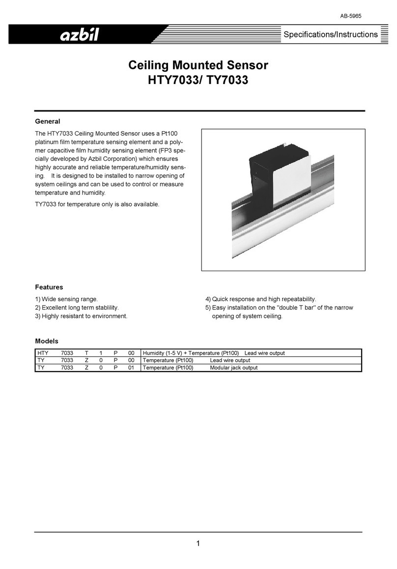
Azbil SES70 User manual

Thank you for purchasing an Azbil
Corporation product.
This manual contains information for
ensuring the correct use of this product.
It also provides necessary information
for installation, maintenance, and
troubleshooting.
This manual should be read by those who
design and maintain equipment that uses
this product. Be sure to keep this manual
nearby for handy reference.
Intelligent Earthquake
Sensor
Model SES70
User’s Manual
for
System Design
No. CP-SP-1376E

NOTICE
Be sure that the user receives this manual before the product is used.
Copying or duplicating this user’s manual in part or in whole is forbidden.
The information and specifications in this manual are subject to change
without notice.
Considerable effort has been made to ensure that this manual is free from
inaccuracies and omissions. If you should find an error or omission, please
contact the azbil Group.
In no event is Azbil Corporation liable to anyone for any indirect, special or
consequential damages as a result of using this product.
© 2015–2018 Azbil Corporation. All Rights Reserved.
SES™is a trademark of Azbil Corporation in Japan.

i
Conventions Used in This Manual
The safety precautions explained in the following section aim to prevent injury to the operator and
others, and to prevent property damage.
WARNING
Warnings are indicated when mishandling this product might
result in death or serious injury.
CAUTION
Cautions are indicated when mishandling this product might
result in minor injury to the user, or physical damage to the
product.
In describing the product, this manual uses the icons and conventions listed below.
Use caution when handling the product.
The indicated action is prohibited.
Always follow the indicated instructions.
Handling Precautions:
Handling Precautions indicate items that the user should pay attention to when handling
this product.
Note: Notes indicate information that might benefit the user.
(1), (2), (3): Numbers within parentheses indicate steps in a sequence or parts of an explanation.
This indicates the item or page that the user is requested to refer to.
Label and seal
The following nameplate, label, and seal are attached to this unit.
Rating nameplate Warning label Seal

ii
Safety Precautions
Safety precautions are intended to ensure the safe and correct use of this product, to prevent injury to the operator
and others, and to prevent damage to property. Be sure to observe these safety precautions. Please make sure you un-
derstand the safety guidelines before reading the rest of this manual.
The use of this product in a manner not specified by the manufacturer will impair its built-in safety features.
WARNING
For explosion-proof instrumentation, install and wire this unit in accordance with the National
Institute of Industrial Safety's "User's Guidelines for Electrical Installations for Explosive Gas
Atmospheres in General Industry" (Tokyo, 1994 [in Japanese]).
This device is certified as a pressure-resistant explosion-proof construction (Ex d IIC T4). Install
it in a location that complies with this certification.
In Taiwan, this device cannot be used in an explosive atmosphere.
If there might be an explosive atmosphere, do not open the cover. Doing so may cause
explosion or fire.
If you use the Smart Loader Package (sold separately), do so in a non-hazardous area where
there is no danger of explosion or fire.
Always use the cable gland and flameproof packing set supplied with this unit. In addition,
use packing that is appropriate for the cable. If the wrong packing is used, the unit will no
longer be a certified explosion-proof product.
Use cables with a heat resistance to temperatures of 80 °C or more. If a cable with a heat
resistance of less than 80 °C used, the unit will no longer be a certified explosion-proof
product. Moreover, fire or device failure may result.
After wiring work, be sure to firmly tighten the cover screws. Otherwise the unit will not satisfy
the conditions for a pressure-resistant explosion-proof construction.
Before doing wiring work, be sure to disconnect the power. Failure to do so may result in an
electric shock.
If the cover is open in a hazardous area, do not turn on the electricity. Doing so may cause
explosion or fire.
CAUTION
Only specialists with the proper knowledge and technical skill concerning this type of
equipment and this unit should carry out the installation, wiring, inspection, and maintenance
work.
This device does not incorporate any countermeasures against lightning. As necessary, take
appropriate measures to protect equipment from lightning.
Do not use a walkie-talkie or other transceiver within 2 m of this unit or cables connected to
this unit. Doing so may cause this unit to malfunction.
Use shielded cables for wiring.
iii
CAUTION
Be sure to carry out the wiring work properly. Incorrect wiring may cause device failure.
Do not allow crimp terminals (etc.) to come into contact with adjacent terminals. Doing so may
cause fire or device failure.
For control of critical equipment (e.g., for earthquake emergency shutdown), to avoid
dependence on a single output, use this earthquake sensor together with another one, or use
a 2-out-of-3 configuration.
If this unit malfunctions, its electrical output may be incorrect. If equipment safety might
thereby be endangered, consider having a fail-safe design for the system as a whole, with
compartmentalization of controller and limits and with duplexing or use a redundant design.
Interference from a shock wave or electromagnetic wave may activate the noise protection
function of this unit, preventing vibration detection output or AO/DO output.
Handle the case and cover with care. If the threads are damaged, the cover will not open and
close properly.
Do not subject this device to shock that exceeds the operating conditions stated in the
specifications. Doing do so may cause device failure.
This device is a precision instrument. Impact from a 1 cm fall is enough to damage the internal
sensor.
Be sure to handle it carefully. Take care to prevent impact when removing this unit from the
box, placing it on the floor temporarily during installation, etc.
During installation, take care not to bump this device against metal objects such as pipes at
the work site.
When connecting the wiring, be sure not to hit the sensor with a crimping tool, screwdriver, or
other tool.
When tightening the cable gland with a wrench, do not hit the wrench with a hammer.
If there is a risk of impact to this unit after it is mounted, install a protective cover or like.
Do not disassemble or modify this device.
Do not subject this unit to impact or shock from a wrench or the like when removing the unit
for periodic inspection, etc.
When sending this unit back to Azbil Corporation for periodic inspection, pack it in the
shipping package specially made for it. Contact the azbil Group for the shipping box.
Handling Precautions
• Do not remove the seal from the cable gland connection port until the wiring
work is about to begin.

iv
This unit withstands an impact of 490 m/s
2
(50 G). Because this device is a precision instrument, handle
it with care. Two metal objects knocking together can create an impact of several tens of thousands of
m/s
2
(several thousands of Gs).
Prohibited actions
(1) Dropping the unit on the floor (2) Casually putting the unit down on a table or
stand (put it down gently)
(3) Bumping the unit against pipes, etc. (4) Striking the unit with a tool
(5) Hitting a tool (during installation or wiring) (6) Hitting the tool (to open the cover)

v
The Role of This Manual
There are four different manuals related to the SES70. Read them as necessary for your specific requirements. If a
manual you require is not available, contact the azbil Group or its dealer.
Intelligent Earthquake Sensor Model SES70 User’s Manual for System Design
Manual No. CP-SP-1376E
This manual.
First-time users of the SES70 and those designing or maintaining hardware that uses the
SES70 should read this manual thoroughly. This manual gives an overview and hardware
specifications, and describes installation, wiring, setup, operation, and troubleshooting.
Intelligent Earthquake Sensor Model SES70 User's Manual
Manual No. CP-SP-1393E
This manual is supplied with the SES70. Personnel in charge of the installation or
wiring of this device, or in charge of the design or maintenance of hardware that
uses this device, should read this manual thoroughly. The manual gives an over-
view of this device and describes installation methods, wiring, startup preparation,
and troubleshooting.
SLP-SE7 Smart Loader Package for SES70 Intelligent Earthquake Sensor
Manual No. CP-SP-1394E
This manual is included on the SLP-SE7 installation disk. After installation, person-
nel in charge of settings or in charge of monitoring the device's operation should
read this manual thoroughly. The SLP-SE7 is used for monitoring and configuration
of the SES70 on a PC. The manual describes installation on a PC, loader functions,
and loader operation.

vi
Organization of This User's Manual
This manual is organized as follows.
Chapter 1. OVERVIEW
Features and models
Chapter 2. NAMES AND FUNCTIONS OF PARTS
Names and functions of parts
Chapter 3. INSTALLATION
Installation methods, important notes, and locations
Chapter 4. WIRING
Wiring procedures, connection examples, and precautions for wiring
Chapter 5. PREPARATIONS FOR START-UP
What to check before use and how to set the time
Chapter 6. INTERNAL PROCESSING
Basic operation modes, calculations, control output, waveform recording, and error
diagnosis
Chapter 7. LOADER ACCESS DATA
Data accessed by the SLP-SE7 from a PC (For details on the loader, see
SLP-SE7 Smart Loader Package for SES70 Intelligent Earthquake Sensor, No.
CP-UM-5756E.)
Chapter 8. MAINTENANCE AND TROUBLESHOOTING
Troubleshooting and Countermeasures
Chapter 9. DISPOSAL
Disposal
Chapter 10. SPECIFICATIONS
General specifications, performance specifications, and external dimensions
APPENDIX
Glossary and method of determining acceleration accuracy

vii
Contents
Conventions Used in This Manual
Safety Precautions
The Role of This Manual
Organization of This User's Manual
Chapter 1. OVERVIEW 1-1
Application 1-1
Features 1-2
Model selection 1-3
Chapter 2. NAMES AND FUNCTIONS OF PARTS 2-1
Names of parts 2-1
Basic function block diagram 2-1
Internal structure 2-2
Measurement principles 2-2
Chapter 3. INSTALLATION 3-1
Installation Location 3-1
Installation Instructions 3-1
Chapter 4. WIRING 4-1
Wiring Procedure 4-2
Connecting the battery 4-6
Lightning surge protection 4-6
Chapter 5. PREPARATIONS FOR START-UP 5-1
Procedure for setting the clock 5-1
Chapter 6. INTERNAL PROCESSING 6-1
6-1 Modes 6-1
Mode transition 6-1
Functions of the modes 6-2
6-2 Internal Calculation Processes 6-7
Internal Calculation 6-7
Various calculations and judgment processes 6-8
SI calculation 6-10
Synthesized AC acceleration calculation 6-11

viii
Calculation of the JMA seismic intensity scale equivalent value 6-12
Relationship of the JMA scale (shindo scale), acceleration, SI value, and mea-
sured seismic intensity (shindo) 6-12
Noise protection process 6-12
6-3 Waveform Recording 6-13
Waveform recording header information 6-13
Automatic waveform recording 6-13
Example of maximum value recording without trigger update 6-15
Example of maximum value recording with trigger update 6-17
Example of threshold value recording 6-19
Forced waveform recording 6-21
Example of waveform recording 6-21
6-4 Vibration Detection and Liquefaction Judgment Functions 6-22
Vibration detection judgment function 6-22
Liquefaction judgment function 6-22
6-5 Noise Protection Function 6-24
6-6 Error Diagnosis Functions 6-26
Failure level standards 6-26
Diagnostic functions according to the mode 6-27
Various error diagnosis functions 6-27
6-7 Output Functions 6-29
Output update and hold processes 6-29
Hold process 6-29
Manual output 6-30
Output adjustment (constant drift) 6-31
Output adjustment (high-frequency noise) 6-31
Output selection 6-32
Outputs according to mode 6-33
6-8 Maintenance Sequence 6-34
Maintenance sequence 6-34
6-9 LED Output Functions 6-36
Chapter 7. LOADER ACCESS DATA 7-1
Real-time data monitoring data 7-1
Changing of settings 7-2
Waveform recording 7-6
Manual output function 7-6
Diagnosis and adjustment function 7-8
Chapter 8. MAINTENANCE AND TROUBLESHOOTING 8-1
Checklist for periodic inspection 8-1
How to replace the battery 8-1
Troubleshooting 8-2

ix
Chapter 9. DISPOSAL 9-1
Chapter 10. SPECIFICATIONS 10-1
10-1 Specifications 10-1
10-2 Performance Specifications 10-3
10-3 Other Specifications 10-4
Communication specifications 10-4
External dimensions 10-4
APPENDIX App-1
Glossary App-1
Method of determining acceleration accuracy App-2
Relationships between JMA seismic intensity, acceleration, SI value, and mea-
sured JMA seismic intensity App-5


1-1
Chapter 1. OVERVIEW
Application
The SES70 Intelligent Earthquake Sensor calculates seismic intensity (SI), which
represents estimated structural damage, and the Japan Meteorological Agency
(JMA) seismic intensity scale (shindo scale) equivalent value, based on acceleration
signals generated from the built-in accelerometer.
Additionally, the unit judges ground liquefaction from the acceleration waveform
characteristics, and outputs the results.
zApplication examples
1. Earthquake emergency shutdown and remote monitoring system
SI value/acceleration, etc.
DCX350 (Azbil Corporation’s
remote data collector)
Shuto valve
To communications line
Vibration detection output
SES70
2. Earthquake monitoring system
RS-485
SES70
Display unit (with application software)
Lamp, etc.
3. Earthquake monitoring with 2-out-of-3 shutdown system
RS-485
SES70
Display unit (with application software)
SES70 SES70
Shuto valve
Vibration detection output
2-out-of-3 relay circuit
To create a redundant system, take into account the following:
• If electrical noise is expected, keep wiring away from sources of noise.
• If interference from other vibration or shock is expected, install the SES on a foun-
dation separated as far as possible from the source of the vibration or shock.

Chapter 1. OVERVIEW
1-2
Features
The SES70 calculates seismic intensity (SI), which represents estimated structural
damage, and the JMA seismic intensity scale equivalent value, based on accelera-
tion signals generated from the built-in accelerometer, and it can output the results.
Additionally, the unit can judge ground liquefaction from the acceleration wave-
form characteristics, and can output the results.
Other features are shown below:
• Thanks to the 3 axes (north-south, east-west, and up-down = X, Y, Z) of the
servo accelerometer, high-accuracy acceleration measurement is possible by
characterization of the acceleration waveforms.
• Two independent acceleration values are available for different purposes, either
calculation or control. A filter coefficient and the number of axes for synthesized
AC acceleration can be set individually for acceleration values.
• The unit synthesizes acceleration signals as vectors and, based upon the maxi-
mum value within the time window, it calculates the synthesized AC acceleration
for calculation and the synthesized AC acceleration for control. The synthesized
AC acceleration selected for the PV can be output as a 4–20 mA analog signal.
• By vector projection of the AC acceleration for calculation signals in 8 directions
in a horizontal plane, the unit executes a speed response calculation in 8 direc-
tions in real time. The maximum value obtained within the time window is out-
put as the SI value. The SI value can be output as a 4–20 mA analog signal.
• Regarding SI calculation, in addition to speed response calculation in 8 direc-
tions (7 natural periods), calculation in 16 directions (24 natural periods) can be
chosen. The selected SI values are used for the PV, vibration detection judgment,
waveform recording, analog output (AO), etc.
• The JMA shindo earthquake scale is calculated with an approximate formula that
uses the SI value and the synthesized AC acceleration for calculation. The result-
ing JMA seismic intensity scale equivalent value can be output as a 4–20 mA
analog signal.
• The liquefaction detection algorithm, which uses a horizontal 2-axis calculation
AC, detects the occurrence of liquefaction. When it is detected, the liquefaction
detection output turns ON.
• The automatic waveform recording function can record ten 360-second wave-
forms of 3-axis acceleration signals at a 10 ms sampling cycle when triggered by
the synthesized AC acceleration value for calculation, the SI value, or the JMA
seismic intensity scale equivalent value for the measured vibration waveforms.
The recorded waveform signals can also be read on a PC using the loader.
• The automatic waveform recording function can operate on the basis of maxi-
mum value recording with trigger update, maximum value recording without
trigger update, or threshold value recording.
• The forced waveform recording function can record one waveform for 360 s
using the loader.
• Waveform files record the following header information: trigger time, SI value of
the recorded waves, synthesized AC acceleration value for calculation, JMA seis-
mic intensity scale equivalent value, maximum Sv value of the 7 selected natural
periods in the waveform records, and checksum value for the waveform data.
This information can be read out via communications.

Chapter 1. OVERVIEW
1-3
• The vibration detection contact output signals turn ON according to the results
of calculation and according to the following four conditions with AND or OR
relationships:
• When the SI value exceeds the preset value
• When the JMA seismic intensity scale equivalent value exceeds the preset
value
• When the synthesized AC acceleration value (for calculation or for control)
selected for the PV exceeds the preset value
• When liquefaction is detected There are three vibration detection contact out-
puts, for which individual conditions can be set.
• The user can adjust the 4–20 mA analog output using the PV bias and PV low
cutoff function.
• During operation, various diagnostics are conducted. If an error is found, a
minor or serious failure will occur. The diagnosis results are output to the minor
failure or serious failure output.
• If there is a large acceleration input that does not have seismic wave character-
istics, the noise (interference) protection function of this unit will be activated.
When activated, noise protection affects the vibration detection output and ana-
log output for about 1 minute. During this time the noise protection output is
ON.
• If the unit receives a digital input signal, it goes into maintenance mode, sus-
pends the basic earthquake measurement functions, and executes DO, AO, and
relay output sequence operations for accelerometer and input/output diagnosis.
In the case of abnormal results from the accelerometer diagnosis, a serious fail-
ure occurs.
• The following operations can be done with the loader: changing various calcula-
tion parameters such as vibration detection output settings, collecting waveform
records, monitoring the measured values, and monitoring detailed error diagno-
sis results.
• Data can be read and settings can be changed remotely through RS-485 commu-
nications.
A DCX350 remote data collector and a dedicated display unit (with application
software) can be connected.
• Using the loader, the settings can be changed to obtain functions (input/out-
put and operation) that are basically equivalent to those of the SES60 (the old
model).
• The unit casing has a pressure-resistant explosion-proof construction (Ex d IIC
T4) and an IP67 seal.
Model selection
Standard model SES70AV320-1110
With inspection report SES70AV320-111D
Inspection report + traceability certicate SES70AV320-111Y


2-1
Chapter 2.
NAMES AND FUNCTIONS OF PARTS
Names of parts
Flameproof
packing
Flameproof
packing set
Washer
Rating nameplate
O-ring
External ground terminal
Warning label
Reference plane
Cable gland
Cover
Case
Cable clamp
Lock nut
Washer
ZX
Y
Loader jack socket
Battery connector (2 places)
Battery
Battery holder
Status display LEDs
LEDs 1 to 3: red
LED 4: green
Spring terminal
block (10 terminals)
Internal ground terminal
φ7 device mounting hole (3 places)
Level adjustment M6
screw hole (3 places)
Adjustment hole for manufacturer
use only (3 places)
Screw terminal block
(M3.5, 8 terminals)
(For cable connections, use ring
crimp terminals suitable for
cables whose cross-sectional
area is 4 mm2or larger.)
Acceleration measurement axes
Along the Z axis, the direction of
the earth's gravitation is the
positive direction.
Note
• The arrows for the acceleration measurement axes show the directions of
acceleration in response to vibration. When the sensor moves in the direction
indicated by an arrow, the acceleration is positive in that direction. When
the sensor is tilted in the direction indicated by an arrow, the acceleration is
measured as negative in that direction.
Measurement principles (P. 2-2)
Basic function block diagram
Temperature
sensor
Accelerometer
Input signal processing
16-bit A/D
conversion circuit
D/A conversion
circuit
Accelerometer
self-diagnosis
Calculation and
input/output judgment
CPU
Memory
Waveform records
Clock
Input-output
control circuit
Vibration detection relay output (3)
Synthesized AC
acceleration output (AO1)
SI value output (AO2)
Minor failure output (DO1)
Serious failure output (DO2)
Noise protection output (DO3)
Liquefaction detection output (DO4)
RS-485 (DA)
RS-485 (DB)
Mode transition request input (DI)
Smart Loader communication
X
Y
Z
Changeable
Note: The memory and the clock are backed up by the battery.

Chapter 2. NAMES AND FUNCTIONS OF PARTS
2-2
Internal structure
111 mm
122.5 mm
RISC microcomputer
real-time SI calculation
Explosion-proof case
Waveform records
Accelerometer
Measurement principles
The accelerometer uses a highly sensitive position detector to precisely detect the
positional deviation of the pendulum in response to acceleration. It then sends an
electrical signal (current) proportional to the positional deviation of the pendulum
from the servo-amplifier to the drive circuit (drive coil+magnet) in order to return
the pendulum to the reference point position.
Since the electrical signal from the servo-amplifier is proportional to the accelera-
tion, the acceleration can be measured from the electrical signals.
In the accelerometer, the pendulum is normally located at the reference position
when in the earthquake measurement state, and stress applied to the spring of the
pendulum does not affect the measurement. Therefore, acceleration can be mea-
sured with high accuracy.
P: Pendulum
B: Spring
C: Drive coil
M: Magnet
D: Position detector
S: Servo circuit
I: Electrical signal for measurement
B
P
I
S
D
MC
Structure of the accelerometer
Handling Precautions
• If the unit is dropped accidentally or if a falling object, etc., strikes the unit,
device failure may result. Take care when installing the unit.

3-1
Chapter 3. INSTALLATION
WARNING
For explosion-proof instrumentation, install and wire this unit in accordance with the National
Institute of Industrial Safety's User's Guidelines for Electrical Installations for Explosive Gas
Atmospheres in General Industry (Tokyo, 1994 [in Japanese]).
This unit is certified as a pressure-resistant explosion-proof construction (Ex d IIC T4).
Install this unit in a location conforming to the conditions for a flameproof structure.
In Taiwan, this device cannot be used in an explosive atmosphere.
CAUTION
During installation or maintenance work, take care not to drop the unit accidentally to prevent
injury to feet, etc.
This unit is not protected against lightning. As necessary, take appropriate instrumentation to pro-
tect equipment from lightning.
Do not subject this device to shock that exceeds the operating conditions stated in the specifica-
tions. Doing do so may cause device failure.
Installation Location
Avoid installing the device where it will be subject to conditions such as the following.
• Ambient temperature below −10 °C or above +60 °C
• Humidity higher than 90 % RH
• Sudden temperature fluctuations causing condensation
• Corrosive or combustible gas.
• Large amounts of conductive substances (e.g., dust, salt, or iron powder) or
organic solvents
• Direct shock or vibration other than earthquake motion
• Direct sunlight
• Large amounts of water or rain
• Splashing by fluids (e.g., oil or chemicals)
• Strong magnetic or electrical fields
Installation Instructions
This unit measures ground acceleration caused by earthquake motion in order to
calculate the estimated amount of damage. Installation of this unit on a concrete
foundation separated from buildings is recommended so that building vibration
does not affect measurement.
In addition, where needed to prevent direct exposure to sunlight or rain, provide a
protective roof or cover.
Handling Precautions
• Do not use the three adjustment holes (which are for manufacturer use only)
when installing the unit.
• When installing the unit on a concrete foundation, check that the foundation
is not hollow by tapping it with a small hammer.

Chapter 3. INSTALLATION
3-2
When installing this unit, select one of the methods shown below, depending on the
installation conditions.
zIf the installation surface is level within ±3°
(1) Select a flat concrete surface for installation.
(2) Put three anchors in the surface, aligned with the three 7 mm mounting holes in
the unit.
(3) Attach the unit with the three mounting screws (M5 × 30 mm).
Sensor unit
Concrete
Anchor
Note
• Example of an anchor: PY4002 AY plug bolt
zIf the installation surface is not level
(1) Get a metal plate (10 mm thick or more) with three holes for level adjustment
and three threaded M5 holes for attaching the unit. The dimensions of the
mounting plate are shown below.
Unit: mm
104
103
43
44.5
82
17
41
123
15
71
142
10
φ13 (3 places)
M5 (3 places)
Handling Precautions
• If the mounting plate is attached to a concrete surface, use M10 or larger
anchors.
The diameter of the corresponding holes in the plate is 13 mm.
Other manuals for SES70
1
Table of contents
Other Azbil Accessories manuals

Azbil
Azbil TY7043D User manual

Azbil
Azbil HTY78 User manual

Azbil
Azbil HTY7843 User manual

Azbil
Azbil K1G Series User manual

Azbil
Azbil HP7 Series User manual

Azbil
Azbil AUD100 Series User manual

Azbil
Azbil K1G Series User manual

Azbil
Azbil SES70 User manual

Azbil
Azbil HTY 7033 User manual

Azbil
Azbil AUD100 Series User manual