Azbil AUD100 Series User manual

J1
CP-UM-5640JE
チューブユニット(形AUD15)専用ソケット
形AUD100/110
取扱説明書
形AUD100 形AUD110
このたびは本製品をご購入いただき、まことにありがとうご
ざいます。この取扱説明書には、製品を安全に正しくご使用
いただくための必要事項が記載されております。本製品を使
用した装置の設計、保守を担当される方は、必ずお読みになり、
理解したうえでご使用ください。いつもお手元においてご活
用ください。
ご注文・ご使用に際しては、下記URLより「ご注文・ご使用
に際してのご承諾事項」を必ずお読みください。
https://www.azbil.com/jp/product/factory/order.html
お願い
この取扱説明書は、本製品をお使いになる担当者のお手元に
確実に届くようにお取りはからいください。
この取扱説明書の全部、または一部を無断で複写、または転
載することを禁じます。この取扱説明書の内容を将来予告な
しに変更することがあります。
この取扱説明書の内容については、万全を期しておりますが、
万一ご不審な点や記入もれなどがありましたら、当社までご
連絡ください。
お客さまが運用された結果につきましては、責任を負いかね
る場合がございますので、ご了承ください。
安全上の注意
この安全上の注意は、製品を安全に正しくお使いいただき、
あなたや他の人々への危害や財産への損害を未然に防止する
ためのものです。安全上の注意は必ず守ってください。また、
内容をよく理解してから本文をお読みください。
● シンボル表示の意味
警告 取り扱いを誤った場合に、使用者が死亡または重傷
を負う危険の状態が生じることが想定される場合。
注意 取り扱いを誤った場合に、使用者が軽傷を負うか、
または物的損害のみが発生する危険の状態が生じ
ることが想定される場合。
警告
本器の取り付け、取り外し、および結線のときは、
本器および接続機器の電源をすべて切ってください。
感電することがあります。
本器は、24時間以内に1回以上発停する装置に使用
してください。
本器は、24時間以上連続して燃焼が継続する装置に
は使用できません。
本器は、当社製バーナコントローラ以外の機器とは
組み合わせないでください。
注意
AUD15 とAUD100/110の取り付け、結線、点検、
調整、保守などは燃焼装置、燃焼安全装置に関する
知識と技術を修得した経験ある専門家の方が行って
ください。
AUD15を燃焼装置に装着したまま運搬しないでくだ
さい。運搬時の衝撃や振動により正常に動作しなく
なることがあります。
運搬時はAUD15を取り外し、専用の包装箱に入れて
輸送してください。
火炎信号線と点火用高圧線、および動力線とは分離
し、別配管で配線してください。
有効使用期限は、通算使用時間で25,000時間または
当社検査年月から5年間です。どちらか早い期間で新
しいUVセンサと交換してください。
注 通算使用時間とは、UVセンサが火炎検出してい
る時間です。
AUD100/110の梱包箱の中に有効使用期限管理ラベ
ルが入っています。AUD15の保守管理に使用してく
ださい。
概 要
AUD100 は、バッチ運転用の AUD15 チューブユニットを装着
して油・ガスバーナ火炎の燃焼監視をする専用ソケットです。
リード線タイプ AUD100 と端子台タイプ AUD110 の 2 種類か
ら配線や設置状況に応じて選択ができます。
形番一覧・認証
■ 形番一覧
AUD100/110の形番は次のとおりです。
形 番 内 容
AUD100C100□ アドバンストUVセンサ リード線タイプ、
AUD15別売
AUD100C1000−A15 アドバンストUVセンサ リード線タイプ、
AUD15同梱
AUD110C100□ アドバンストUVセンサ 端子台タイプ、
AUD15別売
AUD110C1000−A15 アドバンストUVセンサ 端子台タイプ、
AUD15同梱
□:0 標準品
D検査成績書付き(データ付き)
T熱帯処理(AUD110Cだけ)
B検査成績書付き+熱帯処理(AUD110Cだけ)
■ 認 証
認 証 指 令 File No. 他 備 考
UL ー MH27717 ー
CE
GAR (EU)2016/426
ー
組み合わせるバーナコ
ントローラの取扱説明
書またはCE 宣言書を
ご覧ください
RoHS(2011/65/EU)
ー ー
確認してください
お買い上げいただいた形 AUD100/110は、次のものが同梱さ
れています。
• 形 AUD100/110
• 形 AUD15(選択した形番による)
• 取扱説明書(本書) CP-UM-5640JE
• 有効使用期限管理ラベル

J2
■ ラベル
●有効使用期限管理ラベル
本器の梱包箱の中に入っています。
AUD15 の保守管理に使用してください。
取扱説明書をよく読み、正しくお使いください。
有効使用期限管理ラベル
バーナNo.
有効使用期限形 番/名 称
Effective operation time label
Effective operation time
Model/NameBurner No.
before using and use it correctly.
Please read instructions carefully
9735-001-02
取り扱い上の注意
• 有効使用期限欄には、バーナ稼働時間から計算した
25,000時間到達の期限を記入してください。5年よ
り長い場合は、有効期限ラベルと同じ年月を記入し
て、メンテナンス用に活用してください。
●サーモラベル
AUD15 に貼り付けてあります。
白から黒に変わらないように、
エアパージを行い冷却してください。
許容周囲温度を超えて使用しないようにする目安とし
て使用してください。
取り付け・結線
警告
火炎以外の紫外線、ガンマー線、X線が製品に照射さ
れないようにしてください。誤ったフレーム信号に
より燃焼安全が損なわれます。
• 紫外線、ガンマー線、X線の発生源の例
1371 ℃以上に赤熱した炉壁、点火用トランス、溶
接アーク機の電光、ガスレーザー、太陽灯、殺菌灯、
フラッシュ光、解析分析計、電子顕微鏡、レント
ゲン撮影機、高電圧真空スイッチ、高電圧コンデ
ンサ、放射性同位元素など
注意
次のような場所には取り付けないでください。
• 火炎からの紫外線が透過しない雰囲気(蒸気、ばい
煙、霧化した油、ほこりなど)
• 特殊薬品、石油系溶剤、その蒸気がかかるところ(ア
ンモニア、硫黄、塩素、エチレン化合物、酸、そ
の他腐食性ガスなど)
• 振動が長時間続くところ
炉内ガスが監視パイプから漏えいしてはならない場
合、適切な手段を施してください。シールアダプタ
およびレンズユニットにはエアパージ接続口が用意
されています。
周囲温度が使用する製品の仕様を超える場合は、エ
アパージを行い冷却してください。また、シールア
ダプタを併用してください。
■保守部品・オプション部品(別売) (J6ページ)
■ 形AUD100/110 に形AUD15 を取り付ける
AUD100/110 の切り込みと AUD15 の
▲
マークを合わせて
奥まで差し込んでください。
切り込み マーク
AUD100/110 ソケット
AUD15 チューブユニット
凸部の左右に信号用チューブピン
が 入 るように 差し 込 みます 。
13
2
金 メッキ 色
取り扱い上の注意
• ガラス受光面には絶対に手を触れないでください。
• 破損しないように、ていねいに差し込んでください。
■ 結 線
警告
本器の取り付け、取り外し、および結線のときは、
本器および接続機器の電源をすべて切ってください。
感電することがあります。
AUD100では、信号線の青色リード線はバーナコン
トローラのF端子に、白色リード線は G 端子に接続
してください。AUD110では、AUD110の F 端子は
バーナコントローラのF端子に、G 端子は G 端子に接
続してください。また、電源印加前に正しく配線さ
れているか確認してください。接続を間違えて電源
を印加するとAUD15が損傷し、誤ったフレーム信号
が出力されるため、燃焼安全が損なわれます。
AUD100の場合
AUD100 バ ー ナ コ ント ロ ー ラ
青(F)
白(G)
F
G
AUD100 バ ー ナ コ ント ロ ー ラ
青(F)
白(G)
F
G
誤
正
AUD110の場合
AUD110 バ ー ナ コ ント ロ ー ラ
F
G
F
G
AUD110 バ ー ナ コ ント ロ ー ラ
F
G
F
G
誤
正
注意
結線は、定められた基準に従ってください。
機器への電源は、最後に接続してください。
感電や破損することがあります。
火炎信号線と点火用高圧線、および動力線とは分離
し、別配管で配線してください。
110, 115, 120

J3
●圧着端子(形AUD110の場合)について
端子台の結線には、M3.5 用ねじに適合する圧着端子を
使用してください。
7以下
φ3.7以上
単位 : mm
取り扱い上の注意
• 圧着端子などが隣の端子と接触しないように注意し
てください。
• ねじの適正締付トルクは、0.98 N·mです。
●結線のチェック方法
配線後 F G の結線が正しく行われているか、次の方法
でチェックしてください。
• 手 順
①AUD110 ソケットから AUD15 チューブユニットを
外します。
②バーナコントローラの電源を入れます。
③入力インピーダンス 100k Ω以上のテスターまたはデ
ジタル電圧計で F 端子、G 端子間の DC 電圧を測定
します。
④テスター棒+(赤)を G 端子(白色リード線)、テス
ター棒−(黒)を F 端子(青色リード線)に接続してく
ださい。
端 子 テスター棒 電 圧
F − DC160 〜 220 V
G +
DC160 〜 220V の電圧が出ていれば正しく結線されて
います。DC 電圧の読みがマイナスのときは F 端子、G
端子の結線が逆接続されています。
取り扱い上の注意
• AUD100の場合は、ソケットのピンを利用して確認
してください。
青
白デジタル電圧計
(またはテスター)
ソ ケ ット
ピン番号1(白)
プローブ
ピン番号3(青)
プローブ
F
G
-
+
⑤バーナコントローラの電源を切って 1 分以上経過し
てから AUD15 を取り付けてください。
■ 監視パイプの仮取り付け
●取り付けの前に
火炎検出器の取り付けは、バーナメーカー、ボイラメー
カーなどセットメーカーの支給する取扱説明書に従っ
て最も正しい火炎検出器の取付計画をしてください。
適切な取り付けは、良い燃焼監視の基本となります。
エア パージ 用 チーズ
溶接
シールアダプタ
異径継手
監視用パイプ50~80A
パ イ ロ ット バ ー ナ
主バーナ
AUD100/110
●取付角度
AUD100/110がバーナを上部斜めから監視する角度に
取り付けてください。
取り扱い上の注意
• 下部斜め、または水平から監視すると、監視窓や監
視パイプ中に、ほこり、すすなどが溜まり、紫外線
を吸収します。その結果、AUD100/110が炎を検
出できなくなることがあります。
• AUD100/110が炎の軸に対してできるだけ水平に
監視する角度に取り付けてください。
• AUD100/110を監視パイプに取り付けるときは、
パイプレンチなどの工具を使用せず、手で確実に締
め付けるようにしてください。
• 製品が回転しないように円筒部をしっかりつかみ、
袋ナット部を回転させて、取り付け/取り外しをし
てください。製品が回転するとナットパッキンに傷
が付きます。また、円筒部以外(リード線や端子台な
ど)をつかんで取り付け/取り外しをしないでくださ
い。製品が破損する恐れがあります。
参 考
• 炎の紫外線の放射量は、バーナノズルに近い前方の
方が多い。
• 炎に対して水平の角度で監視すればするほど、炎と
AUD100/110視野の交差面が大きくなり、紫外線検
出量が多くなる。
火炎の監視視野が小さい
未燃焼の燃料
火炎の監視視野が広く(大きく)、紫外線検出量が多い
バーナ
良い取付位置
悪い取付位置
●監視パイプの材料
• 監視パイプの内側壁は黒色のものを使用してください。
ステンレス鋼、または電気めっきしたパイプは、使用
しないでください。
紫外線が内部で乱反射を起こすなど、炎以外の影響を
受けます。
• AUD100/110に熱を伝えることを避けるために、熱伝
導率が低い材料を使用してください。
FG
テスター棒-(黒)
テスター棒+(赤)
AUD110Cの端子台

J4
●監視パイプのサイズ
炎から紫外線を最大量検出するために、AUD100/110
の受光面の視野を広くとることが必要です。次のよう
にしてください。
①監視パイプはできるだけ太いものを選択してくださ
い。少なくとも 50 〜 80A のものを選択し、径違いソケッ
トを使用して AUD100/110 を接続してください。
②監視パイプ長をできるだけ短くしてください。
(ただし、AUD100/110 の周囲温度 120℃以下の条件
を守ること)
●取付スペース
保守点検サービスがしやすいように、スペースを確保
してください。
■ 調整、および点検
結線後、次の点検をしてください。
●フレーム電流/電圧の測定
①アナログフレームメータ FSP136A100 を使用
• フレーム電流を測定する場合:
FSP136Aのフレーム電流測定プラグをバーナコ
ントローラのフレーム電流測定ジャックに差し込
み、フレーム電流を計測します。
• フレーム電圧を測定する場合:
FSP136Aのフレーム電圧測定プローブ(赤)を
バーナコントローラのフレーム電圧出力端子(+)
に、プローブ(黒)をフレーム電圧出力端子(−)に
接続してフレーム電圧を計測します。
②AUD15 に、ライター火炎または紫外線ランプを当て
て、AUD100/110の動作を点検します。
取り扱い上の注意
• 火気使用にあたっては、安全に注意してください
③監視パイプに AUD100/110 を仮取り付けします。
④バーナを燃焼させます。
⑤監視の最適位置の選定は、監視パイプの位置を
少しずつ動かしながらアナログフレームメータ
FSP136A100 でフレーム電流 / 電圧を測定し、バー
ナコントローラのフレーム電流 / 電圧の規定範囲内
でなるべく高い安定した電流 / 電圧値を示す位置と
します。
なお、指針の幅程度の数値の振れは許容できます。
フレーム電流 / 電圧範囲はバーナコントローラの取
扱説明書をご覧ください。
●パイロットバーナのターンダウンテスト
警告
メイン炎に着火できない小さなパイロット炎を火炎
検出器が検出すると、たとえメイン炎が断火してい
てもAUD100/110は断火とみなさないため、燃料を
出し続けることになり、爆発を生じる危険な状態に
なります。防止のためこのテストは、確実に行って
ください。
このテストを再三繰り返さなければならないときは、
そのつど、いったん完全に停止させ、燃焼室や煙道
にたまった未燃ガスや油を完全に排出してください。
未燃ガスを排出しないと爆発の危険があります。
注意
このテストは、技術を修得された経験のある専門者
が行ってください。
このテストはガス圧、空気圧を最悪条件に変化させた
状態で、パイロット炎を火炎検出器が検出したときは、
必ずメインバーナへ確実に火移りすることを確認する
ためのものです。
パイロットターンダウンテストの手順は、組み合わせの
バーナコントローラの取扱説明書、および装置メーカー
などセットメーカーの取扱説明書に従ってください。
●点火スパーク応答テスト
警告
本器はバーナ火炎以外の紫外線を検出しないように
してください。誤ったフレーム信号により燃焼安全
が損なわれます。
フレームリレー(通常 2K リレー)は、点火トランスの動
作時に発生するスパークの影響ではオンしないように
してください。
点火スパークの紫外線に本器が応答していないかテス
トします。
点火スパーク応答テストの手順は、組み合わせのバー
ナコントローラの取扱説明書、および装置メーカーな
どセットメーカーの取扱説明書に従ってください。
■ 監視パイプの本取り付け
• すべての調整を行ったあと、規定のフレーム電流が流れ
ている状態で装置の運転が正しく行われていれば、装置
の電源を切り、AUD100/110を取り外し、監視パイプを
完全に溶接してください。
• AUD15 と AUD100/110 を監視パイプに取り付け、すべ
ての結線をしてください。
• 固定用袋ナットの締め付けの目安として、監視パイプと
ナットパッキンがつきあたった状態から 1/4 回転締めこ
んでください。ただし、監視パイプの溶接部分も含め、
最終的な確認は別途気密試験などで確認願います。
■ ラベルの貼付
有効使用期限管理ラベルは分かりやすいところに貼って
ください。有効期限ラベルは製品に貼ってください。
■ 最終点検
完全なバーナ制御と、制御を確実にするため、装置を少な
くとも 1 サイクル運転し、すべての制御動作を確認してく
ださい。
保守・点検
注意
有効使用期限は、通算使用時間で25,000時間または
当社検査年月から5年間です。どちらか早い期間で新
しいUVセンサと交換してください。
注 通算使用時間とは、UVセンサが火炎検出してい
る時間です。
AUD15単体に衝撃などを与えないよう、ていねいに
扱ってください。破損することがあります。
持ち運びや保管をするときは、当社指定の梱包箱に
入れてください。破損することがあります。
■ 形AUD15 および形AUD100/110 の保守・点検
●断火テスト
燃焼安全装置の動作を確認するために、定期的に断火
テストを行ってください。
正常燃焼の状態で監視窓を遮へいして AUD15 の火炎信
号をなくすか、正常燃焼状態で元弁を閉じてバーナの
火炎を消してください。
断火を検出して主弁やパイロット弁が遮断することを
確認してください。
●フレーム信号の確認
定期的に組み合わせて使用しているバッチ運転用バー
ナコントローラのフレーム信号を確認してください。
確認方法は各バーナコントローラの取扱説明書をご覧
ください。

J5
●外観点検
定期的に次の項目を点検してください。
• AUD15 が有効使用期限を過ぎていないことを確認し
てください。過ぎている場合は新しい AUD15 に交換
してください。
• 周囲温度を確認してください。サーモラベルを参考に
していただけます。
周囲温度が仕様を超えている場合には冷却してくだ
さい。
• ナットパッキンに傷がないことを確認してください。
傷がある場合はナットパッキンを交換してください。
• AUD100/110の袋ナット、本体、端子台やリード線に
腐食や破損がないことを確認してください。腐食や破
損がある場合は製品を交換してください。
• AUD15 のピンおよびピン配置面、AUD100/110 の
チューブユニット差込口、AUD110の端子部に汚れが
無いことを確認してください。
汚れがある場合は製品を交換してください。
●形AUD15の清掃方法
AUD15 の受光部ガラス表面を定期的に次の手順で清掃
してください。
①監視パイプから AUD15、および AUD100/110 を取
り外します。
②AUD15 の受光部ガラス表面をきれいな綿棒などで拭
きます。
③AUD15、および AUD100/110 を監視パイプに取り
付けます。
●形AUD15の交換方法
①AUD15 を破損しないように、AUD100/110 のソケッ
ト部をつかんで、ていねいに抜いてください。
②新しい AUD15 を、■形 AUD100/110 に形 AUD15 を
取り付ける (J2 ページ) に従って正しく取り付
けてください。
③有効使用期限管理ラベルおよび有効期限ラベルを更
新してください。
取り扱い上の注意
• ガラス受光面には絶対に手を触れないでください。
●ナットパッキンの交換方法
ナットパッキンに傷がある場合は下記の手順でナット
パッキンを交換してください。
①AUD100/110 を監視パイプから取り外してください。
②本体をつかみ、袋ナットを回転させながら、
AUD100 の場合は G1/2 ねじ、AUD110 の場合は端
子台方向に引き抜き、ナットパッキンを取り外して
ください。
③袋ナットを元の位置に戻し、新しいナットパッキン
を組み込みます。ナットパッキンを傷つけないよう、
先のとがっていないもので押し込んでください。
④AUD100/110 を監視パイプに取り付けてください。
仕 様
項 目 仕 様
電 源 バーナコントローラからの供給
使用周囲温度
−20 〜+ 120 ℃
使用周囲湿度
40 ℃、90 %RH以下
質 量 AUD100 AUD110
約120 g
(AUD15組付時:約140 g)
約120 g
(AUD15組付時:約140 g)
絶縁抵抗 DC500 Vメガーにて 50 MΩ以上
( 各リード線とソケット金属部間、ただしAUD15を
取り外した状態のとき)
保護構造 IP65(JIS C 0920/IEC 60529、ただし、配管・配線
接続状態にて)
許容圧力 35 kPa
耐振動性 5 m/s2以下(10 〜 55 Hz、X・Y・Z 方向各2h)
取付ナット G1(R1、1-11BSP 接続可能)
リード線 AWG#18(約 1.2 mm2)
難燃架橋ポリエチレン絶縁電線
長さ約1800 mm(青、白)付き(AUD100 だけ)
コンジット G1/2(1/2-14BSPP 接続可能)
火炎信号線
の規格、
延長距離
規格 : 600Vビニル絶縁電線
2.0 mm2
(略称IV 線)
延長距離 :約 200 m

J6
〔ご注意〕 この資料の記載内容は、予告なく変更する場合も
ありますのでご了承ください。
(30)
本 社 〒100-6419 東京都千代田区丸の内 2-7-3 東京ビル
北海道支店
東北支店
北関東支店
東京支社
中部支社
関西支社
中国支店
九州支社
☎(011)211 ー 1136
☎(022)290 ー 1400
☎(048)621 ー 5070
☎(03)6432 ー 5142
☎(052)265 ー 6247
☎(06)6881 ー 3383 ~ 4
☎(082)554 ー 0750
☎(093)285 ー 3530
〈COMPO CLUB〉 https://www.compoclub.com/
〈アズビル株式会社〉 https://www.azbil.com/jp/
製品のお問い合わせは…
コールセンター : 0466-20-2143
お問い合わせは、下記または当社事業所へお願いいたします。
2010年10 月 初版発行(G)
2020年10 月 改訂 10版(V)
©2010–2020 Azbil Corporation. All Rights Reserved.
外形寸法図
■ 形AUD110C100 □:形AUD15 組付時の寸法図
単位:mm
60
(140)
90
φ4 0
(64) (76) G1/2
ナ ット パ ッ キ ン
52
G1
AUD15
FG
袋ナット
端子台
本体
結線用ねじM3.5
■ 形AUD100C100 □:形AUD15 組付時の寸法図
単位:mm
(105)
55
(64) (41) G1/2
リ ード 線
G1
φ4 0
φ2 4
約1800
AUD15
ナ ット パ ッ キ ン
袋ナット 本体
組み合わせ機器(別売)
当社製 バーナコントローラ
保守部品・オプション部品(別売)
形 番 品 名
AUD15C1000 チューブユニット(紫外線光電管)
81447479-001 ナットパッキン
81403159 シールアダプタ
FSP100R15000 G1/2 → G1変換アダプタ
FSP136A100 アナログフレームメータ
FSP300C100 フレームシミュレータ
FSP100L70000 レンズユニット(焦点距離 70 mm)
FSP100L7000D レンズユニット(焦点距離 70 mm)+検査成績書
付き
FSP100L30000 レンズユニット(焦点距離 30 mm)
FSP100L3000D レンズユニット(焦点距離 30 mm)+検査成績書
付き
■ シールアダプタ(形番:81403159)
単位:mm
AUD110
117
77
1820
φ42
39
G1
エアパージ接続口
PT1/8
六角穴付きテーパプラグ
シールアダプタ
■ レンズユニット(形番:FSP100L)
単位:mm
127
112
16
36 エアパージ接続口
R1/8
六角穴付きテーパプラグ
G1
レンズユニット
φ39

E1
CP-UM-5640JE
User’s Manual for
Socket Model AUD100/110 for
Tube Unit Model AUD15
Model AUD100 Model AUD110
Thank you for purchasing this product.
This manual contains information for ensuring the safe and
correct use of the product. Those designing or maintaining
equipment that uses this product should first read and
understand this manual.
Be sure to keep it nearby for handy reference.
Please read the “Terms and Conditions”from the following
URL before ordering or use:
https://www.azbil.com/products/factory/order.html
NOTICE
Please make sure that this manual is available to the user of
the product.
Unauthorized duplication of this user’s manual in part or in
whole is forbidden. The information and specifications in this
manual are subject to change without notice.
Considerable effort has been made to ensure that this manual
is complete and accurate, but if you should find an omission
or error, please contact us.
In no event is Azbil Corporation liable to anyone for any
indirect, special, or consequential damages as a result of
using this product.
SAFETY PRECAUTIONS
The safety precautions explained below aim to ensure safe
and correct use of this product in order to prevent injury to
you and others, and to prevent property damage. Be sure
to observe these safety precautions. Also, make sure you
understand the safety guidelines before reading the rest of
this manual.
lKey to symbols
WARNING
Warnings are indicated when mishandling this prod-
uct may result in death or serious injury.
CAUTION
Cautions are indicated when mishandling this product
may result in minor injury or property damage only.
WARNING
Before removing, mounting or wiring, be sure to turn off
the power to this product and any connected devices.
Failure to do so may result in an electric shock.
This device must be used with combustion equipment
that starts and stops at least once every 24 hours.
WARNING
This device cannot be used with combustion equipment
that operates continuously for 24 hours or longer.
Use this device only in combination with Azbil
Corporation’s burner controllers.
CAUTION
Installation, wiring, maintenance, inspection, adjustment,
and the like of the AUD15 and AUD100/110 should be car-
ried out only by a trained and experienced technician who
has knowledge and technical skills related to combustion
equipment and combustion safety devices.
Do not transport the AUD15 while it is mounted on the com-
bustion equipment. Impact or vibration during transport
may cause it to malfunction. Before transporting, dismount
it and put it in its original shipping box.
Be sure to route the flame signal wires of this device sepa-
rately from high-voltage ignition transformer cables and
power cables, and put them in a separate conduit.
The effective life of the AUD15 is a total of 25,000
hours of use or 5 years (from the date indicated by
the date code on the model No. label).
Be sure to replace it with a new Tube Unit within this
period.
Note. The effective life is the time when UV sensor de-
tects a flame.
A label for management of the effective operation time is
included with the AUD100/110. Please make use of it for
maintenance purposes.
OVERVIEW
The AUD100/110 is a dedicated socket for the AUD15 tube unit, and is
designed for monitoring batch operation oil or gas burner combustion.
Two models, the AUD100 lead wire model and the AUD110 terminal
block model, are available to meet wiring or installation requirements.
MODEL NUMBER AND CERTIFICATION
Model number
Model numbers for the AUD100/110 are as follows:
Model No. Description
AUD100C100_ Advanced Ultraviolet
Flame Detector
Lead-wire model without the AUD15
AUD100C1000-A15 Advanced Ultraviolet
Flame Detector
Lead-wire model with the AUD15
AUD110C100_ Advanced Ultraviolet
Flame Detector
Terminal block model without the AUD15
AUD110C1000-A15 Advanced Ultraviolet
Flame Detector
Terminal block model with the AUD15
_: 0: Standard product
D: With inspection results (with data)
T: Tropicalization treatment (Only AUD110C)
B: Inspection certificate + tropicalization treatment
(Only AUD110C)
Certification
Certificates Directive File No. et.al Remarks
UL - MH27717 -
CE GAR (EU)2016/426 - See Technical
Information of the
corresponding
Burner controller
that this Socket is
to be used with
RoHS(2011/65/EU) - -

E2
UNPACKING
The following items should be included in your purchase.
• Model AUD100/110
• Model AUD15 (depending on the model number selected)
• User’s manual (this manual) CP-UM-5640JE
• Effective operation time label
Labels
lEffective operation time label
An effective operation time label is included with the AUD100/
110. Use it for maintenance management of the AUD15.
取扱説明書をよく読み、正しくお使いください。
有効使用期限管理ラベル
バーナNo.
有効使用期限形 番/名 称
Effective operation time label
Effective operation time
Model/NameBurner No.
before using and use it correctly.
Please read instructions carefully
9735-001-02
Handling Precautions
• In the “Effective operation time” column, write the esti-
mated date when the total usage time will reach 25,000
hours, as calculated from burner operating times. If this
period is longer than 5 years, write the same date shown
on the expiration date label, and refer to that date for
maintenance purposes.
lThermolabel
A thermolabel is attached to the AUD15.
Cool the equipment by ventilating so that the
white parts of the thermolabel do not change color to black.
Refer to the thermolabel to help ensure that the allowable am-
bient temperature is not exceeded.
INSTALLATION AND WIRING
WARNING
Do not allow this device to receive ultraviolet rays (ex-
cept from the burner flame), gamma rays, or x-rays. A
false flame signal will endanger combustion safety.
• Sources of ultraviolet rays, gamma rays, and x-rays:
Furnace refractories heated to 1371 °C or more, sparks
from an ignition transformer or arc welder, gas lasers,
sun lamps, sterilization lamps, flashes of light, diffrac-
tion analyzers, electron microscopes, X-ray machines,
high-voltage vacuum switches, high-voltage capaci-
tors, radioactive isotopes, etc.
CAUTION
Do not install where exposed to any of the following:
• Atmospheres that interfere with ultraviolet rays be-
cause of vapor, sooty smoke, oil mist, dust, etc.
• Certain chemicals, petroleum solvents, or vapors (am-
monia, sulfur, chlorine, ethylene compounds, acids, or
corrosive gases).
• Prolonged vibration
If gas cannot be allowed to leak out of the furnace
through the monitoring pipe, take appropriate counter-
measures. A sealed adapter and a lens unit have an air
purging connection port.
If the ambient temperature exceeds the specifications,
use air purging to cool down the unit. Also, use the
sealed adapter (sold separately) with the unit.
REPLACEMENT/OPTIONAL PARTS (on page E6)
Inserting the model AUD15 into the model
AUD100/110
First, align the mark on the AUD15 with the notch on the
AUD100/110. Then insert the AUD15 all the way into the
AUD100/110.
Notch mark
AUD100/110 socket AUD15 tube unit
Insert the signal pins
on the left and right
of the projection.
13
2
Signal pins
(gold-plated)
Handling Precautions
• Never touch the light-receiving glass surface.
• Insert the tube gently to avoid damage.
Wiring
WARNING
Before removing, mounting, or wiring the AUD100/110, be
sure to turn off the unit and all connected devices. Failure
to do so might cause electric shock.
For the AUD100, connect the blue signal lead to terminal
F on the burner controller, and the white lead to terminal
G. For the AUD110, connect terminals F and G to terminals
F and G on the burner controller, respectively. Before the
power is turned on, check that the wiring is correct. If the
power is turned on with incorrect wiring, the AUD15 will
be damaged and a false flame signal will be generated,
endangering combustion safety.
For the AUD100
AUD100 Burner controller
Blue (F)
White (G)
F
G
AUD100 Burner controller
Blue (F)
White (G)
F
G
Right
Wrong
For the AUD110
AUD110 Burner controller
F
G
AUD110 Burner controller
F
G
F
G
F
G
Right
Wrong
CAUTION
Carry out the wiring work in conformity with the speci-
fied standards.
Connect the power to the equipment as the last step.
Connecting the power sooner may result in electric shock
or damage.
Be sure to route the flame signal wires of this device
separately from high-voltage ignition transformer cables
and power cables. Do not put them in the same wiring
conduit.
110, 115, 120

E3
lCrimp terminal (motel AUD110)
For terminal block connections, use crimp terminals compat-
ible with M3.5 screws.
7max.
Dia. 3.7 min.
Unit: mm
Handling Precautions
• Be careful not to allow any crimp terminal lugs to touch
adjacent terminals.
• Terminal screw tightening torque: 0.98N·m
lWiring check
After wiring, check that the connections to terminals F and G
are correct, using the following procedure.
• Procedure
(1) Remove the AUD15 tube unit from the AUD110 socket.
(2) Turn on the burner controller.
(3) Measure the DC voltage between terminals F and G using
a digital voltage meter or a circuit tester having at least
100kΩ input impedance.
(4) Connect the + tester probe (red) to terminal G (white lead
wire) and the - tester probe (black) to terminal F (blue lead
wire).
FG
- tester probe (black)
+ tester probe (red)
AUD110C terminal block
Terminal Tester probe Voltage
F − 160 to 220 V DC
G +
If the reading is between 160 and 220V DC, the leads are con-
nected correctly. If a negative voltage is measured, terminals F
and G are reversed.
Handling Precautions
• For the AUD100, do the check using socket holes.
Blue
White Digital voltage meter
(or circuit tester)
Hole No. 3 (blue)
for neg. (–) probe
Hole No. 1 (white)
for pos. (+) probe
Socket
FG
(5) Reinsert the AUD15 one minute or more after the power
to the burner controller has been turned off.
Temporary mounting of the monitoring pipe
lBefore mounting
Before mounting the flame detector, determine the best posi-
tion according to the user’s manuals provided by the burner or
boiler manufacturer.
The right mounting position is the basis for good combustion
monitoring.
Tee for air purge
Temporary tack weld
Sealed adapter
Reducer
Monitoring pipe, 50 to 80 A
Pilot burner
Main burner
AUD100/110
lMounting angle
Mount the AUD100/110 so that it monitors the burner at an
angle from above.
Handling Precautions
• If the AUD100/110 monitors from below or in the same
horizontal plane, dust or soot may accumulate on the
monitoring window or in the monitoring pipe, blocking
the UV rays and preventing flame detection.
• Insofar as is possible, mount the AUD100/110 so that it
is parallel to the axis of the flame.
• When mounting the AUD100/110 on the monitoring
pipe, tighten it firmly by hand, but do not use a pipe
wrench or the like.
• When mounting/removing the socket, to prevent it
from rotating, hold the cylindrical portion of the socket
firmly and then tighten/loosen the cap nut. Rotation of
the socket will damage the nut packing. Also, do not
mount/remove the socket by holding any part (lead
wires, terminal block, etc.) other than the cylindrical por-
tion. Doing so can result in damage.
Note
• The greatest quantity of UV radiation is emitted in front of
the burner, near the nozzle.
• The more nearly parallel to the axis of the flame the moni-
toring angle is, the greater the area of intersection between
the field of vision and the flame, and thus the greater the
amount of UV radiation received.
Flame surface area monitored is small.
Detector in poor sighting position
Unburned fuel
Flame surface area monitored is large and
much ultraviolet radiation is detected.
Detector in good sighting position (low angle sighting)
Burner nozzle
lBefore mounting this unit
• Use a monitoring pipe with a black inside wall. Do not use
stainless steel or galvanized pipes. Using such materials can
result in internal diffusion of UV rays and similar processes,
causing flame detection to be affected by factors other than
the flame.
• To avoid thermal effects on the AUD100/110, use a material
with low thermal conductivity.

E4
lSize of monitoring pipe
For the detector to receive the optimal amount of UV radiation,
its field of vision should be as wide as possible. To that end, do
the following:
(1) Use the widest monitoring pipe possible, at least 50 to
80A, and connect the AUD100/110 with a reducer.
(2) Make the monitoring pipe as short as possible. (However,
remember that the ambient temperature of the
AUD100/110 should not exceed 120°C.)
lMounting space
Leave sufficient space to allow easy maintenance and
inspection.
Adjustment and inspection
After wiring, do the following checks.
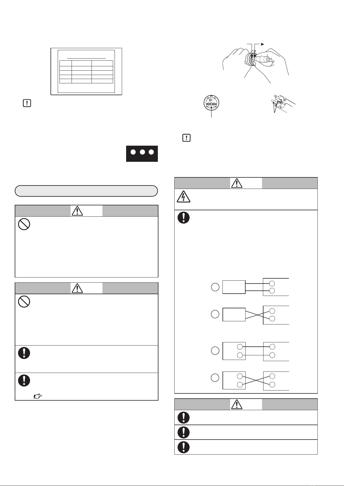
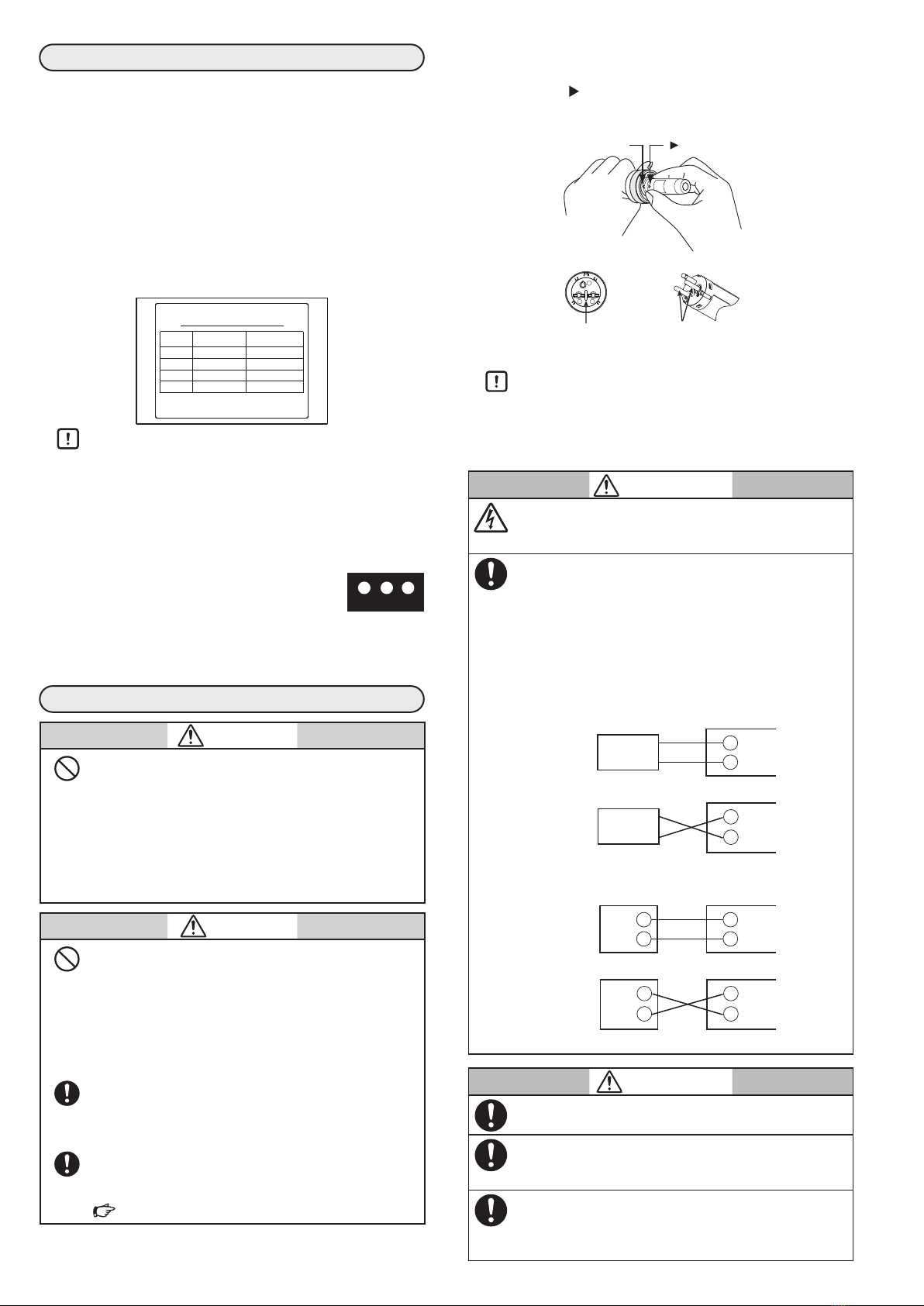
(1) Using the FSP136A100 Analog Flame Meter
• If measuring the flame current:
Insert the flame current measurement plug of the
FSP136A100 into the flame current measurement jack of the
burner controller.
• If measuring the flame voltage:
Connect the red and black flame voltage measurement
probes from the FSP136A100 to the + and - flame voltage
output terminals respectively on the burner controller.
(2) Check the operation of the AUD100/110 by exposing the
AUD15 to a lighter flame or to ultraviolet rays from an ultra-
violet lamp.
Handling Precautions
• Before using an open flame, check that there is no flam-
mable gas in the vicinity.
(3) Mount the AUD100/110 on the monitoring pipe temporarily.
(4) Light the burner.
(5) To determine the optimal monitoring position, measure the
flame current/voltage with the FSP136A100 analog flame
meter while slowly moving the monitoring pipe. Select
the position with the highest possible stable flame current
and voltage which is also within the specified range for the
burner controller.
Fluctuation of the reading within the width of the indicator
needle is OK.
For the specified flame current and voltage range for the
burner controller, see the manual of the burner controller.
lPilot burner turndown test
WARNING
If the flame detector is set so that it detects a pilot
flame that is too small to ignite the main flame, the
AUD100/110 will not be able to recognize (for example)
a flame failure in the main burner. In this case fuel would
continue to be supplied, causing a serious explosion haz-
ard. To prevent this, be sure to do the pilot turndown test
carefully.
If it is necessary to do this test repeatedly, completely
shut down all equipment each time the test is finished,
and completely discharge unburned gas or oil that has
accumulated in the ducts and combustion chamber. If un-
burned gas or oil is not expelled completely, an explosion
may occur.
CAUTION
This test should be done only by a trained and experi-
enced professional.
The purpose of this test is to determine whether, under the least
favorable conditions of gas pressure and air pressure, a pilot flame
detected by the flame detector will reliably light the main burner. For
the procedure of the pilot turndown test, follow the instructions in
the burner controller manual or equipment manufacturer manual.
lIgnition spark response test
WARNING
Make sure that this device does not detect ultraviolet
rays other than those of the burner flame. If it does, a
false flame signal will endanger combustion safety.
Make sure that the flame relay (normally relay 2K) is not af-
fected by the spark generated by the ignition transformer.
This test examines whether this device responds to ultraviolet
rays of the ignition transformer.
For the procedure of the ignition spark response test, follow
the instructions in the burner controller manual or equipment
manufacturer manual.
Final mounting of the monitoring pipe
• When the equipment is operating properly with the specified
flame voltage output after all adjustments have been completed,
turn OFF the power to the equipment, remove the AUD15 and
AUD100/110, and weld the monitoring pipe permanently.
• Mount the AUD15 and AUD100/110 on the monitoring pipe
and do all of the wiring.
• As a guideline for mounting, tighten the nut 1 quarter turn
after contacting the edge of the mounting pipe and the packing
for the nut. Then, check the tightness, include the welding part
of the mounting pipe using a tightness test, etc.
Label attachment
Attach the effective operation time label to a place where it can be
seen easily. Attach the expiration date label to the socket.
Final inspection
To ensure proper burner control, do a trial run of at least one
complete operation cycle of the combustion equipment to verify
that all control operations function correctly.
MAINTENANCE AND INSPECTION
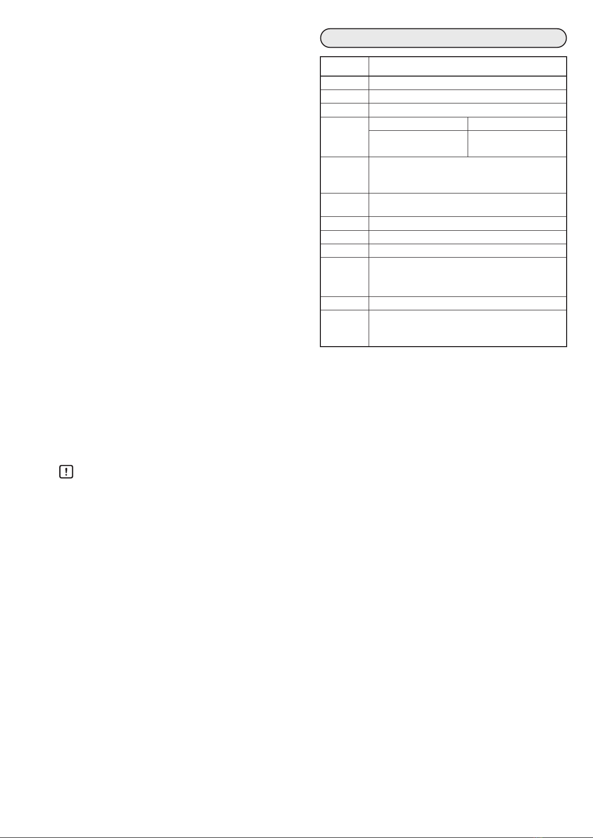
CAUTION
The effective life of the AUD15 is a total of 25,000
hours of use or 5 years (from the date indicated by
the date code on the model No. label).
Be sure to replace it with a new Tube Unit within this
period.
Note. The effective life is the time when UV sensor de-
tects a flame.
Take special care in handling the AUD15 to avoid im-
pact and shock.
When transporting or storing the AUD15, be sure to
put it in a secure packing box.
Maintenance and inspection work for the model
AUD15 and model AUD100/110
lFlame failure test
To check that the flame safeguard control device works prop-
erly, do the flame failure test regularly.
During normal burner combustion, block the monitoring pipe
window so that there is no flame signal, or else cut off the fuel
at the source to extinguish the burner flame. Check that the
flame failure is detected and that the main valve and pilot valve
are closed.
lFlame signal check
Regularly check the flame signal from the burner controller
that is used for batch operation. For the method of checking,
see the user’s manual for the burner controller.

E5
lCheck of the exterior
Check the following regularly.
• Check that the service life of the AUD15 has not expired. If it
has, replace the AUD15 with a new one.
• Check the ambient temperature. The thermolabel can be
used to obtain a rough estimate of the ambient temperature.
If the temperature exceeds the specifications, cool down the
device.
• Check that the nut packing is not damaged. If it is, replace it
with new packing.
• Check that there is no corrosion or damage of the cap nut,
body, terminal block, or lead wires of the AUD100/110. If
any corrosion or damage is found, replace the socket with a
new one.
• Check that AUD15 pins and pin base surface, the
AUD100/110 socket holes, and AUD110 terminals are not
dirty. Replace any dirty component.
lHow to clean the model AUD15
Periodically clean the light-receiving glass surface of the
AUD15 using the following procedure:
(1) Remove the AUD15 and AUD100/110 from the monitor-
ing pipe.
(2) Clean the light-receiving glass surface using a cotton swab
or the like.
(3) Remount the AUD15 and AUD100/110 on the monitoring
pipe.
lHow to replace the model AUD15
(1) To avoid damage to the AUD15, hold the AUD100/110
socket unit and pull it out carefully.
(2) Insert a new AUD15 into the socket (refer to “Inserting
the AUD15 into the AUD100/110” on page E2).
(3) Attach a new effective operation time label and expiration
date label.
Handling Precautions
• Never touch the light-receiving glass surface.
lHow to replace the nut packing
If the nut packing is damaged, replace it according to the pro-
cedure below.
(1) Remove the AUD100/110 from the monitoring pipe.
(2) Hold the main part of the AUD100/110 and, while rotat-
ing the cap nut, move it toward the G 1/2 thread in the
case of the AUD100, or toward the terminal block in the
case of the AUD110. This will detach the nut packing so
that it can be replaced.
(3) Return the cap nut to its original position, and insert the
new nut packing inside the nut, pushing it with an object
that is not sharp to avoid damage.
(4) Remount the AUD100/110 on the monitoring pipe.
SPECIFICATIONS
Item Specifications
Power supply From the burner controller device
Ambient
temperature
-20 to +120°C
Ambient
humidity
40°C, 90% RH max.
Mass AUD100 AUD110
Approx. 120g
(with the AUD15:Approx. 140 g)
Approx. 120g
(with the AUD15:Approx. 140 g)
Insulation
resistance
50MΩ min. by 500 V DC megger
(between each lead wire and the metal part of socket
when the AUD15 is removed)
Protective
structure
IP65 (JIS C 0920/IEC 60529) with pipes and wires connected
Allowable
pressure
35kPa
Vibration
resistance
5m/s2max. (10 to 55Hz for 2 hours each in X, Y and Z
directions)
Mounting nut G1 (R1 and 1-11BSP are connectable)
Lead wires AWG #18 (approx. 1.2mm2) flame retardant cross-linked
polyethylene insulated cable, approx. 1800mm long
(blue and white) (only AUD100)
Conduit G1/2 (1/2-14BSPP is connectable)
Standard and
extended dis-
tance of flame
signal wire
Standard: 2.0mm2, 600 V cable with PVC insulation (“IV
cable”)
Max. length: approx. 200m
China RoHS

E6
1-12-2 Kawana, Fujisawa
Kanagawa 251-8522 Japan
URL: https://www.azbil.com
(11)
Specifications are subject to change without notice.
1st edition: Oct. 2010
10th edition: Oct. 2020 (V)© 2010–2020 Azbil Corporation. All Rights Reserved.
EXTERNAL DIMENSIONS
Model AUD110C100_ with the model AUD15
Unit: mm
(140)
90
Dia. 40
(64) (76) G1/2
52
G1
AUD15
M3.5 terminal screw
AUD main part Terminal
block
Cap nut
Nut packing
60
FG
Model AUD100C100_ with the model AUD15
Unit: mm
(105)
55
(64) (41) G1/2
G1
Dia. 40
Dia. 24
Approx. 1800
AUD15
Lead wire
AUD main part
Cap nut
Nut packing
Nut packing
COMPATIBLE BURNER CONTROLLERS
(sold separately)
Azbil Corporation’s burner controllers
REPLACEMENT/OPTIONAL PARTS
(sold separately)
Model No. Description
AUD15C1000 Tube Unit (Ultraviolet photoelectric tube)
81447479-001 Nut Packing
81403159 Seal adapter
FSP100R15000 Adapter (G1/2 → G1)
FSP136A100 Analog Flame Meter
FSP300C100 Flame simulator
FSP100L70000 Lens unit (the focal distance 70mm)
FSP100L7000D Lens unit (the focal distance 70mm) + Inspection
certificate
FSP100L30000 Lens unit (the focal distance 30mm)
FSP100L3000D Lens unit (the focal distance 30mm) + Inspection
certificate
Dimensions of sealed adapter (model No.
81403159)
Unit: mm
AUD110
Seal adaptor
117
77
18
20
Dia. 42
39 G1
Air purging connection port
PT1/8
Hexagon socket tapered plug
Dimensions of lens unit (model No. FSP100L)
Unit: mm
Air purging connection port
R1/8
Hexagon socket tapered plug
127
112
16
36
Lens unit
G1
Dia. 39
Other manuals for AUD100 Series
2
This manual suits for next models
1
Table of contents
Other Azbil Accessories manuals

Azbil
Azbil SES70 User manual

Azbil
Azbil HTY78 User manual

Azbil
Azbil HP7 Series User manual

Azbil
Azbil K1G Series User manual

Azbil
Azbil HTY 7033 User manual

Azbil
Azbil TY7043D User manual

Azbil
Azbil K1G Series User manual

Azbil
Azbil SES70 User manual

Azbil
Azbil HTY7843 User manual

Azbil
Azbil AUD100 Series User manual
Popular Accessories manuals by other brands

HAMPTON BAY
HAMPTON BAY HB-7903-02 Use and care guide

Crock-Pot
Crock-Pot SMART-PART SP100 owner's guide

Astral Pool
Astral Pool HALO ORP installation manual

Keyautomation
Keyautomation AFT15 manual

FLORABEST
FLORABEST 360594 2007 Assembly, operating and safety instructions

WindowMaster
WindowMaster WWS 100 installation manual