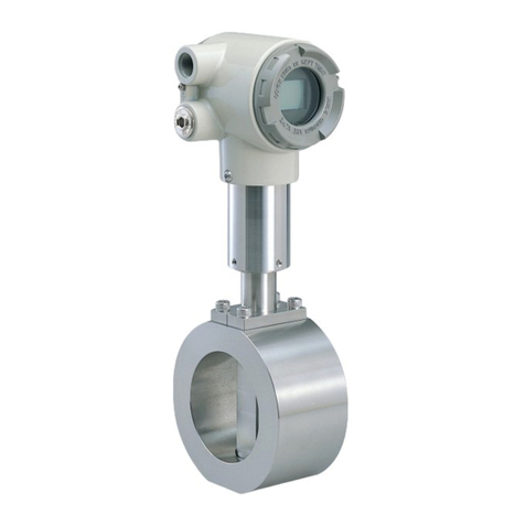
Azbil MagneW 3000 User manual

MagneW
3000 Electromagnetic
Flowmeter
Hyper-Fill
Model: MGR13C (Converter)
MGR11U (Detector)
User’s Manual
CM2-MGR100-2001
2nd edition

Copyright, Notices and Trademarks
© 2005-2012 Azbil Corporation All Rights Reserved.
While this information is presented in good faith and believed to be
accurate, Azbil Corporation disclaims the implied warranties of mer-
chantability and fitness for a particular purpose and makes no express
warranties except as may be stated in its written agreement with and for
its customer.
In no event shall Azbil Corporation be liable to anyone for any indirect,
special or consequential damages. This information and specifications
in this document are subject to change without notice.

Table of Contents
1: Overview..................................................................................1
2: Instrument installation ...........................................................2
2-1: Converter installation............................................................................................ 2
2-2: Detector Installation .............................................................................................. 3
2-3: Wiring ..................................................................................................................... 4
2-3-1: Converter wiring................................................................................................................................. 4
2-3-2: Pulse output wiring ............................................................................................................................ 6
2-3-3: Master-slave wiring............................................................................................................................ 7
3: Configuration of the converter ...............................................8
3-1: Range...................................................................................................................... 8
3-2: Pulse scale ............................................................................................................. 8
3-3: Pulse width............................................................................................................. 9
3-4: Drop out.................................................................................................................. 9
3-5: Master/slave configuration ................................................................................. 10
4: Operation...............................................................................11
4-1: Warm-up ............................................................................................................... 11
4-2: Zero adjustment................................................................................................... 11
4-3: Span adjustment.................................................................................................. 12


Model MGR13C/MGR11U - MagneW3000 Electromagnetic FLowmeter Hyper-Fill 1
1 : Overview
MagneW 3000 Hyper-Fill is developed for high speed batching and filling machine
applications. Hyper-Fill is a magnetic flowmeter optimized for the sophisticated
measurement demands found in filling applications.

Overview Azbil Corporation
2 Model MGR13C/MGR11U - MagneW3000 Electromagnetic FLowmeter Hyper-Fill
2 : Instrument installation
2-1 : Converter installation
(1) Mount the converter by four M4 screws. (M4 screws are not supplied with the
converter.)
(2) Rubber bush is attached to the bracket. Tighten the screws through the rubber bush
and mount the converter. Handle the rubber bush with care because the rubber
bush isolates the converter housing from the mounting wall.
(3) Locate the converter so that switches and terminals face to the front for easy
maintenance.
(4) One converter includes maximum four main boards. Each main board drives each
detector.
~Note • Do not mount the converter in the humid environment.
•Do not mount the converter where water splashes.
Figure 1
Rubber bush
Shield plate
4- 4.5 for M4 screw
φ
[Unit: mm]

Azbil Corporation Overview
Model MGR13C/MGR11U - MagneW3000 Electromagnetic FLowmeter Hyper-Fill 3
2-2 : Detector Installation
(1) Install the detector in the following environment.
Ambient temperature: 5 to 50ºC
Humidity: 5 to 100% RH
(2) The model MGR11U detector is designed using a standard one inch IDF clamp
connection. We recommend to use the welding ferrule that Azbil Corporation
supplies. For the accurate measurement, pipe inner diameter and ferrule inner
diameter connected to the model MGR11U detector should be 15 mm ±0.2 mm.
(3) The detector should be mounted so that the FORWARD end of the flow arrows,
shown on the detector case and water-proof cover, points in the direction of flow
through the tube.
(4) By connecting the special cable model MGA23W, the detector keeps waterproof
performance. Do not splash water before connecting the model MGA23W cable.
(5) After connecting the model MGA23W cable, tighten the screw of the water-proof
connector and tighten the belt of the water-proof cover to keep water and moisture
away.
(6) Detector should be installed where the flowtube will be filled with the fluid and no
air/bubbles will be entrapped.
(7) Install metal pipes to both upstream and downstream side of the detector. To
ensure accurate measurement, install the detector a minimum 15 straight pipe
diameters upstream and two pipe diameters downstream from both ends of the
detector.
15 straight pipe diameters upstream: (upstream side pipe length: 225 mm
minimum)
Two straight pipe diameters downstream: (downstream side pipe length: 30 mm
minimum)
If insulation material tube, such as Teflon® tube is installed in upstream side, a
minimum 20 straight pipe diameters (300 mm minimum) of metal pipe should be
attached to the upstream of the detector.
(8) To ensure precise measurement, inner pipe diameter should be 15mm +/-0.2mm.

Overview Azbil Corporation
4 Model MGR13C/MGR11U - MagneW3000 Electromagnetic FLowmeter Hyper-Fill
2-3 : Wiring
2-3-1 : Converter wiring
Refer to the Table 1 and perform wiring. Turn off the power during wiring.
Connect the wires to the terminals of A1 to A4, B1 to B4 and C1 to C4 at first.
After connecting wires to the terminals of A1 to A4, B1 to B4 and C1 to C4, install the
shield plate as shown in the Figure 1.
The shield plate is fixed by two screws. Refer to the following table for the screw
position.
Figure 2
Left side screw position Right side screw position
between CLKOUT- and A1 between C4 and P1-
Belt
Belt
Water-proof
cover
Water-proof
cover
Water-proof
connector
Water-proof
cover
Case
Electrode
Detector
Flow
direction
arrow
Flow
direction
arrow

Azbil Corporation Overview
Model MGR13C/MGR11U - MagneW3000 Electromagnetic FLowmeter Hyper-Fill 5
~Note 1) Perform earth ground for the power supply (terminal E), for safety
purpose.
2) To ensure accurate measurement, connect master-slave cable between
CLKOUT+/- and CLKIN+/-.
3) Pulse output is open collector type. Make sure to connect external
power supply for the pulse output.
Table 1
Symbol Connect to Meaning
H, N, E Connect to power supply. E for
earth ground. (85 to 264V AC)
Power supply and earth
ground
A1, B1, C1,
X1, Y1
Connect to the special cable model
MGA23Wfor main unit 1
Flow rate signal
Excitation
A2, B2, C2,
X2, Y2
Connect to the special cable model
MGA23W for main unit 2
Flow rate signal
Excitation
A3, B3, C3,
X3, Y3
Connect to the special cable model
MGA23W for main unit 3
Flow rate signal
Excitation
A4, B4, C4,
X4, Y4
Connect to the special cable model
MGA23W for main unit 4
Flow rate signal
Excitation
P1+, P1- Connect to pulse receiving
instrument
Pulse output for main unit 1
(Open Collector)
P2+, P2- Connect to pulse receiving
instrument
Pulse output for main unit 2
(Open Collector)
P3+, P3- Connect to pulse receiving
instrument
Pulse output for main unit 3
(Open Collector)
P4+, P4- Connect to pulse receiving
instrument
Pulse output for main unit 4
(Open Collector)
CLKOUT+,
CLKOUT-
Synchronized signal output from a
master converter and to a slave
converter
Synchronized signal output from a
slave converter to another slave
converter
Synchronized signal output
CLKIN+,
CLKIN-
Synchronized signal input from a
master converter and to a slave
converter
Synchronized signal input from a
slave converter to another slave
converter
Synchronized signal input
Overview Azbil Corporation
6 Model MGR13C/MGR11U - MagneW3000 Electromagnetic FLowmeter Hyper-Fill
2-3-2 : Pulse output wiring
The pulse output is an open collector output. Pay attention to voltage and polarity
when wiring.
External power supply voltage 12 to 24V DC (30V max.)
Output current 100 mA max.
Transient response 5 μS typ.
Power supply
voltage
Voltage drop (closed
circuit) (HIGH voltage)
Voltage drop (Open
circuit) (LOW voltage)
24V DC 19V min. 2.5V max.
12V DC 7V min. 2.5V max.
Figure 3 Wiring diagram for pulse output
This is impossible.
External power supply
12 to 24V DC (30V DC max.)
100mA max.
P
P
Protective diode
Load

Azbil Corporation Overview
Model MGR13C/MGR11U - MagneW3000 Electromagnetic FLowmeter Hyper-Fill 7
2-3-3 : Master-slave wiring
If the Hyper-Fill flowmeter is installed more than five units, Hyper-Fill flowmeters
consist of one master converter and slave converters.
To ensure accurate measurement, the magnetic interference should be negligible in the
multiple head filling machine applications.
Master-slave cable carries synchronized signal for excitation so as to minimize
magnetic interference.
Each converter should be connected with the “Master-slave” cable.
Number of units of the
detector
Number of unit of the
Master converter
Number of unit of the
Slave converter
One to four units One unit Zero
More than five units One unit One unit or more
Figure 4
Master
converter
Slave
converter
Slave
converter
Slave
converter
Master-slave cable

Overview Azbil Corporation
8 Model MGR13C/MGR11U - MagneW3000 Electromagnetic FLowmeter Hyper-Fill
3 : Configuration of the converter
Refer to the following configuration table printed to the main unit for the converter
configuration.
3-1 : Range
Select an appropriate range. It is recommended to set a range so that the flow rate is
approximately 70%. Do not set a range of which the flow rate is less than 25%.
Select the range by receptacles in S2 shown in Figure 5.
3-2 : Pulse scale
0.1 mL/P or 0.05 mL/P is selectable as a pulse scale.
Pulse scale of 0.05 mL/P is not applicable in case of range of 800 mL/s.
~Note * Pulse width of 200
μ
S is not applicable in case that pulse span fre-
quency fs is 8000 Hz.
Figure 5
Range 100 mL/s 200 mL/s 400 mL/s 800 mL/s
Pulse span
frequency fs
0.05 mL/P 2000 Hz 4000 Hz 8000 Hz * N/A
0.1 mL/P 1000 Hz 2000 Hz 4000 Hz 8000 Hz *
S2
S3 S4
100mL/s
100mL/s
200mL/s
200mL/s
400mL/s
400mL/s
800mL/s
800mL/s
RANGE
PULSE WEIGHT
RANGE
PULSEWIDTH
0.1mL/P
0.05mL/P 0.05mL/P 0.05mL/P
0.1mL/P 0.1mL/P 0.1mL/P
30μs 200μs

Azbil Corporation Overview
Model MGR13C/MGR11U - MagneW3000 Electromagnetic FLowmeter Hyper-Fill 9
3-3 : Pulse width
30 μS or 200 μS is selectable as a pulse width.
Transient response of pulse output: 5 μs typ
Pulse width of 200 μs is not applicable in case that pulse span frequency fs is 8000 Hz.
(refer to “3-2 : Pulse scale”)
3-4 : Drop out
Adjustable from 0 to 10% of setting range. This function is used to set the dropout
value for the pulse output. The pulse output will be cut off below the setting value to
avoid flow pulsation in range value close to zero, thus preventing incorrect totalization
of the flow rate. Pulse counting pauses when the flow rate reaches this preset
percentage of the set range. Drop out is set by adjusting variable resistor. Default
setting is approximately two percent. If pulse is still output even though the valve is
shut off, fluid may pulsate. Set the drop out value as approximately five percent.
Pulse width Toler an ce
30 μs30μS ± 4 μs
200 μs200μS ± 22 μs

Overview Azbil Corporation
10 Model MGR13C/MGR11U - MagneW3000 Electromagnetic FLowmeter Hyper-Fill
3-5 : Master/slave configuration
This function is used to minimize magnetic interference by detectors installed closely
each other in the multiple head filling machine applications. A master converter sends
synchronized signal for excitation to slave converters, thus avoiding output error due
to magnetic interference.
According to the model number selected, the configuration for a master or slave is
done by the factory.
Master converter: MGR13C-**M
Slave converter: MGR13C-**S
In case of configuring master/slave function, follow below procedure.
(1) Turn OFF the power.
(2) Loosen screws of the main unit fixed in slot 1 and remove the main unit.
(3) Set the DIP switch as shown in the Figure 6.
Figure 6
MS
1234 1234
Master converter Slave converter

Azbil Corporation Overview
Model MGR13C/MGR11U - MagneW3000 Electromagnetic FLowmeter Hyper-Fill 11
4 : Operation
After configuration, follow below procedures before operation.
4-1 : Warm-up
Turn ON the power.
For accurate measurement, the electronics needs 30-minute warm-up time to stabilize.
Once turn OFF the power and turn ON the power again, wait for 10-minute for
electronics warm-up.
In this case, remove bubbles and verify no bubbles remain inside of the flowtube.
Bubbles will prevent accurate measurement.
4-2 : Zero adjustment
A zero adjustment is very important for accurate flow rate measurement.
Follow the procedures according to the version of the main unit.
Version 1 (ZERO: Variable resistor)
(1) Fill the fluid inside of the flowtube and verify the fluid stops.
(2) Zeroing the flowmeter.
Connect a digital voltmeter or tester between CHECK+ and CHECK- terminals of
the main unit.
Adjust the variable resistor so that the voltage measured by the digital voltmeter
becomes 0 ±20 mV.
Figure 7
Version 1
Version 1
(ZERO:Variable resistor)
Version 2
Version 2
(PLS ZERO: button)

Overview Azbil Corporation
12 Model MGR13C/MGR11U - MagneW3000 Electromagnetic FLowmeter Hyper-Fill
Version 2 (PLS ZERO: button)
(1) Fill the fluid inside of the flowtube and verify the fluid stops.
(2) Zeroing the flowmeter. Push the button of the PLS ZERO for one second. Zero
adjustment will be done automatically. If zero adjustment is done successfully,
LED lights out for five seconds then light on. If failed, LED blinked for 20
seconds. Check if wiring is correct and no bubble remains in the flowtube, and try
zero adjustment again.
Version 2 is compatible with Version 1. Version 1 can be replaced with the version 2.
4-3 : Span adjustment
Span adjustment was performed at the factory. If there is some discrepancy between
actual filling value and flowmeter measured value, tune the span by the “SPAN”
variable resistor.
Figure 8
5s
LED operation in case of correct zero adjustment
LED operation in case of incorrect zero adjustment
1s
1s
20s blink

Note


Document Number: CM2-MGR100-2001
Document Name: MagneW 3000 Electromagnetic Flowmeter
Hyper-Fill
Model: MGR13C / MGR11U
User’s Manual
Date: 1st edition: Mar. 2005
2nd edition: Aug. 2012
Issued/Edited by: Azbil Corporation

This manual suits for next models
2
Table of contents
Other Azbil Measuring Instrument manuals

Azbil
Azbil MVF Series User manual

Azbil
Azbil NWA300 User manual

Azbil
Azbil Micro Flow CMS9500 User manual

Azbil
Azbil mF CMG Series User manual

Azbil
Azbil MVC10A User manual

Azbil
Azbil SR100 User manual

Azbil
Azbil SPG Series User manual

Azbil
Azbil AUR355 Use and care manual

Azbil
Azbil 700 series User manual

Azbil
Azbil mF MVF Series User manual

Azbil
Azbil V8 User manual

Azbil
Azbil SR Series User manual

Azbil
Azbil MagneW FLEX+ User manual

Azbil
Azbil AUR355 User manual

Azbil
Azbil MCF Series User manual

Azbil
Azbil MCW400A100 User manual

Azbil
Azbil CML 050 User manual

Azbil
Azbil mF MCF User manual

Azbil
Azbil MagneW FLEX+ User manual

Azbil
Azbil MagneW Neo PLUS User manual