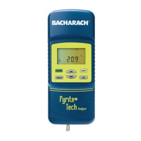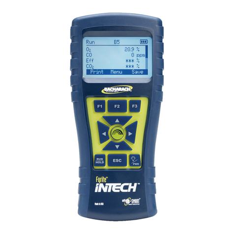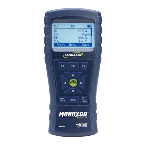
Fyrite
INSIGHT
Plus Manual
0024-9487 Rev 2 v
4.2. Sampling Point Examples .................................................................... 61
4.3. Combustion Testing Process ............................................................... 64
4.4. The RUN Screen .................................................................................. 66
4.5. Making a Draft or Pressure Measurement ......................................... 68
4.6. Printing Using the Optional IrDA Printer............................................. 69
4.7. Graphics Screens................................................................................. 72
4.7.1. Overview................................................................................... 72
4.7.2. Graphical Line Graph Trend Screen .......................................... 73
4.7.3. Bar Graph Screen ...................................................................... 74
4.7.4. Stack Temperature Hot Spot Screen......................................... 77
4.8. Taking Ambient CO Measurements (Siegert Only) ............................. 77
4.9. PC Interface and FyriteUser Software.............................................. 78
SECTION 5. CALIBRATION AND MAINTENANCE .........................................79
5.1. Serviceability....................................................................................... 79
5.2. Cleaning the Probe.............................................................................. 79
5.2.1. Equipment Required ................................................................. 80
5.2.2. Procedure ................................................................................. 80
5.3. Water Trap and Filter Replacement.................................................... 81
5.4. O2and/or CO Sensor Replacement..................................................... 82
5.4.1. Accessing the Sensors............................................................... 82
5.4.2. Material Required (As Needed) ................................................ 82
5.4.3. O2Sensor Replacement Procedure........................................... 82
5.4.4. CO Sensor Replacement Procedure.......................................... 83
5.4.5. B-SMARTCO Sensor Replacement.......................................... 85
5.5. Pressure Sensor Calibration ................................................................ 86
5.5.1. Materials Required ................................................................... 86
5.5.2. Procedure ................................................................................. 86
5.6. T-Stack Calibration .............................................................................. 88
5.6.1. Materials Required ................................................................... 88
5.6.2. T-Stack Calibration Procedure .................................................. 88
5.7. T-Air Calibration .................................................................................. 90
5.7.1. Materials Required ................................................................... 90
5.7.2. T-Air Calibration Procedure ...................................................... 91
5.8. CO Sensor Calibration ......................................................................... 93
5.8.1. Materials Required ................................................................... 93
5.8.2. CO Manual Zero Procedure ...................................................... 93
5.8.3. CO Sensor Span Procedure ....................................................... 94
5.9. T-Ref Sensor Calibration ..................................................................... 95
SECTION 6. TROUBLESHOOTING ............................................................... 96
www.GlobalTestSupply.com
Find Quality Products Online at: sales@GlobalTestSupply.com
