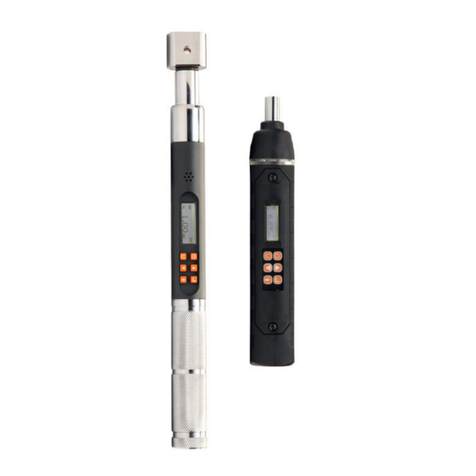
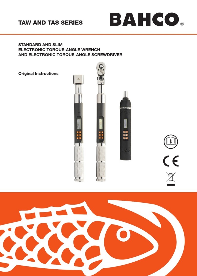
Bahco TAWM1412M User manual

1
Original Instructions
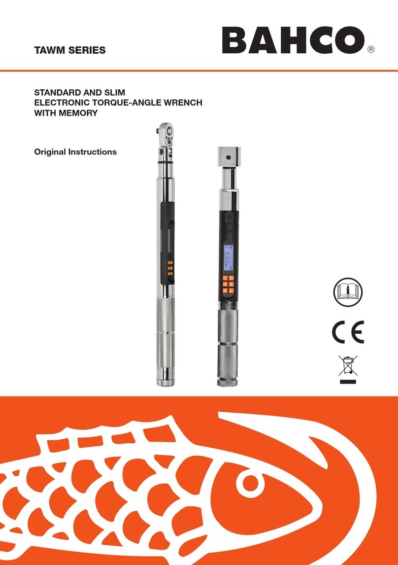
TAWM SERIES
STANDARD AND SLIM
ELECTRONIC TORQUE-ANGLE WRENCH
WITH MEMORY


3
TAWM SERIES
WARNING.
RISK OF FLYING PARTICLES.
Over-torquing can cause breakage.
Force against ex stops on ex
head can cause head breakage. An
out of calibration angle wrench can
cause part or tool breakage. Broken
hand tools, sockets or accessories
can cause injury. Excess force can
cause crowfoot or are nut wrench
slippage.
• Read this manual completely before
using ELECTRONIC WRENCH.
• To insure accuracy, work must not
move in angle mode.
• For personal safety and to avoid
wrench damage, follow good profes-
sional tool and fastener installation
practices.
•Periodic recalibration is necessary to
maintain accuracy.
• Wear safety goggles, user and
bystanders.
• Be sure all components, including
all adaptors, extensions, drivers
and sockets are rated to match or
exceed torque being applied.
• Observe all equipment, system and
manufacturer’s warnings, cautions
and procedures when using this
wrench.
• Use correct size socket for fastener.
• Do not use sockets showing wear or
cracks.
• Replace fasteners with rounded
corners.
• To avoid damaging wrench: Never
use wrench with power off.Always
turn ON wrench so applied torque is
being measured.
• Do not press POWER while torque is
applied or while wrench is in motion.
• Never use this wrench to break
fasteners loose.
• Do not use extensions, such as a
pipe, on handle of wrench.
• Check that wrench capacity matches
or exceeds each application before
proceeding.
• When using negative offsets, verify
maximum targets are not exceeded
(see tables on page 6).
• Verify calibration if dropped.
• Make sure ratchet direction lever is
fully engaged in correct position.
• Verify calibration of wrench if you
know or suspect its capacity has
been exceeded.
• Do not force head of ex head drives
against stops.
• Always adjust your stance to prevent
a possible fall should something give
while using wrench.
• Do not attempt to recharge Alkaline
cells.
• Store wrench in dry place.
• Remove batteries when storing
wrench used for periods longer than
3 months.
WARNING.
Electrical Shock Hazard.
Electrical shock can cause injury.
Metal handle is not isolated.
Do not use on live electrical circuits.
SAVE THESE INSTRUCTIONS
DISCLAIMER
Operation of the wrench is not warranted in an
EU member state if operating instructions are
not in that State’s language.
Contact BAHCO if a translation is needed.
IMPORTANT SAFETY INSTRUCTIONS

TAWM SERIES
HEAD TYPE
Square drive 48 teeth
9x12, 14x18 & 24x32 receivers for interchange-
able head
DISPLAY
• DISPLAY TYPE:
Dot Matrix LCD (192 x 65 Resolution) STD
Dot Matrix LCD (168 x 48 Resolution) SLIM
• VIEWING DIRECTION: 6:00
• BACKLIGHT: WHITE (LED)
SEALED BUTTON PAD
POWER - ON/OFF and torque and angle
re-zero
ENTER - measurement mode select and
menu entry
UP – increments torque and angle settings
and menu navigation
DOWN - decrements torque and angle set-
tings and menu navigation
UNITS - units select: ft-lbs, in-lbs, in-oz
(depending on range); kgm, kg-cm, dNm,
cNm (depending on range) and enter PSET
(preset) menu
LCD BACKLIGHT – Illuminates all screens
and last peak torque or angle recall
FUNCTIONS
• Set - torque or angle target
• Track - real time display of torque or accumu-
lated angular rotation with progress lights
•Peak Hold - 5 sec. ashing of peak torque or
alternating peak torque/angle on release of
torque
• Peak Recall - display last peak torque or peak
torque/angle on button press
• Memory - display of last 1500 peak torque or
peak torque/angle readings
ACCURACY
• Temperature: 22°C (72°F)
• Angle: ±1% of reading ±1º angular velocity
> 10º/sec < 180º/sec
STD CW CCW
Torque:
(unexed)
±2% ±3% of reading, 20% to
100%
of full scale
±4% ±6% of reading, 10% to
19%
of full scale
±8% ±10% of reading, 5% to 9%
of full scale
SLIM CW CCW
Torque:
(unexed)
±2% ±3% of reading, 20% to
100%
of full scale
±4% ±6% of reading, 5% to
19%
of full scale
OPERATING TEMPERATURE
0°F - 130°F (-18°C - 54°C)
STORAGE TEMPERATURE
0°F to 130°F (-18°C to 54°C)
MEASUREMENT DRIFT
ANGLE: -0.12 Angular Degrees per Degree C
TORQUE: +0.01% of reading per Degree C
HUMIDITY
Up to 90% non-condensing
BATTERY
SLIM: Single “AA” Alkaline Cell
STD: Three “AA”Alkaline Cells
Alkaline or rechargeable NiMH batteries ex-
ceeds ASME battery life requirement of 10 hours
continuous operation.
DEFAULT AUTO SHUT-OFF
After 2 minutes idle –
(Adjustable, see Advanced Settings)
SPECIFICATIONS

5
Install fresh Alkaline “AA” cells into handle of wrench.
WRENCH POWER ON SEQUENCE
Note: Do not turn on wrench while torque is applied, otherwise torque zero offset will be incorrect
and wrench will indicate a torque reading when torque is released. If this occurs, re-zero wrench by
momentarily pressing POWER button while wrench is on a stable surface with no torque applied.
1. Turn On Wrench.
While holding wrench still, press POWER button. BAHCO logo will be displayed followed by torque and
angle re-zeroing screens (if angle mode has been previously selected). If real-time-clock has not been
set, date and time entry screens are displayed (see Advanced Conguration section for entering date
and time). After entering date and time or if time has been previously set, target TORQUE or ANGLE
screen will now be displayed (depending on previous measurement mode selected).
2. Select Measurement Mode.
Toggle between target TORQUE andANGLE screens by repeatedly pressing ENTER button.
STD
USER INSTRUCTIONS
FIGURE 1
BATTERY
CONDITION
DATA
STORAGE
ALERT
USB
CONNECTOR
PROGRESS
LIGHTS
PROGRESS
LIGHTS
TORQUE AND/OR
ANGLE DISPLAY
MODE
COUNT ON/OFF AND
RE-ZERO
BUTTON
UNITS AND
PRESET ENTRY
BUTTON
INCREMENT
BUTTON
DECREMENT
BUTTON
MODE SELECTAND
MENU ENTRY BUTTON
LCD BACKLIGHT
AND PEAK
TORQUE/ANGLE
RECALL BUTTON
AUDIBLE
ALERT
PROGRESS LIGHTS
Yellow:
First light indicates 40% of
target torque or angle
reached, Second
indicates 60% of target
reached, Third indicates
80% of target reached.
Green:
Indicates target torque or
angle reached.
Red:
Indicates exceeded
torque or angle target
plus 4% or exceeded
maximum Preset target.

TAWM SERIES
SLIM
Note: When date and time is set for rst time, In-Service date is also set and is used for calculating
initial calibration interval (see “Setting Calibration Interval” in Advanced Conguration section).
Note: If wrench is powered up in torque only measurement mode, angle is not zeroed until mode is
changed to angle measurement mode, at which time torque and angle zeroing begins automatically
after 2 seconds. Wrench should be placed on a stable surface with no torque applied.
Note: Pressing ENTER button while angle is zeroing will abort zeroing function to allow user to
select another measurement mode.
TORQUE MODE
1. Set Target.
Use UP/DOWN buttons to change TORQUE target value.
2. Select Units of Measure.
Repeatedly press UNITS button while on target TORQUE screen until desired units are displayed.
3. Apply TORQUE.
Grasp center of handle and slowly apply torque to fastener until progress lights display green and a
½ second audible alert and handle vibration alerts you to stop.
4. Release TORQUE.
Note peak TORQUE reading ashing on LCD display for 5 seconds. Pressing BACKLIGHT button
while peak torque is ashing will continue to display value until button is released. Momentarily
pressing UP/DOWN, ENTER or UNITS button will immediately return to target TORQUE screen.
Reapplying TORQUE will immediately start another TORQUE measurement cycle.
5. Recall Peak TORQUE Reading.
To recall last peak TORQUE measurement, press and hold BACKLIGHT button for approximately 3
seconds. Peak TORQUE will ash for 5 seconds.

7
ANGLE MODE
Note: When angle measurement mode is selected for rst time following a power on, “ANGLE
ZERO REQUIRED” message is displayed. After two seconds angle zero process begins and
wrench must be placed on a stable surface. If ENTER button is pressed before two seconds to
change to torque only mode, angle zero process is skipped.
1. Set target. Use UP/DOWN buttons to change target ANGLE value.
2. Apply Torque and Rotate Wrench. Grasp center of handle and slowly apply torque to fastener and
rotate wrench at a moderate consistent speed until progress lights display green and a ½ second
audible alert and handle vibration alerts you to stop.
3. Release torque. Note alternating peak TORQUE and ANGLE readings ashing on LCD display for 5
seconds. Pressing BACKLIGHT button while peak values are ashing will continue to display values
until button is released. Momentarily pressing UP/DOWN, ENTER or UNITS button will immediately
return to target ANGLE screen. Reapplying torque (ratcheting) before target screen is displayed will
continue ANGLE accumulation as wrench is rotated.
4. Recall PeakANGLE Reading. To recall last peakANGLE measurement, press and hold BACKLIGHT
button for approximately 3 seconds. Peak TORQUE and ANGLE will be displayed alternately for 5
seconds.
MODE CYCLE COUNT
Mode cycle count feature is used to indicate number of times wrench has reached target torque in
torque measurement mode or target angle in angle measurement mode.
STD / SLIM
TORQUE AND ANGLE MODE CYCLE COUNTING
1. Numerical counter located in top right of target torque or target angle screen will increment after each
torque or angle cycle if applied torque or angle has reached target value.
2. When toggling between torque mode or angle mode using ENTER button or if target is changed,
numerical counter will reset back to 00. counter WILL NOT reset when re-zeroing, on menu entry/
exit or power down.
3. Memory icon will turn on indicating at least one torque or angle cycle data has been stored in memory.
DATA DOWNLOAD
Torque and Angle data in memory can be downloaded to a computer via USB port.
Note: When downloading data from a wrench that has previous downloaded data, rename
previous le or move it to a different directory to prevent overwrite. However, Windows®will
notify user of duplicate le names and allow user to skip download, overwrite existing le or
save new le as a second copy.

TAWM SERIES
1. Connect supplied USB cable from computer to wrench.
2. Computer will display “AutoPlay” window showing TORQLOG as a disk drive with option of using
Windows Explorer to view les:
3. Click “Open Folder” selection to display TORQLOG Character Separated Value (.csv) le.
Note: If “AutoPlay” does not start automatically, use Explorer to display TORQLOG drive contents.
4. Open le using Microsoft Excel by double clicking on le name (Example: “1213590002.CSV”) or
“drag and drop” le to computer.
5. Data on wrench can be cleared by deleting le on the TORQLOG drive.

9
MAIN MENU
Main menu displays wrench operational information.
1. From target torque or angle screen, press and hold ENTER button for 3 seconds.
2. Use UP/DOWN buttons to highlight menu selection then press ENTER button.
Menu Selections:
EXIT - Exits Main menu and returns to target screen.
SET HEAD LENGTH - Displays wrench head length entry screen.
SHOW DATA - Displays stored torque and angle data.
CLEAR DATA - Clears stored torque and angle data.
CYCLE COUNT - Displays torque/angle cycle count screen.
LANGUAGE - Displays language selection menu.
SETTINGS - Displays advanced settings menu (see Advanced Settings Section).
CONFIGURE - Displays advanced conguration menu (see Advanced Conguration Section).
SETTING HEAD LENGTH
Note: If wrench has an interchangeable head or an adapter or extension is added, length of
head, adapter and/or extension being used can be entered to correct for a different length
without requiring re-calibration.
1. To enter a head length, from target torque or angle screen, press and hold ENTER button for 3
seconds.
2. With SET HEAD LENGTH menu selection highlighted, momentarily press ENTER button.
3. Set Head Length screen is displayed next. Default head length is length of head at calibration
(zero for xed head wrench) and is displayed with most-signicant digit highlighted. Use UP/
DOWN buttons to increment/decrement head length. Pressing and holding UP/DOWN buttons will
progressively increment/decrement value faster.
4. Press ENTER button to accept digit and highlight next-signicant digit.
5. Default units of length is in inches. Press UNITS button to change to millimeters.
6. Pressing ENTER button after least-signicant digit is set returns to main menu. If length is changed
from default, «OFFSET IN USE» message will be displayed. Press the ENTER button to display the
target screen. The target torque is highlighted in black.
Note: If UP/DOWN buttons are pressed simultaneously while on the Set Head Length screen,
displayed head length resets to zero or calibration head length for interchangeable head wrenches.
STD

TAWM SERIES
SLIM
Note: For a xed length head, head length entered is offset length measured from center of
drive to center of fastener.
Note: For an interchangeable head, head length is measured from locking pin to center of drive.
SET HEAD LENGTH is set during calibration. If a different length head is used, enter new head
length and offset is calculated automatically.
Note: For an interchangeable head with an adapter, head length entered is sum of head length
and offset length.
USE OF NEGATIVE OFFSETS
Note: Enter a negative value for offset when used in reverse direction with ex head or when
calculating sum of interchangeable head and offset lengths.
Offset
Offset

11
800 Nm wrench:
Maximum Target Torque = offset *7,6 + 800
Offset (cm) Max Target (Nm)
-1 792
-2 785
-3 777
-4 770
When length of an offset (or sum of head minus offset for interchangeable head) is negative, maximum
fastener target is limited by following formulas:
STD
SLIM
Note: When using a negative offset, entering a target torque greater than maximum values
above may cause an overtorque error before reaching fastener target torque and possibly
damage wrench.
VIEWING STORED TORQUE AND ANGLE DATA
Torque data is stored in memory after each torque cycle if applied torque has reached target value.
Torque and angle data is stored in memory after each angle cycle if applied angle has reached target
value. Memory Indicator is displayed when data is stored in non-volatile memory.
1. To view stored torque and angle data, from target torque or angle screen, press and hold ENTER
button for 3 seconds.
2. Highlight SHOW DATA menu selection by pressing UP/DOWN buttons then press ENTER button to
display Show Data screen.
340 Nm wrench:
Maximum Target Torque = offset *6,1 + 340
Offset (cm) Max Target (Nm)
-1 334
-2 328
-3 322
-4 316
135 Nm wrench:
Maximum Target Torque = offset *4,1 + 135
Offset (cm) Max Target (Nm)
-1 131
-2 127
-3 123
-4 119
12 Nm wrench:
Maximum Target Torque = offset * 0,522 + 12
Offset (cm) Max Target (Nm)
-1 11.48
-2 10.96
-3 10.43
-4 9.91
30 Nm wrench:
Maximum Target Torque = offset * 1.3 + 30
Offset (cm) Max Target (Nm)
-1 28.70
-2 27.40
-3 26.10
-4 24.80

TAWM SERIES
3. In Show Data screen, scroll through each stored data record by pressing UP/DOWN buttons.
Example:
0002 = Show Data List Counter: TQ = Peak torque value
0001 = Show Data List Counter: TQ = Peak torque value:ANG = Peak angle value
4. Pressing ENTER button while on Show Data screen returns to main menu.
STD
SLIM
Note: A maximum of 1500 data records can be stored. Memory full icon will be displayed when
full and no more data is stored until memory is cleared.
DELETING STORED TORQUE AND ANGLE DATA
1. From target torque or angle screen, press and hold ENTER button for 3 seconds.
2. Highlight CLEAR DATA menu selection using UP/DOWN buttons then press ENTER button to
display CLEAR ALL DATA screen.
3. In CLEAR ALL DATA screen, highlight YES menu selection to delete all stored data, or NO menu
selection to exit without deleting data.
4. Press ENTER button after making selection.
Note: If wrench is Locked (see Preset Lock in Advanced section), Clear Data function is disabled.

13
STD
SLIM
VIEWING AND CLEARING WRENCH CYCLE COUNTER
Each time torque or angle target is reached, wrench cycle counter is incremented. Maximum cycle
count is 999999.
1. From target torque or angle screen, press and hold ENTER button for 3 seconds.
2. Highlight CYCLE COUNT menu selection using UP/DOWN buttons.
3. Press ENTER button to display CYCLE COUNT screen.
4. To exit CYCLE COUNT screen without clearing count, press ENTER button while EXIT menu
selection is highlighted.
5. To reset wrench cycle count to 0, highlight CLEAR menu selection then press ENTER button.
6. EXIT menu selection is automatically highlighted after count is cleared. Press ENTER button to
return to main menu.
STD
SLIM

TAWM SERIES
Note: If wrench is Locked (see Preset Lock in Advanced section) Clear count function is disabled.
LANGUAGE
1. To select the language menu, press the ENTER button while LANGUAGE is highlighted then
highlight the desired language and press the ENTER button.
2. Decimal Mark selection menu is displayed. Decimal separator can be a comma or decimal point.
Use UP/DOWN buttons to select the decimal separator then press the ENTER button.
Note: The decimal separator will affect the formatting of the downloaded data when opened by
Excel depending on Windows®regional settings.
STD
SLIM
3. To exit Main menu and return to target torque or angle screen, press ENTER button while EXIT
menu selection is highlighted.
TARGET PRESETS (PSET)
PSET function gives user ability to congure 50 preset target torque or target angle settings, each with
a target, minimum, maximum (over range) and batch count value. PSETs are stored in non-volatile
memory so that they are retained while power is off.
Note: After adding a Preset (see below), navigate between manual target torque, angle mode
and PSET screen by repeatedly pressing ENTER button. While PSET screen is displayed, press
UP/DOWN buttons to select additional congured PSETs.

15
STD
SLIM
ADDING A TORQUE PRESET
1. From manual target torque screen, select units of measure.
2. Press and hold UNITS button for 3 seconds.
3. ADD PRESET conrmation screen is displayed. Highlight YES menu selection using UP/DOWN
buttons then press ENTER button. NO menu selection returns to main menu without adding a PSET.
4. TARGETTORQUE screen is displayed.TARGET TORQUE is target value of fastener. Initial TARGET
TORQUE value is value from target torque screen.TARGET TORQUE can be set to any value within
wrench torque range by pressing UP/DOWN buttons. Once desired target torque value has been
set, press ENTER button.
5. MINIMUM TORQUE screen is displayed. MINIMUM TORQUE is value at which green progress
lights, audible alert and vibrator turn on. Initial MINIMUM TORQUE value is TARGET TORQUE value
minus negative torque tolerance (default 0%, see MODE SETUP in Advanced Conguration section).
MINIMUM TORQUE can be set to any value from TARGET TORQUE to wrench minimum torque range
bypressingUP/DOWNbuttons.Once desired minimumtorquevaluehasbeenset, press ENTERbutton.

TAWM SERIES
6. MAXIMUM TORQUE screen is displayed next. MAXIMUM TORQUE is torque value above which
red progress lights turn on. Initial MAXIMUM TORQUE value will be TARGET TORQUE value plus
positive torque tolerance (default 4%, see MODE SETUP in Advanced Conguration section).
Maximum torque value can be set greater than TARGET TORQUE value to 10% above wrench
maximum range by pressing UP/DOWN buttons. Once desired maximum torque value has been set,
press ENTER button.
7. BATCH COUNT screen is displayed next. Default value is zero. Batch count range is 0 to 99. Press
UP/DOWN buttons to increment/decrement batch count. Mode Count increments each time target
torque is reached if a batch count of zero is entered. Mode Count decrements if a non-zero batch
count is entered and resets to batch count value when count reaches zero. Once desired batch
count value has been set, press ENTER button.
8. PSET target screen is displayed labeled with next available PSET number from 01 to 50.
9. To enter additional torque presets, repeatedly press ENTER button until target torque screen is
displayed and repeat steps above.
STD
SLIM
ADDING AN ANGLE PRESET
1. From manual target angle screen, press and hold UNITS button for 3 seconds.
2. ADD PRESET conrmation screen is displayed. Highlight YES menu selection using UP/DOWN buttons
then press ENTER button. NO menu selection returns to main menu without adding a PSET.
3. TARGET ANGLE screen is displayed. TARGET ANGLE is fastener rotational angle target value. Initial
TARGETANGLE value is value from target angle screen.TARGETANGLE can be set from 0 to 360° by
pressing UP/DOWN buttons. Once desired target angle value has been set, press ENTER button.
4. MINIMUM ANGLE screen is displayed. MINIMUM ANGLE is value at which green progress lights, au-
dible alert and vibrator turn on. Initial MINIMUMANGLE value is TARGETANGLE minus negative angle

17
tolerance (default 0%, see MODE SETUP in Advanced Conguration section). MINIMUM ANGLE can be
set from 0 to TARGETANGLE by pressing UP/DOWN buttons. Once desired minimum angle value has
been set, press ENTER button.
5. MAXMUMANGLE screen is displayed next. MAXIMUM ANGLE is angle value above which red progress
lights turn on. Initial MAXIMUMANGLE value will be TARGET ANGLE plus positive angle tolerance (de-
fault 4%, see MODE SETUP in Advanced Conguration section). MAXIMUM ANGLE value can be set to
any value greater than TARGETANGLE by pressing UP/DOWN buttons. Once desired value has been
set, press ENTER button.
6. BATCH COUNT screen is displayed next. Default value is zero. Batch count range is 0 to 99. Press UP/
DOWN buttons to increment/decrement batch count. Mode Count increments each time target angle is
reached if a batch count of zero is entered. Mode Count decrements if a non-zero batch count is entered
and resets to batch count value when count reaches zero. Once desired batch count value has been set,
press ENTER button.
7. PSET target screen is displayed labeled with next available PSET number from 01 to 50.
8. To enter additional angle presets, repeatedly press ENTER button until target angle screen is displayed and
repeat steps above.
STD
SLIM
EDITING A PRESET
Edit PSET function gives user ability to edit stored PSETS on wrench.
1. From Preset screen to be edited, press and hold UNITS button for 3 seconds.
2. CHANGE PRESET screen is displayed.

TAWM SERIES
3. Highlight EDIT selection using UP/DOWN buttons then press ENTER button.
4. TARGET TORQUE or TARGET ANGLE screen is displayed. Value can be changed by pressing UP/
DOWN buttons. Once desired target torque or angle value has been set, press ENTER button.
5. MINIMUM TORQUE or MINIMUM ANGLE screen is displayed. Value can be changed by pressing
UP/DOWN buttons. Once desired torque or angle value has been set, press ENTER button.
6. MAXMUM TORQUE or MAXIMUM ANGLE screen is displayed next. Value can be changed by
pressing UP/DOWN buttons. Once desired torque or angle value has been set, press ENTER button.
7. BATCH COUNT screen is displayed next. Value can be changed by pressing UP/DOWN buttons.
Once desired batch count value has been set, press ENTER button.
8. PSET target screen is displayed labeled with same PSET number.
STD
SLIM
Note: Pressing ENTER button while EXIT menu selection is highlighted will exit without editing
PSET.
DELETING A PRESET
Delete PSET function allows user to remove stored presets from wrench
1. From Preset screen to be deleted, press and hold UNITS button for 3 seconds.
2. CHANGE PRESET screen is displayed.
3. Highlight DELETE menu selection using UP/DOWN buttons and press ENTER button.
4. Target screen is displayed and deleted PSET is no longer available for selection.

19
Note: Pressing ENTER button while EXIT menu selection is highlighted will exit without deleting PSET.
Note: When a PSET is deleted, all other stored PSET’s will retain their original PSET numbers.
When a new PSET is entered, it will be assigned rst available PSET number in sequence.
STD SLIM
ADVANCED SETTINGS
Advanced settings are accessed from SETTINGS menu selection on main menu.
1. From target torque or angle screen, press and hold ENTER button for 3 seconds.
2. Highlight SETTINGS menu selection using UP/DOWN buttons.
3. Press ENTER button to display Settings menu.
Menu Selections:
EXIT - Exits Settings menu and returns to target screen.
SHOW INFO - Displays wrench operational information.
SLEEP TIME - Displays power down interval setup screen.
LCD CONTRAST - Displays LCD contrast setup screen.
KEY BEEP - Displays button press beep enable/disable setup screen.
TARGET BEEP - Displays target beep enable/disable setup screen (only on SLIM wrenches).
AUTO BACKLIGHT - Displays auto backlight enable/disable screen to turn on backlight during
measurement.
TOGGLE BACKLGHT - Displays BACKLIGHT button toggle or timeout enable/disable screen.
VIBRATOR CONFIG - Displays vibrator ON/OFF conguration for when target reached.
BATTERY TYPE - Displays the battery type selection screen (only on SLIM wrenches).
4. To exit Settings menu and return to target torque or angle screen, press ENTER button while EXIT
menu selection is highlighted.
STD

TAWM SERIES
SLIM
Note: All user congurable settings are stored in non-volatile memory and are retained while
power is off.
SHOW INFO
Show Info menu selection displays wrench operational information.
1. From Settings menu, press ENTER button while SHOW INFO selection is highlighted.
2. SHOW INFO screen is displayed.
3. UP/DOWN buttons are used to scroll screen.
Operational Information:
SN: Serial number assigned to wrench.
CAL: Date of last wrench calibration.
ISD: In-Service Date.
TCF: Torque Calibration Factor.
ACF: Angle Calibration Factor.
VER: Software version.
OVR CNT: Overtorque Counter tracks how many times an over-torque event occurred on wrench
(torque >125% of full scale).
TQZ: Torque Zero Offset.
AZZ: Angle Z-Axis Zero Offset (only on SLIM wrenches).
AZX: Angle X-axis Zero Offset (only on SLIM wrenches).
AZO: Angle Zero Offset at full scale torque (only on SLIM wrenches).
TFS: Torque full scale value (only on SLIM wrenches).
AZO+: Angle Zero Offset at CW Torque Full Scale (only on STD wrenches).
AZO-: Angle Zero Offset at CCW Torque Full Scale (only on STD wrenches).
TFS+: CW Torque Full Scale (only on STD wrenches).
TFS-: CCW Torque Full Scale (only on STD wrenches).
Copyright.
4. Pressing ENTER button exits Show Info screen and returns to Settings menu.
STD SLIM
This manual suits for next models
1
Table of contents
Languages:
Other Bahco Power Tools manuals

Bahco
Bahco P-SL User manual

Bahco
Bahco BCL32IW1 User manual

Bahco
Bahco IZO-DM User manual

Bahco
Bahco 7454 User manual

Bahco
Bahco TAW Series User manual

Bahco
Bahco BCL33IW1 User manual

Bahco
Bahco WPTC Series User manual

Bahco
Bahco Ratchet Combination Wrench User manual

Bahco
Bahco BCL31R1 User manual

Bahco
Bahco TASMB Series User manual