Bahco WPTC Series User manual

1
Original Instructions
WPTC


3
IMPORTANT SAFETY INSTRUCTIONS
WARNING.
RISK OF FLYING
PARTICLES.
Over-torquing can cause
breakage. Force against ex
stops on ex head can cause
head breakage. An out of
calibration angle tool can
cause part or tool breakage.
Broken hand tools, sockets
or accessories can cause
injury. Excess force can
cause crowfoot or are nut
tool slippage.
• Read this manual
completely before using
ELECTRONIC TOOL.
• To insure accuracy, work
must not move in angle
mode.
• For personal safety and to
avoid tool damage, follow
good professional tool
and fastener installation
practices.
• Periodic recalibration is
necessary to maintain
accuracy.
• Wear safety goggles, user
and bystanders.
• Be sure all components,
including all adaptors,
extensions, drivers and
sockets are rated to match
or exceed torque being
applied.
• Observe all equipment,
system and manufacturer’s
warnings, cautions and
procedures when using this
tool.
• Use correct size socket for
fastener.
• Do not use sockets showing
wear or cracks.
• Replace fasteners with
rounded corners.
• To avoid damaging tool:
Never use tool with power
off. Always turn ON tool
so applied torque is being
measured.
• Do not press POWER while
torque is applied or while
tool is in motion.

WPTC
• Never use this tool to break
fasteners loose.
• Do not use extensions, such
as a pipe, on handle of tool.
• Check that tool capacity
matches or exceeds
each application before
proceeding.
• Verify calibration if dropped.
• Make sure ratchet direction
lever is fully engaged in
correct position.
• Verify calibration of tool
if you know or suspect
its capacity has been
exceeded.
• Do not force head of ex
head drives against stops.
• Always adjust your stance
to prevent a possible fall
should something give while
using tool.
• Do not attempt to recharge
Alkaline cells.
• Store tool in dry place.
• Remove batteries when
storing tool used for periods
longer than 3 months.
WARNING.
Electrical Shock Hazard.
Electrical shock can cause
injury. Metal handle is not
isolated.
Do not use on live electrical
circuits.
SAVE THESE
INSTRUCTIONS
DISCLAIMER
Operation of the tool is not
warranted in an EU member
state if operating instructions
are not in that State’s
language.
Contact BAHCO if a
translation is needed.

5
WPTC (2.4GHZ) TORQUE WRENCH OPERATING INSTRUCTIONS
Models to which these instructions apply:
WPTC-5 WPTC-15 WPTC-25 WPTC-60
WPTC-100 WPTC-200 WPTC-300 WPTC-400
WPTC 2.4 GHz torque wrenches are designed and manufactured to provide consistent
torque application in multiple manufacturing and maintenance applications. They meet or
exceed the requirements of ASME B107.300 and ISO 6789. These wrenches are accurate
to +/-4% of the preset value from 20% to 100% of rated capacity.
Interchangeable Heads
Any Bahco interchangeable head may be used with the wrench. Note: It is imperative that
the head used to preset the torque wrench have the same common centerline length as
the head that will be used in assembly. Failure to do so will create a different torque output
during assembly than that which was preset.
Torque Setting
A torque tester of +/- 1% indicated value
accuracy or better, an especial Combination
Adjusting and Release Tool (CART) (shown
at right), and an interchangeable head
having the same common centerline length
as the head that will be used in assembly
and capable of engaging the tester are
required.
Torque
Adjustment
Key
Locking Key

WPTC
1. Insert the Torque Adjustment Key fully into the rear of
the wrench so the hex engages the adjustment nut. Do
not engage the Lock Key. Rotate the Torque Adjustment
Key slightly clockwise to disengage the adjustment nut
from the lock nut.
2. Slide the Lock Key in until it engages the lock nut. You
may need to rotate the lock key slightly to align it with
the internal hex of the lock nut. Rotate the Lock Key
counterclockwise several turns to assure the lock nut is
fully disengaged from the adjustment nut and that there
is sufcient travel available for the adjustment nut to
attain the torque setting desired.
3. Install the interchangeable head on the wrench. Engage
the wrench to the tester and click the wrench once or
twice while noting the readings. To adjust the wrench
to a higher torque setting, rotate the Torque Adjustment
Key clockwise. To adjust the wrench to a lower torque
setting, rotate the Torque Adjustment Key counter-
clockwise. Torque adjustments should be made in small
increments with several checks made between each
movement of the Torque Adjustment Key.
4. Once the desired torque has been attained, hold the Torque Adjustment Key steady and
rotate the Lock Key clockwise until the lock nut rmly engages the torque adjustment
nut, locking it in place. Remove the CART from the wrench and perform a nal torque
check on the tester. When the reading matches the desired torque and the lock nut is
rmly engaged to the torque adjustment nut, the procedure is complete.
Radio Communications - 2.4 GHz Communication Overview
These tools use the 2.4GHz band for communication with the controller. As with all
radio communications, there are limits on the distance at which reliable bi-directional
communication may be obtained. Physical barriers such as steel framing, sheet metal and

7
other objects that impede radio waves can signicantly reduce the reliable communication
distance. Another factor affecting the reliability and distance combination is the radio
environment in which the unit will be used.
The controller and torque wrench may operate on any of the 12 channels these products
use. It is generally best to think about this even before the unit is installed.
The radio modules in the controllers and torque wrenches used with them comply with the
IEEE 802.15.4 standard. The channel numbers loosely match the channels used by the
IEEE 802.11b/g WLAN standard. It may be benecial to use channels that do not match the
channels used by a nearby wireless network. The graph below depicts both standards and
illustrates the center frequencies and channel overlap for each standard.
Notice that the channels we use leave a much smaller footprint than WLAN. Also notice
that one WLAN channel radiates energy onto several of the adjacent WLAN and process
monitor (PM) channels.
For the most reliable communication
between the Bahco PM and the tool in a
802.11b/g LAN environment, it is usually
best to choose a channel for the controller
and tool that is separated from the channel
of the LAN.
Unlike IEEE 802.15.1 (Bluetooth) radios,
our 2.4GHz radio modules do not frequency
hop, use less power and have faster
response times with less impact on other
wireless devices. A wrench only transmits
a small packet of data after each torque
operation, and each transmission lasts
about 30ms (0.03 seconds).
The 2.4GHz radio used by the unit and the
tool is certied in the United States (FCC),
Canada (IC), and Europe (CE).
Torque wrenchoutputpower: 1mw
Controller 2.4GHz output power: 10-60mw
Typical 802.11b/goutput power: 100mw
Frequency Map of 802.15.4 vs. 802.11b/g
Center Frequency (GHz)
Channel 802.15.4 802.11b/g
1 2.410 2.412
2 2.415 2.417
3 2.420 2.422
4 2.425 2.427
5 2.430 2.432
6 2.435 2.437
7 2.440 2.442
8 2.445 2.447
9 2.450 2.452
10 2.455 2.457
11 2.460 2.462
12 2.465

WPTC
Establishing RF Communication With Bahco Process Monitors
The transceiver in the PM and the one in the torque wrench each have identication
numbers. When communication between the two is rst established, the numbers are
exchanged and stored in memory. The PM and tool will thereafter ignore communications
from other radios until the number stored in memory is replaced with a different identication
number.
The second element is that under all conditions the controller and the tool to be used with it
must be on the same channel. If the channel on the controller is changed and the channel on
the tool is not, they will not communicate or will cease communicating if they have previously
been associated with each other.
To remove the identication of the unit from the tool memory, click the wrench and hold it
in the clicked position until the LED on the wrench ashes. This will take about 5 seconds.
Release the pressure on the tool and allow it to return to the normal position.
The ashing of the LED occurs when the Process Monitor with which the tool was associated
has been erased. The tool is now ready to be associated with another PM\.
Note that when the battery has been removed and replaced in the wrench the LED will
alternate between emitting red and green light several times very quickly. If the alternating
color emission stops and then a red light pulse is emitted, the tool is not associated with
a specic controller and can be associated with whatever unit is desired. If the alternating
color emission stops and then a green light pulse is emitted, the tool has a specic controller
unit identication number in memory and is ready to be used with that unit.
To establish communication with the controller, it is necessary to follow the instructions
included with the specic controller to be used.
Raised LED Fresnel emits Green or Red during the “learning in” or
radio connection process.
Even when faceplate is tilted away from the user the raised Fresnel
is easily seen.
Battery and Battery Replacement
These tools are shipped with an alkaline battery. Always respect polarity requirements for
our tools.
1. The battery compartment is located directly under the LED on the underside of the
wrench. Turn the wrench over so the face plate is facing the oor.

9
2. Use a pen head or small screwdriver to
depress the battery cover security spring
and slide the battery cover plate off.
3. Remove the old battery and recharge it.
4. Reinstall the battery and battery cover.
5. Note: We strongly urge that NiMH
rechargeable AAA batteries are the
only battery used in these products.
Other batteries have different operating
characteristics and are highly unlikely to
provide satisfactory performance.
Radio Transceiver Replacement
Under normal circumstances the transceiver is well protected and the system is robust and
durable. This procedure should only be needed on rare occasions.
1. Remove the four screws in the radio
housing and gently lift the cover straight
up off of the internal components.
2. The radio board is now visible.
Notice the location of the spring steel
trigger on the micros witch (red arrow
on right). The trigger location is critical
to tool function. The screw rising from
inside the wrench (indicated by red
arrow on left) triggers the micros witch
that activates the electronic functions. When the electronics are reassembled the trigger
must be on the inside of this screw for the tool to function.
3. Gently lift the circuit board off of the mounting plate without damaging the gray insulating
paper between it and the mounting plate. The insulating paper is essential to preventing
shorts on the circuit board. Examine the paper for tears and replace if torn or damaged
4. Reassemble the components in the reverse order oft heir removal. Place the circuit
board on the insulating paper on the mounting plate, ensuring that the micros witch
trigger is inside the activating screw. Install the upper cover and screws holding it in
place. Then install the battery in the battery holder and slide the battery cover back to
the original position.
Operation & LED’s
Once the tool has been preset, the appropriate interchangeable head installed and the
radio transceiver has been associated with the appropriate controller and specications
exchanged, the tool is ready for use. In normal operation, the tool will emit a strong tactile
and sound impulse when it clicks. If the tool is jerked (too little time in the clicked position)
the LED on the tool will not illuminate. If the tool has been properly used (force applied,
click attained, force released within specied time frame) the LED on the circuit board will
WPTC
illuminate with a green color. This will shine through the cover and be highly visible. If the
tool has been pulled past the click (too much time in the clicked position) the LED on the
circuit board will illuminate with a red color. Under either of the latter two circumstances, the
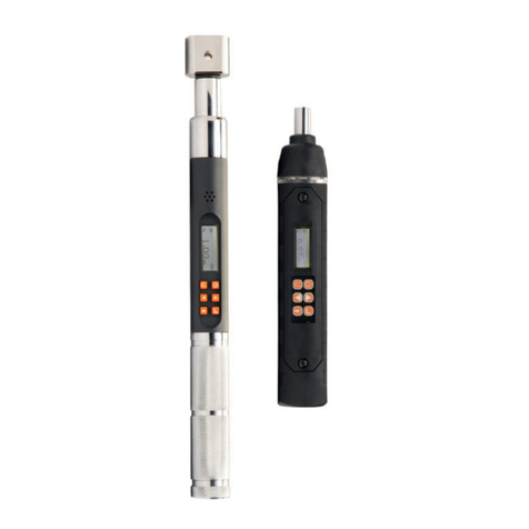
information will be immediately transmitted to the controller.
Reversible ratchet heads
Even though the ratchet is reversible, the tool only applies measured and controlled torque
in the clockwise direction, so thought must be given to the task to be accomplished before
the ratchet is reversed and the tool used in the counter-clockwise direction. Exceeding the
capacity of the tool in a CCW torque application is likely to damage the tool and is not
covered by warranty.
Cleaning
This wrench should be cleaned with a soft cloth dampened with water. Do not immerse this
tool in liquid or use any solvent other than water to clean the tool.
Presetting, Calibration and Repair
Presetting from our Internal After Sales Centers is available. Contact your Bahco distributor
for details. Parts and factory repair are also available.
INSTRUCTION TO THE USER
This equipment has been tested and found to comply with the limits for a class B digital
device, pursuant to part 15 of the FCC Rules. These limits are designed to provide reasonable
protection against harmful interference in a residential installation. This equipment
generates, uses and can radiate radio frequency energy and if not installed and used in
accordance with the instructions, may cause harmful interference to radio communications.
However, there is no guarantee that interference will not occur in a particular installation. If
this equipment does cause harmful interference to radio or television reception, which can
be determined by turning the equipment off and on, the user is encouraged to try to correct
the interference by one or more of the following measures:
• Reorient or relocate the receiving antenna.
• Increase the separation between the equipment and receiver.
• Connect the equipment into an outlet on a circuit different from that to which the receiver
is connected..
• Consult the dealer or an experienced radio/TV technician for help.
This equipment has been certied to comply with the limits for a class B computing device,
pursuant to FCC Rules. Operation with non-approved equipment is likely to result in
interference to radio and TV reception. The user is cautioned that changes and modications
made to the equipment without the approval of manufacturer could void the user’s authority
to operate this equipment.

11
(ENG) EC DECLARATION OF CONFORMITY
(FRA) DÉCLARATION DE CONFORMITÉ CE
(ESP) DECLARACIÓN DE CONFORMIDAD DE LA CE
(POR) DECLARAÇÃO DE CONFORMIDADE EC
(ITA) DICHIARAZIONE DI CONFORMITA’CE
(GER) EG-KONFORMITÄTSERKLÄRUNG
(NED) EG- VERKLARING VAN OVEREENSTEMMING
(POL) EC DEKLARACJA ZGODNOŚCI
(SWE) CE DEKLARATION
(DEN) EF-VERENSSTEMMELSESERKLÆRING
(NOR) ECSAMSVERKLARING
(FIN) EY-VAATIMUSTENMUKAISUUSVAKUUTUS
(RUS) Декларация о соответствии EC
(TUR) CE STANDARDİZASYON BEYANI
(CZE) PROHLÁŠENÍ O SHODĚ
(SVK) PREHLÁSENIE O ZHODE
(GRE) ΔΗΛΩΣΗ ΣΥΜΜΟΡΦΩΣΗΣ ΜΕ ΕΕ
(ENG) Hereby declares that: / The device:
(FRA) Déclare par la présente que: / L´appareil:
(ESP) Declaro que: / El aparato:
(POR) Vimos por este meio declarar: / O aparéelo:
(ITA) Con la presente dichiaro che: / Dispositivo:
(GER) Hiermit wird erklärt, dass: / Die folgenden Erzeugnisse:
(NED) Hierbij verklaart dat: / Het apperaat:
(POL) Niniejszym oświadcza, że: / Urządzenia:
(SWE) Härmed deklareras att: / Enheten:
(DEN) Erklærer herved at: / enheten:
(NOR) Erklærer herved at: / enheten:
(FIN) Vakuutamme täten: / Että tuote:
(RUS) Настоящим заявляем, что: / Устройство:
(TUR) Beyan ederiz ki: / Cihaz:
(CZE) Níže prohlašujeme, že: / výrobek:
(SVK) Týmto prehlasujeme, že : / Výrobok:
(GRE) Δηλώνει ότι: / Η συσκευή:
(ENG) Was manufactured in conformity with the provisions in the:
(FRA) A été fabriqué en conformité avec les dispositions des:
(ESP) Está fabricada según las disposiciones de:
(POR) Foi fabricado em conformidade com os pressupostos:
(ITA) Prodotto in conformità con le disposizioni:
(GER) In Übereinstimmung mit den Bestimmungen der:
(NED) Is vervaardigd in overeenstemming met de bepalingen in de:
(POL) Został wyprodukowany zgodnie z przepisami:
(SWE) Producerats enligt bestämmelserna i följande direktiv:
(DEN) Produsert i samsvar med bestemmelsene i:
(NOR) Produsert i samsvar med bestemmelsene i:
(FIN) On valmistettu noudattaen säännöksiä:
(RUS) Было произведено в соответствии с положениями:
(TUR) Aşağıdaki Standartlara uygun üretilmiştir:
(CZE) Byl vyroben ve shodě s předpisy:
(SVK) Bol vyrobený v zhode s predpismi:
(GRE) Κατασκευάστηκε σύμφωνα με τις διατάξεις του:
(ENG) Type(s)
(FRA) Type(s)
(ESP) Tipo(s)
(POR) Tipo
(ITA) Tipo
(GER) Type(s)
(NED) Typen
(POL) Typ
(SWE) Typ
(DEN) Typ
(NOR) Typ
(FIN) Tyyppi
(RUS) Тип
(TUR) Tip
(CZE) Typ
(SVK) Typ
(GRE) Τύπος:
WPCU2S
WPTC-5
WPTC-15
WPTC-25
WPTC-60
WPTC-100
WPTC-200
(ENG) Person authorized to compile the technical le (TCF):
(FRA) Personne autorisée à constituer le dossier technique:
(SPA) Persona facultada para elaborar el expediente técnico:
(POR) Pessoa autorizada para elaborar o dossier técnico:
(ITA) Persona autorizzata a compilare la pratica tecnica
(GER) Bevollmächtigte(r) zum Zusammenstellen technischer Unterlagen:
(NLD) Persoon die is gemachtigd het technisch dossier samen te stellen
(POL) Osoba odpowiedzialna za zestawianie pliku technicznego
(SWE) Person som är behörig att sammanställa den tekniska dokumentationen:
(DAN) Person bemyndiget til at udarbejde tekniske beskrivelser:
(NOR) Autorisert person for utarbeidelse av den tekniske len:
(FIN) Henkilö on valtuutettu kokoamaan teknisen tiedoston
(TUR) Teknik dosyayı düzenlemeye yetkili kişi:
(RUS) Лицо, уполномоченное на составление технической документации:
(CZE) Autorizovaná osoba pro sestavení technického spisu:
(SLO) Osoba zodpovedná za vypracovanie technickej dokumentácie:
(GRE) Άτομο εξουσιοδοτημένο να καταρτίσει τον τεχνικό φάκελο
Sergio
Calvo
Antigua ctra. Altube Km 5,5 - 01196 Arangiz, SPAIN
(ENG) Year
(FRA) Année
(ESP) Año
(POR) Ano
(ITA) Anno
(GER) Baujahr
(NED) Jaar
(POL) Rok
(SWE) År
(DEN) År
(NOR) År
(FIN) Vuosi
(RUS) Год
(TUR) Sene
(CZE) Rok
(SVK) Rok
(GRE) Χρόνος:
2018
2018/11/5
SNA EUROPE – 16 Allé Rosa Luxemburg, Eragny-sur-Oise, 95610 Cergy Pontoise Cedex, France – Phone: +33 1 39099868 – Fax : +33 1 39099881
2014/30/EC; 2011/65/EU; 2012/19/EU
EN 61000-6-2, EN 61000-6-4, EN 61000-4-7, IEC 61000-3-2, IEC 61000-3-3, IEC 61000-4-2, IEC 61000-4-3,
IEC 61000-4-4, IEC 61000-4-5, IEC 61000-4-6, IEC 61000-4-8, IEC 61000-4-11
(ENG) Product
(FRA) Produit
(ESP) Producto
(POR) Produto
(ITA) Prodotto
(GER) Produkt
(NED) Product
(POL) Produkt
(SWE) Produkten
(DEN) Produktet
(NOR) Produktet
(FIN) Tuotteen
(RUS) Изделие
(TUR) Ürün
(CZE) Výrobek
(SVK) Výrobok
(GRE) Προιόν:
Torque wrench and control unit
Clé dynamométrique et unité de contrôle
Llave dinamométrica y unidad de control
Chave de torque e unidade de controle
Chiave dinamometrica e unità di controllo
Drehmomentschlüssel und Steuereinheit
Momentsleutel en besturingseenheid
Klucz dynamometryczny i jednostka sterująca
Momentnyckel och styrenhet
Momentnøgle og styreenhed
Momentnøkkel og styreenhet
Momenttiavain ja ohjausyksikkö
Динамометрический ключ и блок управления
Tork anahtarı ve kontrol ünitesi
Momentový klíč a řídicí jednotka
Momentový kľúč a riadiaca jednotka
Κλειδί ροπής και μονάδα ελέγχου

20-2104-BA REV-2
This manual suits for next models
8
Table of contents
Other Bahco Power Tools manuals

Bahco
Bahco TAW Series User manual

Bahco
Bahco Ratchet Combination Wrench User manual

Bahco
Bahco 6852P User manual

Bahco
Bahco BCL32IW1 User manual

Bahco
Bahco TASMB Series User manual

Bahco
Bahco BCL31R1 User manual

Bahco
Bahco IZO-D User manual

Bahco
Bahco P-SL User manual

Bahco
Bahco IZO-DM User manual

Bahco
Bahco IZO-D User manual