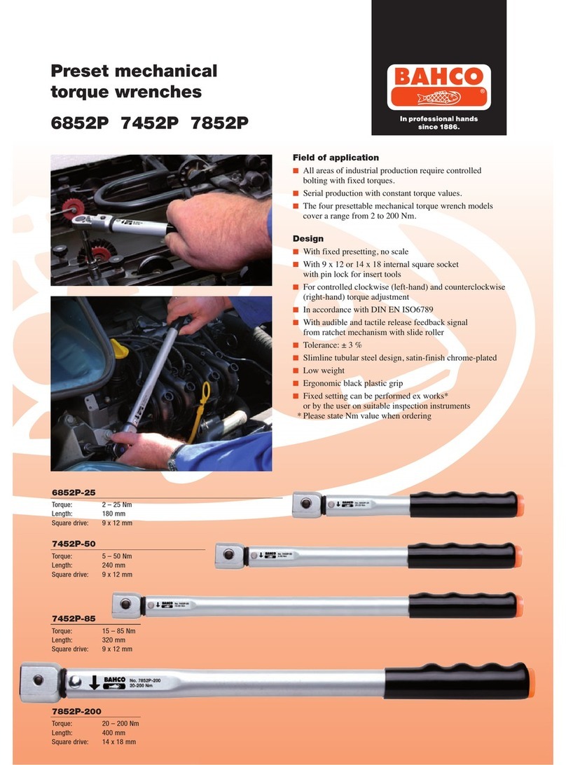
Bahco TASMB Series User manual

1
Original Instructions
TASMB AND TAWMB SERIES
STANDARD AND SLIM
ELECTRONIC TORQUE-ANGLE BLUETOOTH®WRENCH
AND ELECTRONIC TORQUE-ANGLE BLUETOOTH®SCREWDRIVER

TASMB AND TAWMB SERIES
WARNING.
RISK OF FLYING PARTICLES.
Over-torquing can cause
EUHDNDJH)RUFHDJDLQVWÀH[
VWRSVRQÀH[KHDGFDQFDXVH
KHDGEUHDNDJH$QRXWRI
calibration angle tool can
cause part or tool breakage.
%URNHQKDQGWRROVVRFNHWV
or accessories can cause
LQMXU\([FHVVIRUFHFDQFDXVH
FURZIRRWRUÀDUHQXWWRRO
slippage.
• Read this manual completely
before using ELECTRONIC
TOOL.
• To insure accuracy, work must
not move in angle mode.
• For personal safety and to
avoid tool damage, follow good
professional tool and fastener
installation practices.
• Periodic recalibration is
necessary to maintain
accuracy.
• Wear safety goggles, user and
bystanders.
• Be sure all components,
including all adaptors,
extensions, drivers and
sockets are rated to match or
exceed torque being applied.
• Observe all equipment, system
and manufacturer’s warnings,
cautions and procedures when
using this tool.
• Use correct size socket for
fastener.
• Do not use sockets showing
wear or cracks.
• Replace fasteners with
rounded corners.
• To avoid damaging tool: Never
use tool with power off. Always
turn ON tool so applied torque
is being measured.
• Do not press POWER while
torque is applied or while tool
is in motion.
IMPORTANT SAFETY INSTRUCTIONS

3
STANDARD AND SLIM ELECTRONIC TORQUE-ANGLE BLUETOOTH®WRENCH
AND ELECTRONIC TORQUE-ANGLE BLUETOOTH®SCREWDRIVER
• Never use this tool to break
fasteners loose.
• Do not use extensions, such
as a pipe, on handle of tool.
• Check that tool capacity
matches or exceeds each
application before proceeding.
• Verify calibration if dropped.
• Make sure ratchet direction
lever is fully engaged in correct
position.
• Verify calibration of tool if you
know or suspect its capacity
has been exceeded.
• 'RQRWIRUFHKHDGRIÀH[KHDG
drives against stops.
• Always adjust your stance to
prevent a possible fall should
something give while using
tool.
• Do not attempt to recharge
Alkaline cells.
• Store tool in dry place.
• Remove batteries when storing
tool used for periods longer
than 3 months.
WARNING.
(OHFWULFDO6KRFN+D]DUG
(OHFWULFDOVKRFNFDQFDXVH
LQMXU\0HWDOKDQGOHLVQRW
LVRODWHG
Do not use on live electrical
circuits.
SAVE THESE INSTRUCTIONS
DISCLAIMER
Operation of the tool is not
warranted in an EU member
state if operating instructions
are not in that State’s language.
Contact BAHCO if a translation
is needed.

TASMB AND TAWMB SERIES
This equipment has been tested and found to comply with the limits for a Class B digital device, pursu-
ant to Part 15 of the FCC rules.
These limits are designed to provide reasonable protection against harmful interference in a residen-
tial installation.
This equipment generates, uses, and can radiate radio frequency energy and, if not installed and
used in accordance with the instructions, may cause harmful interference to radio communications.
However, there is no guarantee that interference will not occur in a particular installation. If this equip-
ment does cause harmful interference to radio or television reception, which can be determined by
turning the equipment off and on, the user is encouraged to try to correct the interference by one or
more of the following measures:
• Reorient or relocate the receiving antenna.
• Increase the separation between the equipment and receiver.
• Connect the equipment into an outlet on a circuit different from that to which the receiver
is connected.
• Consult the dealer or an experienced radio/TV technician for help.
This device complies with Industry Canada license-exempt RSS standard(s). Operation is subject to
the following two conditions:
(1) This device may not cause interference, and
(2) This device must accept any interference, including interference that may cause undesired opera-
tion of the device.

5
STANDARD AND SLIM ELECTRONIC TORQUE-ANGLE BLUETOOTH®WRENCH
AND ELECTRONIC TORQUE-ANGLE BLUETOOTH®SCREWDRIVER
:5(1&++($'7<3(6
9x12, 14x18 & 24x32 receivers for interchange-
able head
6&5(:'5,9(56&5+($'7<3(6
1/4” female hex earth magnet retention
DISPLAY
• DISPLAY TYPE:
Dot Matrix LCD (192 x 65 Resolution) STD
Dot Matrix LCD (168 x 48 Resolution) SLIM
& SCR
• VIEWING DIRECTION: 6:00
• BACKLIGHT: WHITE (LED)
SEALED BUTTON PAD
POWER - ON/OFF and torque and angle
re-zero
ENTER - measurement mode select and
menu entry
UP – increments torque and angle settings
and menu navigation
DOWN - decrements torque and angle set-
tings and menu navigation
UNITS - units select: ft-lbs, in-lbs, in-oz
(depending on range); kgm, kg-cm, dNm,
cNm (depending on range) and enter PSET
(preset) menu
LCD BACKLIGHT – Illuminates all screens
and last peak torque or angle recall
FUNCTIONS
• Set - torque or angle target
• Track - real time display of torque or accumu-
lated angular rotation with progress lights
• 3HDN+ROGVHFÀDVKLQJRISHDNWRUTXHRU
alternating peak torque/angle on release of
torque
• Peak Recall - display last peak torque or peak
torque/angle on button press
• Memory - display of last 1500 peak torque or
peak torque/angle readings
ACCURACY
• Temperature: 22°C (72°F)
• Angle: (±1% of reading) + (±1º angular
velocity > 10º/sec < 180º/sec) + (±1º of test
¿[WXUH6/,067'
• Angle: (±1% of reading) + (±1° @ angular
velocity > 10°/sec < 180°/sec:) (TAW..) + (±2°
##!DQGRQO\6&5
CW CCW
Torque:
XQÀH[HG
±2% ±3% RIUHDGLQJWR
RIIXOOVFDOH
±4% ±4% RIUHDGLQJWR
RIIXOOVFDOH
OPERATING TEMPERATURE
0°F - 130°F (-18°C - 54°C)
STORAGE TEMPERATURE
0°F to 130°F (-18°C to 54°C)
MEASUREMENT DRIFT
ANGLE: -0.12 Angular Degrees per Degree C
TORQUE: +0.01% of reading per Degree C
+80,',7<
Up to 90% non-condensing
BATTERY
SLIM & SCR: Single “AA” Alkaline Cell
STD: Three “AA” Alkaline Cells
Alkaline, Lithium or rechargeable NiMH
batteries exceeds ASME battery life requirement
of 10 hours continuous operation.
'()$8/7$8726+872))
After 2 minutes idle –
(Adjustable, see Advanced Settings)
Static Dissipative (ESD) Properties: Surface
Resistivity 107-1010 (only in screwdriver (SCR))
SPECIFICATIONS
TASMB AND TAWMB SERIES
SCR
,QVWDOOIUHVK$ONDOLQH³$$´FHOOVLQWRKDQGOHRIWRRO
TOOL POWER ON SEQUENCE
Note: Do not turn on tool while torque is applied, otherwise torque zero offset will be incorrect
and tool will indicate a torque reading when torque is released. If this occurs, re-zero tool by
momentarily pressing POWER button while tool is on a stable surface with no torque applied.
1. Turn On Tool.
While holding tool still, press POWER button. BAHCO logo will be displayed followed by torque and
angle re-zeroing screens (if angle mode has been previously selected). If real-time-clock has not been
VHWGDWHDQGWLPHHQWU\VFUHHQVDUHGLVSOD\HGVHH$GYDQFHG&RQ¿JXUDWLRQVHFWLRQIRUHQWHULQJGDWH
and time). After entering date and time or if time has been previously set, target TORQUE or ANGLE
screen will now be displayed (depending on previous measurement mode selected).
Note: By simultaneously pressing the ENTER and UNITS U buttons, the keypad can be locked
to prevent inadvertent button presses while griping the screwdriver body. The Lock Icon is
displayed when the keypad is locked. To unlock the keypad, press the ENTER – UNITS U –
ENTER buttons in sequence (on screwdrivers (SCR) only).
Note: If the keypad was locked when powered down, on power up, the keypad will remain
locked and will require the keypad unlock button sequence of ENTER – UNITS U – ENTER to
become functional again (on screwdrivers (SCR) only).
6HOHFW0HDVXUHPHQW0RGH
Toggle between target TORQUE and ANGLE screens by repeatedly pressing ENTER button.
USER INSTRUCTIONS
FIGURE 1
FIGURE 1
AUDIBLE
ALERT
352*5(66/,*+76
Yellow:
)LUVWOLJKWLQGLFDWHVRI
WDUJHWWRUTXHRUDQJOHUHDFKHG
6HFRQGLQGLFDWHVRI
WDUJHWUHDFKHG
7KLUGLQGLFDWHVRI
WDUJHWUHDFKHG
Green:
,QGLFDWHVWDUJHWWRUTXHRU
DQJOHUHDFKHG
Red:
,QGLFDWHVH[FHHGHGWRUTXHRU
DQJOHWDUJHWSOXVRU
H[FHHGHGPD[LPXP3UHVHW
WDUJHW
SLIM & STD
352*5(66/,*+76
Yellow:
VHFRQGRQRIIÀDVKLQJ
LQGLFDWHVRIWDUJHWWRUTXH
RUDQJOHUHDFKHGVHFRQG
ÀDVKLQJLQGLFDWHVRI
WDUJHWUHDFKHG&RQWLQXRXV
RQLQGLFDWHVRIWDUJHW
UHDFKHG
Green:
,QGLFDWHVWDUJHWWRUTXHRUDQJOH
UHDFKHG
Red:
,QGLFDWHVH[FHHGHGWRUTXHRU
DQJOHWDUJHWSOXVRU
H[FHHGHGPD[LPXP3UHVHW
WDUJHW
WIRELESS LINK
CONDITION
BATTERY
CONDITION
DATA STORAGE
ALERT
352*5(66
LIGHTS
352*5(66
LIGHTS
72548($1'25
$1*/(',63/$<
MODE
COUNT
212))$1'
RE-ZERO BUTTON
81,76$1'35(6(7
ENTRY BUTTON
INCREMENT
BUTTON
DECREMENT
BUTTON
MODE SELECT AND
MENU ENTRY BUTTON
LCD BACKLIGHT
$1'3($.
72548($1*/(
RECALL BUTTON
WIRELESS LINK
CONDITION
BATTERY
CONDITION
DATA STORAGE
ALERT
USB
CONNECTOR
352*5(66
LIGHTS
352*5(66
LIGHTS
72548($1'25
$1*/(',63/$<
MODE
COUNT 212))$1'
RE-ZERO BUTTON
81,76$1'35(6(7
ENTRY BUTTON
INCREMENT
BUTTON
DECREMENT
BUTTON
MODE SELECT AND
MENU ENTRY BUTTON
LCD BACKLIGHT
$1'3($.
72548($1*/(
RECALL BUTTON
AUDIBLE
ALERT

7
STANDARD AND SLIM ELECTRONIC TORQUE-ANGLE BLUETOOTH®WRENCH
AND ELECTRONIC TORQUE-ANGLE BLUETOOTH®SCREWDRIVER
STD/SLIM
SCR
TORQUE ZEROING
Target Torque Screen Target Angle Screen
180º
00
ANGLE ZEROING
--
SET STILL
LOCK icon 80.00
00
IN-LB
80.00
00
IN-LB 180º
00
IN-LB
ENTER - UNITS - ENTER
keypad unlock sequence
ENTER
button
Note: If wrench is powered up in torque only measurement mode, angle is not zeroed until mode is
changed to angle measurement mode, at which time torque and angle zeroing begins automatically
after 2 seconds. Wrench should be placed on a stable surface with no torque applied.
Note: If screwdriver is powered up in torque only measurement mode, angle is not zeroed until
keypad is unlocked and mode is changed to angle measurement mode. The Angle Zero Required
screen will be displayed. Angle zeroing begins automatically after 2 seconds. Screwdriver should
be placed on a stable surface with no torque applied (on screwdrivers (SCR) only).
Note: Pressing ENTER button while angle is zeroing will abort zeroing function to allow user to
select another measurement mode.
TORQUE MODE
1. Set Target.
Use UP/DOWN buttons to change TORQUE target value.
2. Select Units of Measure.
Repeatedly press UNITS button while on target TORQUE screen until desired units are displayed.

TASMB AND TAWMB SERIES
3. Apply TORQUE.
Grasp center of handle and slowly apply torque to fastener until progress lights display green and a
½ second audible alert and handle vibration alerts you to stop.
4. Release TORQUE.
1RWHSHDN72548(UHDGLQJÀDVKLQJRQ/&'GLVSOD\IRUVHFRQGV3UHVVLQJ%$&./,*+7EXWWRQ
ZKLOH SHDN WRUTXH LV ÀDVKLQJ ZLOO FRQWLQXH WR GLVSOD\ YDOXH XQWLO EXWWRQ LV UHOHDVHG 0RPHQWDULO\
pressing UP/DOWN, ENTER or UNITS button will immediately return to target TORQUE screen.
Reapplying TORQUE will immediately start another TORQUE measurement cycle.
5. Recall Peak TORQUE Reading.
To recall last peak TORQUE measurement, press and hold BACKLIGHT button for approximately 3
VHFRQGV3HDN72548(ZLOOÀDVKIRUVHFRQGV
ANGLE MODE
1RWH:KHQDQJOHPHDVXUHPHQWPRGHLVVHOHFWHGIRU¿UVWWLPHIROORZLQJDSRZHURQ³$1*/(
ZERO REQUIRED” message is displayed. After two seconds angle zero process begins and tool
must be placed on a stable surface. If ENTER button is pressed before two seconds to change
to torque only mode, angle zero process is skipped.
1. Set target. Use UP/DOWN buttons to change target ANGLE value.
2. Apply Torque and Rotate Tool. Grasp center of handle and slowly apply torque to fastener and rotate
tool at a moderate consistent speed until progress lights display green and a ½ second audible alert
and handle vibration alerts you to stop.
5HOHDVHWRUTXH1RWHDOWHUQDWLQJSHDN72548(DQG$1*/(UHDGLQJVÀDVKLQJRQ/&'GLVSOD\IRU
VHFRQGV3UHVVLQJ%$&./,*+7EXWWRQZKLOHSHDNYDOXHVDUHÀDVKLQJZLOOFRQWLQXHWRGLVSOD\YDOXHV
until button is released. Momentarily pressing UP/DOWN, ENTER or UNITS button will immediately
return to target ANGLE screen. Reapplying torque (ratcheting) before target screen is displayed will
continue ANGLE accumulation as tool is rotated.
4. Recall Peak ANGLE Reading. To recall last peak ANGLE measurement, press and hold BACKLIGHT
button for approximately 3 seconds. Peak TORQUE andANGLE will be displayed alternately for 5 seconds.
MODE CYCLE COUNT
Mode cycle count feature is used to indicate number of times tool has reached target torque in torque
measurement mode or target angle in angle measurement mode.
STD / SLIM / SCR
180º
01
M
MODE CYCLE COUNT
MEMORY icon
TORQUE AND ANGLE MODE CYCLE COUNTING
1. Numerical counter located in top right of target torque or target angle screen will increment after each
torque or angle cycle if applied torque or angle has reached target value.
2. When toggling between torque mode or angle mode using ENTER button or if target is changed,
numerical counter will reset back to 00. counter WILL NOT reset when re-zeroing, on menu entry/
exit or power down.
3. Memory icon will turn on indicating at least one torque or angle cycle data has been stored in
memory.

9
STANDARD AND SLIM ELECTRONIC TORQUE-ANGLE BLUETOOTH®WRENCH
AND ELECTRONIC TORQUE-ANGLE BLUETOOTH®SCREWDRIVER
MAIN MENU
Main menu displays tool operational information.
1. From target torque or angle screen, press and hold ENTER button for 3 seconds.
2. Use UP/DOWN buttons to highlight menu selection then press ENTER button.
Menu Selections:
EXIT - Exits Main menu and returns to target screen.
SET HEAD LENGTH - Displays wrench head length entry screen (only on TAWMB wrenches).
SHOW DATA - Displays stored torque and angle data.
CLEAR DATA - Clears stored torque and angle data.
CYCLE COUNT - Displays torque/angle cycle count screen.
LANGUAGE - Displays language selection menu.
SETTINGS - Displays advanced settings menu (see Advanced Settings Section).
&21),*85('LVSOD\VDGYDQFHGFRQ¿JXUDWLRQPHQXVHH$GYDQFHG&RQ¿JXUDWLRQ6HFWLRQ
PAIR STATE - Displays wireless radio pairing state (see Advanced Settings Section)
6(77,1*+($'/(1*7+21/<$33/,&$%/(727$:0%:5(1&+(6
Note: If wrench has an interchangeable head or an adapter or extension is added, length of
head, adapter and/or extension being used can be entered to correct for a different length
without requiring re-calibration.
1. To enter a head length, from target torque or angle screen, press and hold ENTER button for 3
seconds.
2. With SET HEAD LENGTH menu selection highlighted, momentarily press ENTER button.
3. Set Head Length screen is displayed next. Default head length is length of head at calibration
]HUR IRU ¿[HG KHDG ZUHQFK DQG LV GLVSOD\HG ZLWK PRVWVLJQL¿FDQW GLJLW KLJKOLJKWHG 8VH 83
DOWN buttons to increment/decrement head length. Pressing and holding UP/DOWN buttons will
progressively increment/decrement value faster.
3UHVV(17(5EXWWRQWRDFFHSWGLJLWDQGKLJKOLJKWQH[WVLJQL¿FDQWGLJLW
5. Default units of length is in inches. Press UNITS button to change to millimeters.
3UHVVLQJ(17(5EXWWRQDIWHUOHDVWVLJQL¿FDQWGLJLWLVVHWUHWXUQVWRPDLQPHQX,IOHQJWKLVFKDQJHG
from default, «OFFSET IN USE» message will be displayed on target screen (on STD wrenches),
the target torque is highlighted in black (on SLIM wrenches).
Note: If UP/DOWN buttons are pressed simultaneously while on the Set Head Length screen,
displayed head length resets to zero or calibration head length for interchangeable head
wrenches.

TASMB AND TAWMB SERIES
1RWH³2))6(7,186(´VFUHHQLVGLVSOD\HGHDFKWLPHZUHQFKLVUH]HURHGLI6HW+HDG
Length is not equal to calibration head length.
1RWH)RUD¿[HGOHQJWKKHDGKHDGOHQJWKHQWHUHGLVRIIVHWOHQJWKPHDVXUHGIURPFHQWHURI
drive to center of fastener.
Offset
1RWH)RUDQLQWHUFKDQJHDEOHKHDGKHDGOHQJWKLVPHDVXUHGIURPORFNLQJSLQWRFHQWHURIGULYH
6(7+($'/(1*7+LVVHWGXULQJFDOLEUDWLRQ,IDGLIIHUHQWOHQJWKKHDGLVXVHGHQWHUQHZKHDG
length and offset is calculated automatically.
1RWH)RUDQLQWHUFKDQJHDEOHKHDGZLWKDQDGDSWHUKHDGOHQJWKHQWHUHGLVVXPRIKHDGOHQJWK
and offset length.
USE OF NEGATIVE OFFSETS
1RWH(QWHUDQHJDWLYHYDOXHIRURIIVHWZKHQXVHGLQUHYHUVHGLUHFWLRQZLWKÀH[KHDGRUZKHQ
calculating sum of interchangeable head and offset lengths.
Offset
When length of an offset (or sum of head minus offset for interchangeable head) is negative, maximum
fastener target is limited by following formulas:

11
STANDARD AND SLIM ELECTRONIC TORQUE-ANGLE BLUETOOTH®WRENCH
AND ELECTRONIC TORQUE-ANGLE BLUETOOTH®SCREWDRIVER
STD
SLIM
Note: When using a negative offset, entering a target torque greater than maximum values
above may cause an overtorque error before reaching fastener target torque and possibly
damage wrench.
VIEWING STORED TORQUE AND ANGLE DATA
Torque data is stored in memory after each torque cycle if applied torque has reached target value.
Torque and angle data is stored in memory after each angle cycle if applied angle has reached target
value. Memory Indicator is displayed when data is stored in non-volatile memory.
1. To view stored torque and angle data, from target torque or angle screen, press and hold ENTER
button for 3 seconds.
2. Highlight SHOW DATA menu selection by pressing UP/DOWN buttons then press ENTER button to
display Show Data screen.
3. In Show Data screen, scroll through each stored data record by pressing UP/DOWN buttons.
Example:
0002 = Show Data List Counter: TQ = Peak torque value
0001 = Show Data List Counter: TQ = Peak torque value: ANG = Peak angle value
4. Pressing ENTER button while on Show Data screen returns to main menu.
1PZUHQFK
0D[LPXP7DUJHW7RUTXH RIIVHW
Offset (cm) Max Target (Nm)
-1 792
-2 785
-3 777
-4 770
1PZUHQFK
0D[LPXP7DUJHW7RUTXH RIIVHW
Offset (cm) Max Target (Nm)
-1 642
-2 634
-3 626
-4 618
1PZUHQFK
0D[LPXP7DUJHW7RUTXH RIIVHW
Offset (cm) Max Target (Nm)
-1 334
-2 328
-3 322
-4 316
1PZUHQFK
0D[LPXP7DUJHW7RUTXH RIIVHW
Offset (cm) Max Target (Nm)
-1 28.70
-2 27.40
-3 26.10
-4 24.80
1PZUHQFK
0D[LPXP7DUJHW7RUTXH RIIVHW
Offset (cm) Max Target (Nm)
-1 131
-2 126
-3 122
-4 118

TASMB AND TAWMB SERIES
STD
SLIM
SCR
Note: A maximum of 1500 data records can be stored in memory. Memory full icon will be
displayed when full. New data will replace oldest record until memory is cleared.

13
STANDARD AND SLIM ELECTRONIC TORQUE-ANGLE BLUETOOTH®WRENCH
AND ELECTRONIC TORQUE-ANGLE BLUETOOTH®SCREWDRIVER
DELETING STORED TORQUE AND ANGLE DATA
1. From target torque or angle screen, press and hold ENTER button for 3 seconds.
2. Highlight CLEAR DATA menu selection using UP/DOWN buttons then press ENTER button to
display CLEAR ALL DATA screen.
3. In CLEAR ALL DATA screen, highlight YES menu selection to delete all stored data, or NO menu
selection to exit without deleting data.
4. Press ENTER button after making selection.
STD
M
SLIM
Note: If wrench is Locked (see Preset Lock in Advanced section), Clear Data function is disabled.
SCR

TASMB AND TAWMB SERIES
VIEWING AND CLEARING TOOL CYCLE COUNTER
Each time torque or angle target is reached, tool cycle counter is incremented. Maximum cycle count
is 999999.
1. From target torque or angle screen, press and hold ENTER button for 3 seconds.
2. Highlight CYCLE COUNT menu selection using UP/DOWN buttons.
3. Press ENTER button to display CYCLE COUNT screen.
4. To exit CYCLE COUNT screen without clearing count, press ENTER button while EXIT menu
selection is highlighted.
5. To reset tool cycle count to 0, highlight CLEAR menu selection then press ENTER button.
6. EXIT menu selection is automatically highlighted after count is cleared. Press ENTER button to
return to main menu.
STD
SLIM
SCR

15
STANDARD AND SLIM ELECTRONIC TORQUE-ANGLE BLUETOOTH®WRENCH
AND ELECTRONIC TORQUE-ANGLE BLUETOOTH®SCREWDRIVER
LANGUAGE
1. To select the language menu, press the ENTER button while LANGUAGE is highlighted then
highlight the desired language and press the ENTER button.
2. Decimal Mark selection menu is displayed. Decimal separator can be a comma or decimal point.
Use UP/DOWN buttons to select the decimal separator then press the ENTER button.
Note: The decimal separator will affect the formatting of the downloaded data when opened by
Excel depending on Windows®regional settings.
STD
SLIM
SCR
3. To exit Main menu and return to target torque or angle screen, press ENTER button while EXIT
menu selection is highlighted.

TASMB AND TAWMB SERIES
TARGET PRESETS (PSET)
36(7IXQFWLRQJLYHVXVHUDELOLW\WRFRQ¿JXUHSUHVHWWDUJHWWRUTXHRUWDUJHWDQJOHVHWWLQJVHDFKZLWK
a target, minimum, maximum (over range) and batch count value. PSETs are stored in non-volatile
memory so that they are retained while power is off.
Note: After adding a Preset (see below), navigate between manual target torque, angle mode
and PSET screen by repeatedly pressing ENTER button. While PSET screen is displayed, press
83'2:1EXWWRQVWRVHOHFWDGGLWLRQDOFRQ¿JXUHG36(7V
ADDING A TORQUE PRESET
1. From manual target torque screen, select units of measure.
2. Press and hold UNITS button for 3 seconds.
$'' 35(6(7 FRQ¿UPDWLRQVFUHHQ LVGLVSOD\HG +LJKOLJKW<(6PHQX VHOHFWLRQXVLQJ 83'2:1
buttons then press ENTER button. NO menu selection returns to main menu without adding a PSET.
4. TARGET TORQUE screen is displayed. TARGET TORQUE is target value of fastener. Initial
TARGET TORQUE value is value from target torque screen. TARGET TORQUE can be set to any
value within wrench torque range by pressing UP/DOWN buttons. Once desired target torque value
has been set, press ENTER button.
5. MINIMUM TORQUE screen is displayed. MINIMUM TORQUE is value at which green progress lights,
audible alert and vibrator turn on. Initial MINIMUM TORQUE value is value from target torque screen.
MINIMUM TORQUE can be set to any value from TARGET TORQUE to tool minimum torque range by
pressing UP/DOWN buttons. Once desired minimum torque value has been set, press ENTER button.
6. MAXIMUM TORQUE screen is displayed next. MAXIMUM TORQUE is torque value above which
red progress lights turn on. Initial MAXIMUM TORQUE value will be MINIMIUM TORQUE value plus
4%. Maximum torque value can be set greater than TARGET TORQUE value to 10% above wrench
maximum range by pressing UP/DOWN buttons. Once desired maximum torque value has been set,
press ENTER button.
7. BATCH COUNT screen is displayed next. Default value is zero. Batch count range is 0 to 99. Press
UP/DOWN buttons to increment/decrement batch count. Mode Count increments each time target

17
STANDARD AND SLIM ELECTRONIC TORQUE-ANGLE BLUETOOTH®WRENCH
AND ELECTRONIC TORQUE-ANGLE BLUETOOTH®SCREWDRIVER
torque is reached if a batch count of zero is entered. Mode Count decrements if a non-zero batch
count is entered and resets to batch count value when count reaches zero. Once desired batch
count value has been set, press ENTER button.
8. PSET target screen is displayed labeled with next available PSET number from 01 to 10.
9. To enter additional torque presets, repeatedly press ENTER button until target torque screen is
displayed and repeat steps above.
STD
SLIM/SCR
ADDING AN ANGLE PRESET
1. From manual target angle screen, press and hold UNITS button for 3 seconds.
$''35(6(7FRQ¿UPDWLRQVFUHHQLVGLVSOD\HG+LJKOLJKW<(6PHQXVHOHFWLRQXVLQJ83'2:1EXWWRQV
then press ENTER button. NO menu selection returns to main menu without adding a PSET.
3. TARGET ANGLE screen is displayed. TARGET ANGLE is fastener rotational angle target value.
Initial TARGET ANGLE value is value from target angle screen. TARGET ANGLE can be set from 0
to 360° by pressing UP/DOWN buttons. Once desired target angle value has been set, press ENTER
button.
4. MINIMUM ANGLE screen is displayed. MINIMUM ANGLE is value at which green progress lights, audi-
ble alert and vibrator turn on. Initial MINIMUM ANGLE value is value from target angle screen. MINIMUM
ANGLE can be set from 0 to 360º by pressing UP/DOWN buttons. Once desired minimum angle value
has been set, press ENTER button.
5. MAXIMUM ANGLE screen is displayed next. MAXIMUM ANGLE is angle value above which red pro-
gress lights turn on. Initial MAXIMUM ANGLE value will be MINIMUM ANGLE plus 4%. MAXIMUM AN-
GLE value can be set to any value greater than MINIMUM ANGLE by pressing UP/DOWN buttons. Once
desired value has been set, press ENTER button.

TASMB AND TAWMB SERIES
6. BATCH COUNT screen is displayed next. Default value is zero. Batch count range is 0 to 99. Press
UP/DOWN buttons to increment/decrement batch count. Mode Count increments each time target angle
is reached if a batch count of zero is entered. Mode Count decrements if a non-zero batch count is
entered and resets to batch count value when count reaches zero. Once desired batch count value has
been set, press ENTER button.
7. PSET target screen is displayed labeled with next available PSET number from 01 to 10.
8. To enter additional angle presets, repeatedly press ENTER button until target angle screen is displayed and
repeat steps above.
STD
SLIM/SCR
EDITING A PRESET
Edit PSET function gives user ability to edit stored PSETS on tool.
1. From Preset screen to be edited, press and hold UNITS button for 3 seconds.
2. CHANGE PRESET screen is displayed.
3. Highlight EDIT selection using UP/DOWN buttons then press ENTER button.
4. TARGET TORQUE or TARGET ANGLE screen is displayed. Value can be changed by pressing UP/
DOWN buttons. Once desired target torque or angle value has been set, press ENTER button.
5. MINIMUM TORQUE or MINIMUM ANGLE screen is displayed. Value can be changed by pressing
UP/DOWN buttons. Once desired torque or angle value has been set, press ENTER button.
6. MAXIMUM TORQUE or MAXIMUM ANGLE screen is displayed next. Value can be changed by
pressing UP/DOWN buttons. Once desired torque or angle value has been set, press ENTER button.
7. BATCH COUNT screen is displayed next. Value can be changed by pressing UP/DOWN buttons.
Once desired batch count value has been set, press ENTER button.
8. PSET target screen is displayed labeled with same PSET number.

19
STANDARD AND SLIM ELECTRONIC TORQUE-ANGLE BLUETOOTH®WRENCH
AND ELECTRONIC TORQUE-ANGLE BLUETOOTH®SCREWDRIVER
STD
SLIM/SCR
Note: Pressing ENTER button while EXIT menu selection is highlighted will exit without editing PSET.
DELETING A PRESET
Delete PSET function allows user to remove stored presets from tool.
1. From Preset screen to be deleted, press and hold UNITS button for 3 seconds.
2. CHANGE PRESET screen is displayed.
3. Highlight DELETE menu selection using UP/DOWN buttons and press ENTER button.
4. Target screen is displayed and deleted PSET is no longer available for selection.
Note: Pressing ENTER button while EXIT menu selection is highlighted will exit without deleting PSET.
Note: When a PSET is deleted, all other stored PSET’s will retain their original PSET numbers.
:KHQDQHZ36(7LVHQWHUHGLWZLOOEHDVVLJQHG¿UVWDYDLODEOH36(7QXPEHULQVHTXHQFH

TASMB AND TAWMB SERIES
ADVANCED SETTINGS
Advanced settings are accessed from SETTINGS menu selection on main menu.
1. From target torque or angle screen, press and hold ENTER button for 3 seconds.
2. Highlight SETTINGS menu selection using UP/DOWN buttons.
3. Press ENTER button to display Settings menu.
Menu Selections:
EXIT - Exits Settings menu and returns to target screen.
SHOW INFO - Displays tool operational information.
SLEEP TIME - Displays power down interval setup screen.
LCD CONTRAST - Displays LCD contrast setup screen.
KEY BEEP - Displays button press beep enable/disable setup screen.
TARGET BEEP - Displays target beep enable/disable setup screen (only on SLIM & SCR).
AUTO BACKLIGHT - Displays auto backlight enable/disable screen to turn on backlight during measurement.
TOGGLE BACKLGHT - Displays BACKLIGHT button toggle or timeout enable/disable screen.
9,%5$725&21),*'LVSOD\VYLEUDWRU212))FRQ¿JXUDWLRQIRUZKHQWDUJHWUHDFKHG
BATTERY TYPE - Displays the battery type selection screen (only on SLIM & SCR).
PAIRING MODE – Displays wireless radio pairing mode selection screen.
4. To exit Settings menu and return to target torque or angle screen, press ENTER button while EXIT menu
selection is highlighted.
STD
SLIM/SCR
STD SLIM/SCR
This manual suits for next models
1
Table of contents
Languages:
Other Bahco Power Tools manuals

Bahco
Bahco Ratchet Combination Wrench User manual

Bahco
Bahco BCL31R1 User manual

Bahco
Bahco Torque Wrench User manual

Bahco
Bahco BCL32IW1 User manual

Bahco
Bahco IZO-DM User manual

Bahco
Bahco IZO-D User manual

Bahco
Bahco WPTC Series User manual

Bahco
Bahco TAWM1412M User manual

Bahco
Bahco 7454 User manual

Bahco
Bahco 6852P User manual