Bake Max America BAFA Series User manual

WARNING
Improper installation, adjustment, alteration, service or maintenance can
cause property damage, injury or death. Read the installation, operating and
maintenance instructions thoroughly before installing or servicing this
equipment.
PLEASE RETAIN THIS MANUAL FOR FUTURE REFERENCE
DO NOT STORE OR USE GASOLINE OR OTHER FLAMMABLE VAPORS
OR LIQUIDS IN THE VICINITY OF THIS OR ANY OTHER APPLIANCE.
FOR YOUR SAFETY
COUNTERTOP THERMOSTATIC GAS GRIDDLE
COUNTERTOP RADIANT GAS CHARBROILER
COUNTERTOP MANUAL GAS GRIDDLE
GAS HOT PLATE
Max
MaxMax
R
Manual
Installation
Operation
and

02
Max
MaxMax
R
SAFETY PRECAUTIONS
Important safety instructions
WARNING
This is essential information that the customer must follow tih regard to the
equipment.
IMPORTANT
There is a risk of you losing your life or seriouns injury if instructions are not followed
immediately.
DANGER
Safety warnings
This device is not intended for use by persons (including children) with reduced
physical, sensory or mental capacities, or people with lack of experience and
knowledge, unless they have received instructions regarding the use of the device or
are under the supervision of a person responsible for their safety.
Periodically check if the hose and gas regulator are within their expiration date.
If you constantly smell gas, turn off the equipment quickly and check if your
equipment gas connections are leaking. If the problem persists, contact your nearest
authorized dealer.
Do not store alcohol, gasoline, ar ony other flammable liquid or vapor near your
equipment, as this may have serious consequences and risk of explosion;
During use, the aplliance becomes hot. Therefore, care must be taken to avoid
contact wih the heating elements.
All safety messages mention the potential risk, such as reducing the chance of injury,
what can happen if instructions are not followrd, and how to prevent accidents.
DANGER
WARNING
THIS MANUAL CONTAINS IMPORTANT SAFETY INFORMATION. READ
CAREFULLY AND SAVE FOR FUTURE CONSULTATION.
Our service contacts are on the back cover of this manual, so
always keep it handy for any need.
This is the safety alert symbol. All safety messages will come
after this symbol and the message "WARNING", "IMPORTANT"
and / or " DANGER". These words mean:

03
Max
MaxMax
R
•Please observe all local and national codes and ordinances.
•Installation must conform with local codes, or in the absence of local codes, the
National Fuel Gas Code, ANSI Z223.1 (latest edition). In Canada, installation should
conform to installation codes for gas burning appliances and equipment standard
CAN/CGA-B149.1 or the propane installation code, CAN/CGA-B149.2, as applicable.
•Installation must be performed according to the manufacturer’s instructions and by
qualifed and authorized persons.
•For repairs, contact an authorized service technician only and request original
replacement parts.
•Before operating the equipment and whenever there is any doubt about its operaton,
the user has the duty to read and understand this manual in detail.
•Install the equipment in a place where there is sufficient physical space for perfect
handling of the equipment.
•Never use your equipment without first installing ir correctly.
•If any abnormalities in operation are observed when using the equipment, discontinue
use, close the manual gas shut off valve, and call an authorized service technician to
correct the problem.
•Any unauthorized alteration and / or tampering is DANGEROUS and will void all
warranties.
•Close the gas valve that powers the equipment and check if the knobs are in the closed
position when: not in use, before servicing and cleaning the equipment.
•Use three or more people, or a load lifting device to move and install it.
•Do not soil, remove or obstruct the identification labels.
•For proper operation of the appliance, do not obstruct the flow of gas and ventilation.
•When your equipment is in use, accessible parts can become hot, and children should
be kept away.
•Ensure that children do not play with the equipment.
•Always check if the gas connections are correcty installed, have no malfunctions and
no gas leaks.

Intended for industrial / professional use.
04
Important tips
IMPORTANT
Max
MaxMax
R
ŸCarrefully keep this manual for future reference.
ŸFailure to follow the instructions in the consumer manual for equipment installation
conditions will void your warranty.
ŸNever use the equipment if it is damaged or not working properly.
ŸWater or oil may make the floor slippery and dangerous. To avoid accidents, the floor
must be dry and clean.
ŸDo not repair or replace any part of the equipment unless specifically recommended in
the manual.
ŸClean the equipment daily after use using neutral detergent. Use abrasive materials
only for work surface cleaning.
ŸDo not use the equipment to heat the environment.
ŸDo not use loose hanging garments, towels, or large cloths when using near the
equipment as they may ignite.
ŸPrevent water, dirt or dust from coming into contact with the equipment’s mechanical
and gas components.
ŸUse only kitchen utensils suitable for the equipment.
ŸAlways use certified hoses and pressure regulators.
ŸThe manufacturer reserves the right to modify, at any time and without prior notice, the
contents of this manual.

SUMMARY
Max
MaxMax
R
16
03. CLEANING AND MAINTENANCE
01. INTRODUCTION 06
06
02. EQUIPMENT INSTALLATION
06
2.1 Equipment installation instructions
07
2.2 Recommendations before installation
07
2.3 Gas installation
08
2.4 Installation - Standards and gas codes
08
2.5 Gas pressure regulator
09
2.6 Gas conversion instruction
12
2.7 Gas leak check
12
2.8 Foot leveling
13
2.9 First time use
13
2.10 Turning on the equipment - product ignition
16
3.1 Cleaning
16
3.1.1 Cleaning the outside of the equipment
16
3.1.2 Cleaning the inside of the equipment
16
3.2 Maintenance
17
04. TECHNICAL SPECIFICATIONS
17
4.1 Equipment dimensions and weight
19
4.2 Technical data
20
05. MAIN COMPONENTS
24
05
06. LIMITED ORIGINAL COMMERCIAL EQUIPMENT WARRANT

01. INTRODUCTION
It is another revolution that we offer you, being this a equipment that unites economy,
technology and innovative design, thus becoming indispensable for your establishment.
Please read this manual carefully to know your equipment and ensure its correct
operation and maximum performance, thus increasing its useful life. It is and will be very
helpful in answering questions. Please see.
02. EQUIPMENT INSTALLATION
Upon receipt of the equipment, make sure that the equipment is not defective. For
assembly, verify first if the acessory kit has the following items: a gas pressure regulator,
an instruction manual, the gas conversion injectores and adjustable legs.
Place the equipment the workplace carefully and adjust the foot level.
The gas pressure regulator supplied with the equipment must be installed when the
appliance is connected to the gas supply. Installation must comply with local codes or, in
the absence of local codes, with the national combustible gas code.
Gas equipment supply piping must be at least 3/4" in diameter.
Adequate space must be left in front of the device for proper maintenance and
operation. Provisions should be incorporated into the kitchen design to ensure an
adequate supply of fresh air and adequate clearance for combuston chamber overhead
operations, for proper combustion and ventilation.
2.1 Equipment installation instructions
Conversion, gas line connection, thermostat calibration, burners, manometer gas
pressure adjustment, etc. are all part of the normal installation and will no be paid under
warranty. If a warranty technician is called and the unit is installed incorrectly, the end
user may be charged.
Proper installation of this gas appliance is the sole responsibility of the end user. It is
the buyer's responsibility to determine if the installer is qualified in the installation
procedures.
FOR MAINTENANCE, SERVICE, REPAIRS OR INSTALLATIONS - contact the
factory to schedule authorized service.
06
IMPORTANT
Max
MaxMax
R
Gas Hot Plate

CLEARANCES
The appliance area must be kept free and clear of all combustibles.
2.2 Recommendations before installation
Before installing the gas supply system, observe the pipes and fittings, check the
components for dirt, clean internally with compressed air to eliminate possible particles,
and prevent burners and valves from becoming clogged.
After cleaning, use thread sealant to connect the equipment to the gas network. For
correct application, avoid concentrating the compound on the first two threads of the
pipe, otherwise it may generate particles that will clog the system injectors.
07
2.3 Gas installation
Your gas appliance will give you peak performance when the gas supply line is of
sufficient size to provide the correct gas pressure. The gas line must be installed to meet
the local building codes or National Fuel Gas Code ANSI Z223.1 Latest Edition. In
Canada, install the appliance in accordance with CAN/CGA-B149.1 or .2 and local
codes. Gas line sizing requirements can be determined by your local gas company or, in
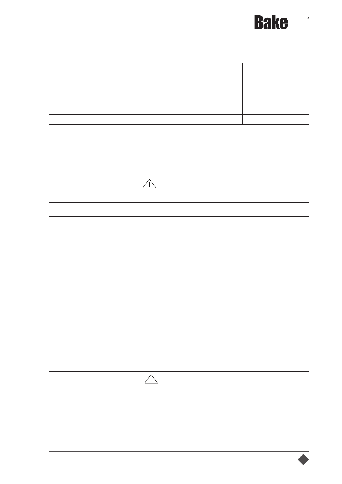
North America, by referring to the National Fuel Gas Code, Appendix C, Table C-4 (for
natural gas) and Table C-16 (for propane). The gas line needs to be large enough to
supply the necessary amount of fuel to all appliances without losing pressure to any
appliance.
Max
MaxMax
R
WARNING
Never supply the appliance with a gas other than the one that is indicated on the data
plate. Using the incorrect gas type will cause improper operation and could result in
serious injury or death. If you need to convert the appliance to another type of fuel,
contact the dealer your purchased it from.
Never use an adaptor to make a smaller gas supply line fit the cooker connection.
This may not allow the correct amount of gas flow for optimum burner operation,
resulting in poor cooker performance.
NAMEPLATE
Information in the Nameplates includes the model, serial number, BTU/h input of the
burners, operating gas pressure in inches WC, and whether the appliance is orificed for
natural or propane gas. When communicating with factory about a unit or requesting
special parts or information, rating plate data is essential for proper identification.
THIS APPLIANCE MUST BE INSTALLED UNDER A VENTILATION HOOD.
IMPORTANT
Model
Combustible
Non-combustible
Rear
Sides
Rear
Sides
Countertop Thermostatic Gas Griddle
8"
6"
0"
0"
Countertop Manual Gas Griddle
8"
6"
0"
0"
Countertop Radiant Gas Charbroiler
8"
6"
0"
0"
Gas Hot Plate
8"
6"
0"
0"

2.5 Gas pressure regulator
The gas pressure regulator (which accompanies the equipment) is of utmost
importance for its operation and is indispensable. The pressure regulator must be
installed in the equipment supply gas line (failure to install the pressure regulator will
void the equipment warranty).
Regulators are supplied with 3/4" NPT connection ranges.
The regulator is factory set by 102 mmH2O ((4" WC) water column) gas pressure at
connector (natural gas) and gas pressure at 254 mmH2O (10" WC) connector for LPG
gas operation.
Before connecting the regulator, check the supply line pressure in the equipment.
This may not exceed the maximum pressure of 3.45 kPa (1/2 PSI). If the gas supply line
pressure is higher than indicated, use a pressure reducing regulator.
At the bottom of the regulator body there is a gas direction arrow to minimize
installation error. This arrow should point to the device’s direction of entry into the
equipment.
The blue air vent cap on the top of the regulator is part of the regulator and should not
be removed.
08
Max
MaxMax
R
2.4 Installation - gas standards and codes
In North America, gas appliances equipped with casters must be installed with
connectors that comply with the Standard for Connectors for Movable Gas Appliances,
ANSI Z21.69.CSA 6.16 Latest Edition. This connection should include a quick
disconnect device that complies with the Standard for Quick Disconnect Devices for Use
With Gas Fuel Appliances ANSI Z21.41.CSA 6.9 Latest Edition.
Installation of this appliance must be in accordance with local installation codes,
including:
1. The appliance and its individual shut off valve must be disconnected from the gas
supply piping system during any system pressure testing when this teste pressure
exceeds 1/2 PSI (3.45 kPa).
2. The appliance shall be isolated from the gas supply piping system by closing the
manual shut off valve during any pressure test of the gas supply piping system at test
pressures equal to or less than 1/2 PSI (3.45 kPa).
GAS CONNECTION
The external thread of equipment’s intake-tube is 3/4" NPT. For proper operatorion,
the gas supply line must be the same size or larger. Gas line size should not be reduced
at any point along the supply line.
MANUAL SHUT OFF VALVE
A gas pressure regulator and a shut off valve supplied by the technical shall be
installed in the gas service line before the appliance - in a physical location where it can
be reached quickly in an emergency.
FAILURE TO INSTALL THE PRESSURE REGULATOR WILL VOID YOUR
WARRANTY.
IMPORTANT

2.6 Gas conversion Instruction
After converting the equipment gas, the pressure regulator must be converted by
inverting the fitting under the regulator cover. This will require a reasonable amount of
force. Do not remove the spring.
When replacing the cover, make sure
the insert of the socket is facing
upwards in the middle of the spring.
As shown in the image on the side.
Then re-attach the pressure
regulator to the gas inlet of the
equipment and apply the "Warning"
sticker for the gas to be used on the
front of the unit for future reference.
The products are produced for the use of natural gas (NG). Then check if the gas used
in your region is compatible with the type of gas for which the equipment was
manufactured. Otherwise, the equipment must be converted to be used in propane gas
(LPG).
09
IMPORTANT
To perform gas conversion, a licensed and qualified technician is required.
Direction of the
arrow at the
bottom of the
regulator.
Air vent cap.
Visually check all inlet pipes supplied by the installer and/or blow them out using
compressed air to clean out any dirt or debris (threads or other foreign matter) before
installing a service line. These particles will clog the gas holes when gas pressure is
applied. Compounds used in appliance pipe threaded joints shall be resistant to the
action of GN and LPG gas and shall provide a gas tight seal to prevent leakage.
When installing the pressure regulator remember that it can support 1/2 PSI (3.45k
Pa).
When installing LPG, you have high source pressures ranging from 20 PSI
(127.89kPa) to 100 PSI (689.48 kPa). If the LPG tank’s high pressure gas line is directly
connected to a unit without the proper reduction regulator, it will rupture the diaphragm
in the valve, making it useless.
Any adjustment to the regulator should be done only by qualified and licensed
personnel with the appropriate calibrated test equipment.
Connections must be made by a licensed and qualified contractor.
IMPORTANT
Max
MaxMax
R

Max
MaxMax
R
10
For conversion the following guidelines should be followed:
COUNTERTOP THERMOSTATIC GAS GRIDDLE
1. Close the manual gas valve and disconnect
the equipment from the main pipeline gas,
making sure that there is no leakage. Then
remove the pressure regulator from the gas
inlet on the equipment to make work easier.
2. Remove the manual gas griddle assembly (1)
with the help of two or more people. For this,
extreme care must be taken, as physical
injuries or serious damage can occur.
3. Carefully pull the wire from the thermostat
bulb that is fixed inside a support welded on the
bottom of the plate until it is loose.
4. Remove the screws that secure the burners
(3) to the rear support and pilot burner support
(6) with the aid of the double screwdriver.
Afterwards, remove the burners from the
equipment.
5. Remove the burners
injectors (4) with a 1/2”
wrench.
6. In place of the removed
gas injectors (4), place the
new injectors that are
in cluded with th e kit
s h i p p e d w i t h t h e
equipment. But first apply
some pipe sealant to the valve thread and then screw-in the new injectors to the correct
gas type.
7. Remove the pilot burner nut (7) to change the injector orifice that is inside the nut. The
orifice for the exchange is included in the accessory kit.
8. After changing the gas injectors, reassemble your equipment. Return the burners to
their original configuration, however, now with the new injectors.
9. After repositioning the thermostat bulb inside the welded support at the bottom of the
plate, fit the plate assembly back into the equipment. Replace the panel and secure it
with the screws that were removed earlier.
The following image serves to help identify the components mentioned above.
Detail B

11
Max
MaxMax
R
COUNTERTOP MANUAL GAS GRIDDLE
For conversion the following guidelines should be followed:
1. Close the manual gas valve and
disconnect the equipment from the gas main
pipeline gas, making sure that there is no
leakage. Then remove the pressure
regulator from the gas inlet on the
equipment to make work easier.
2. Remove the manual gas griddle
assembly (1) with the help of two or more
people. For this, extreme care must be
taken, as physical injuries or serious
damage can occur.
3. Remove the screws that secure the
burners (2) to the rear support with the aid of
the double screwdriver. Afterwards, remove
the burners from the equipment.
4. Remove the injectors (3) with a 1/2”
wrench.
5. In place of the removed gas injectors (3),
place the new injectors that are included
with the kit shipped with the equipment. But
first apply some pipe sealant to the valve
thread and then screw-in the new injectors
to the correct gas type.
6. Once the gas injectors (3) are changed,
reassemble your equipment (4).
COUNTERTOP RADIANT GAS
CHARBROILER
For conversion the following guidelines
should be followed:
1. Close the manual gas valve and disconnect
the equipment from the gas main pipeline gas,
making sure that there is no leakage. Then
remove the pressure regulator from the gas inlet
on the equipment to make work easier.
2. Remove the waste drawer (1), knobs (2) from
the equipment and then remove the panel (3) by
removing the two screws located at the bottom
of the panel with the aid of a double screwdriver
and detaching the upper panel fittings on the
equipment.
3. Remove the removable grilles (9), the
deflectors (8) and the welded structure set (7).
For this, extreme care must be taken, as
physical injuries or serious damage can occur.
4. To remove the distributor tube assembly,
remove the screws that secure the distributor
tube assembly(4) to the front support with the
aid of a double screwdriver.

2.7 Gas leak check
Before lighting the equipment and putting it into operation, check all gaskets on the
gas supply line for leaks. For this, do not use any type of wrench to check for leaks, use a
sudsy soap and water solution.
Follow the steps below for the correct procedure to power on:
1. Turn pilot valves to OFF position by turning adjusting screws clockwise.
2. Turn on the manual gas valve on the inlet side of the gas supply line.
3 . Check for gas leaks at the flexible coupling or gas connector connection using a soap
solution.
4 . In moderation, spray or scrub the solution with soap on gas connections - active
bubbling indicates the location of the gas leak.
5 . If a gas leak is detected, turn off the manual gas valve at the inlet side of the gas line.
Call your certified and licensed service technician.
6. If the equipment has no gas leak, continue with the equipment operating instruction.
5. Remove the injectors (5) with a 1/2" wrench.
6. In place of the removed gas injectors (3), place the new injectors that are included with the kit
shipped with the equipment. But first apply some pipe sealant to the valve thread and then
screw-in the new injectors to the correct gas type.
7. Once the gas injectors are changed, reassemble your equipment (6).
GAS HOT PLATE
1. Close the manual gas valve and disconnect the
equipment from the gas main pipeline gas, making sure
that there is no leakage. Then remove the pressure
regulator from the gas inlet on the equipment to make work
easier.
2. Remove grills (1) and burners (2).
3. Remove the injectors (3) with a 1/2” wrench.
4. Replace the removed gas injectores (3) by the new
injectores that are included with the kit shipped with the
equipment. But first apply some pipe sealant to the valve
thread and then screw-in the new injectors to the correct
gas type.
5. Once the gas injectors (3) are changed, reassemble
your equipment (4).
Max
MaxMax
R
2.8 Foot leveling
For the proper functioning of the equipment it is ideal that the equipment is level and
perfectly fixed to the work surface. To adjust the leveling, turn item 1 (identified in the
drawing) counterclockwise to open and clockwise to close to find the best position to
operate the equipment safely.
1 - Foot regulator
12

Max
MaxMax
R
2.9 First-time use
2.10 Turning on the equipment - Product Ignition
COUNTERTOP THERMOSTATIC GAS GRIDDLE
1. Open the manual gas supply valve (which will release gas into the equipment).
2. Press lightly and rotate the handle to the pilot
position.
3. Keep it pressed and put your lighting device
(wick) passing between the pilot flame ignition hole
in the equipment panel until it comes into contact
with the pilot and ignites the flame.
4. Keep the knob pressed for 10 seconds after the
pilot flame is lit and turn the knob counterclockwise
until the temperature desired.
5. Make sure the burner is lit. If the burner does not
light, repeat the procedure.
13
Against shock damage or rocking from transportation, the sides and waste tray have
a protective PVC film. Remove any plastics, straps, or protective film from the equipment
before operating the equipment.
COUNTERTOP GRIDDLE THERMOSTATIC GAS AND COUNTERTOP GRIDDLE
MANUAL GAS
To protect the equipment against possible moisture damage between fabrication and
installation on site, the fllat-tops are coated with a layer of vegetable shortening and
brown paper.
In addition, you should remove and remove grease and brown paper, cleaning should
be performed with the aid of a sponge, mild soap and water in small amount.
After this procedure, turn the burners on and leave them on for about 15 minutes, this
will cause all flat-top grill residue to be burned and eliminated. Only then will the
equipment be ready for use.
COUNTERTOP RADIANT CHAR BROILER GAS
To protect the equipment against possible moisture damage between manufacture
and installation on site, the grills and baffle rails are coated with a layer of vegetable oil.
In addition, you should perform a cleaning with the help of a sponge, neutral soap and
water in small amounts. After this procedure, turn the burners on and leave them on for
about 15 minutes, this will cause all gas charbroiler residue to be burned and eliminated.
Only then will the equipment be ready for use.
COUNTERTOP RANGE GAS
You should perform a cleaning with the help of a sponge, neutral soap and water in
small amounts. Only then will the equipment be ready for use.

14
COUNTERTOP GRIDDLE MANUAL GAS
1. Open the manual gas supply valve (which will release gas into the equipment).
2. Put your lighting device (wick) past the ignition hole in the flame of the pilot on the
equipment panel until contact with the pilot burner and until the flame ignites, repeat this
procedure on all pilots (see following image).
Note: The ignition order does not interfere with the use of the equipment.
3. Turn the knob corresponding to the burner
you wish to operate counterclockwise (adjust
the flame through the knob).
4. Make sure the burner is lit. If the burner does
not light, repeat the procedure.
5. After lighting all burners, you can turn off the
burners and turn them back on simply by
turning the corresponding knobs.
Note: The pilot burner flame is factory set
according to the gas for which the equipment
was originally manufactured. Always check
through the hole identified on the panel as
PILOT, if the pilot burner flame is lit. If it is not,
perform the procedures described above
again.
COUNTERTOP RADIANT GAS CHARBROILER
1. Open the manual gas supply valve (which will release gas into the equipment).
2. Put your lighting device (wick) through the pilot flame ignition hole in the equipment
panel until contact with the pilot burner and until the flame ignites, repeat this procedure
on all pilots (see the following image).
3. Rotate the knob corresponding to the burner you wish to operate, rotate 90°
counterclockwise.
4. Make sure the burner is lit. If the burner does not
light, repeat the procedure.
5. After lighting all burners, you can turn off the
burners and turn them back on simply by turning
the corresponding knobs.
Note: The pilot burner flame is factory set
according to the gas for which the equipment was
originally manufactured. Always check to see if the
flame on the pilot burner can be seen through the
panel hole. If it is not lit, perform the procedures
described above again.
Max
MaxMax
R

15
Max
MaxMax
R
GAS HOT PLATE
1. Open the manual gas supply valve (which will release gas into the equipment).
2. Light the burner pilot until the flame ignites, repeat on all others. (see image below).
Note: The ignition order does not interfere with the use of the equipment.
3. Turn the knob corresponding to the burner you wish to operate counterclockwise
(adjust the flame through the knob).
4. Make sure the burner is lit. If the burner does not light, repeat the procedure.
Note: The pilot burner flame is factory set according to the gas for which the equipment
was originally manufactured. Always check that the pilot burner flame is lit. If it is not,
perform the procedures described above again.
DETAIL A
SCALE 2:5
NOTE:
If you need to adjust the pilot valves (one pilot valve corresponds to two burners) do
the following:
1-Turn the pilot adjusting screw counterclockwise, then light the pilot with the aid of the
igniter (wick) accompanying the equipment and adjust the flame to a height of
approximately 13/64" (0.5 cm);
2- Turn on the gas valve by turning the knob counterclockwise to light the main burners;
3- To shut down completely, close the gas valves by turning the knob clockwise and turn
the pilot adjusting screw clockwise to close the gas for the pilots.
Pilot screw adjustment
More gas Less gas

16
Max
MaxMax
R
03. CLEANING AND MAINTENANCE
3.1 Cleaning
ŸAfter using the equipment and with the equipment not working or hot, clean it to
remove food residue. Remove the waste drawer for debris removal and cleaning.
ŸUse a non-abrasive sponge with mild detergent and water to clean the equipment.
ŸNever use sharp or abrasive materials (with corrosive elements in the formula) on
stainless steel components, but on range and charbroiler grills it is possible. On the
Manual Griddle and Thermostatic Griddle flat-top it is recommended to use a kitchen
spatula to facilitate the cleaning of residues;
ŸKeep in mind that constant and correct cleaning is critical to the proper functioning of
the equipment.
ŸNEVER attempt to move or slide the equipment when it is hot. ALWAYS let the unit cool
down and empty the waste drawer before attempting to relocate or move the unit.
Ÿ DO NOT FLOOD A HOT GRIDDLE WITH COLD WATER. This could cause warping
and th griddle plate to crack.
ŸAfter the end of the working day, clean the Gas Range, Charbroiler and burners and
turn them on to remove moisture. On the Manual Griddle and Thermostatic Griddle clean
the equipment and grease the flat-top with vegetable oil. This practice is recommended
between one working day and another, thus avoiding its oxidation.
3.1.1 Cleaning the outside of the equipment
The equipment has stainless steel external coating and for its correct cleaning it is
necessary to follow the following guidelines:
ŸFirst, let the equipment cool. Normal daily dirt can be removed with a mild detergent or
soap solution applied with a damp cloth. Wash and dry thoroughly;
ŸTo remove deposited grease, apply a cleanser in the direction of the polished lines on
the metal. NEVER rub in a circular motion.
3.2 Maintenance
Maintenance is one of the precautions to be taken for a good equipment life. Proper
cleaning, installation, checking and equipment life all contribute to reduced
maintenance. Before any maintenance, verify that the gas connections, regulators or
check valves must be completely closed and disconnected from the equipment.
3.1.2 Cleaning the inside of the equipment
Let the inside of the equipment cool completely. Use a non-alkaline cleaning agent
following the manufacturer's recommendations;
• Do not use abrasive products;
• Rinse well with water at room temperature, clean and dry thoroughly.
IMPORTANT
Do not use toxic or high chemical cleaning materials. See all instructions given by the
cleaning equipment manufacturer.
DANGER
The maintenance of the equipment should only be performed by a technician
authorized by the manufacturer.
The operator should be familiar with how to connect and disconnect the restrictions /
removable parts. If the restriction is removed for maintenance or cleaning, it must be
reconnected before using the equipment again.

17
Max
MaxMax
R
04. TECHNICAL SPECIFICATIONS
4.1 Equipment dimensions and weight
COUNTERTOP MANUAL GAS GRIDDLE
COUNTERTOP THERMOSTATIC GAS GRIDDLE
Width
(W)
Depth
(D)
Height
(H) Fw Weight Width Depth Height Weight
BACG15-1
15"
(380 mm)
30 33/64"
(775 mm)
16 27/32"
(428 mm)
9 5/32"
(230.5 mm)
108 lb
(49 kg)
18 29/32"
(480 mm)
35 1/4"
(870 mm)
19 19/64"
(490 mm)
132 lb
(60 kg)
BACG24-2
24"
(610 mm)
30 33/64"
(775 mm)
16 27/32"
(428 mm)
18 3/32"
(459.5 mm)
163 lb
(74 kg)
27 61/64"
(710 mm)
35 1/4"
(870 mm)
19 19/64"
(490 mm)
194 lb
(88 kg)
BACG36-3
36"
(915 mm)
30 33/64"
(775 mm)
16 27/32"
(428 mm)
31 9/32"
(794.5 mm)
227 lb
(103 kg)
40 5/32"
(1020 mm)
35 1/4"
(870 mm)
19 19/64"
(490 mm)
273 lb
(124 kg)
BACG48-4
48"
(1220 mm)
30 33/64"
(775 mm)
16 27/32"
(428 mm)
43 9/32"
(1099.5 mm)
315 lb
(143 kg)
52 31/32"
(1320 mm)
35 1/4"
(870 mm)
19 19/64"
(490 mm)
353 lb
(160 kg)
BACG60-5
60"
(1525 mm)
30 33/64"
(775 mm)
16 27/32"
(428 mm)
26 5/16"
(2x668.3 mm)
360 lb
(163 kg)
64 1/16"
(1630 mm)
35 1/4"
(870 mm)
19 19/64"
(490 mm)
430 lb
(195 kg)
Model
Exterior Product Dimensions & Weight
Shipping Crate Dimensions & Weight
BACT15-1
15"
(380 mm)
30 33/64"
(775 mm)
16 27/32"
(428 mm)
9 5/64"
(230.5 mm)
112 lb
(51 kg)
18 29/32"
(480 mm)
34 1/4"
(870 mm)
19 19/64"
(490 mm)
137 lb
(62 kg)
BACT24-2
24"
(610 mm)
30 33/64"
(775 mm)
16 27/32"
(428 mm)
18 3/32"
(459.5mm)
165 lb
(75 Kg)
27 61/64"
(710mm)
34 1/4"
(870 mm)
19 19/64"
(490 mm)
196 lb
(89kg)
BACT36-3
36"
(915 mm)
30 33/64"
(775 mm)
16 27/32"
(428 mm)
31 9/32"
(794.5mm)
234 lb
(106 Kg)
40 5/32"
(1020mm)
34 1/4"
(870 mm)
19 19/64"
(490 mm)
282 lb
(128kg)
BACT48-4
48"
(1220 mm)
30 33/64"
(775 mm)
16 27/32"
(428 mm)
43 9/32"
(1099.5mm)
322 lb
(146 Kg)
52 31/32"
(1320mm)
34 1/4"
(870 mm)
19 19/64"
(490 mm)
355 lb
(161kg)
BACT60-5
60"
(1525 mm)
30 33/64"
(775 mm)
16 27/32"
(428 mm)
26 5/16"
(2x668.3mm)
368 lb
(167 Kg)
64 1/16"
(1630 mm)
34 1/4"
(870 mm)
19 19/64"
(490 mm)
439 lb
(199 kg)
Weight
Weight
Model
Exterior Product Dimensions & Weight
Shipping Crate Dimensions & Weight
Width (W)
Depth (D)
Height (H)
Fw
Width
Depth
Height

18
GAS HOT PLATE
Max
MaxMax
R
M A N IF O L D P R E S S U R E
P E R B T U P E R K c a l
B . T . u / h k c a l/ h
N A T U R A L G A S# 4 3 3 5 ,0 0 0
8 ,8 2 0 4
L . P . G A S # 5 4 3 5 ,0 0 0
8 ,8 2 0 1 0
N A T U R A L G A S# 4 3 7 0 ,0 0 0
1 7 ,6 4 0 4
L . P . G A S # 5 4 7 0 ,0 0 0
1 7 ,6 4 0 1 0
N A T U R A L G A S# 4 3 1 0 5 , 0 0 0
2 6 ,4 6 0 4
L . P . G A S # 5 4 1 0 5 , 0 0 0
2 6 ,4 6 0 1 0
N A T U R A L G A S# 4 3 1 4 0 , 0 0 0
3 5 ,2 8 0 4
L . P . G A S # 5 4 1 4 0 , 0 0 0
3 5 ,2 8 0 1 0
N A T U R A L G A S# 4 3 1 7 5 , 0 0 0
4 4 ,1 0 0 4
L . P . G A S # 5 4 1 7 5 , 0 0 0
4 4 ,1 0 0 1 0
N A T U R A L G A S# 4 4 3 0 ,0 0 0
7 ,5 6 0 4
L . P . G A S # 5 4 3 0 ,0 0 0
7 ,5 6 0 1 0
N A T U R A L G A S# 4 4 6 0 ,0 0 0
1 5 ,1 2 1 4
L . P . G A S # 5 4 6 0 ,0 0 0
1 5 ,1 2 1 1 0
N A T U R A L G A S# 4 4 9 0 ,0 0 0
2 2 ,6 8 0 4
L . P . G A S # 5 4 9 0 ,0 0 0
2 2 ,6 8 0 1 0
N A T U R A L G A S# 4 4 1 2 0 , 0 0 0
3 0 ,2 4 0 4
L . P . G A S # 5 4 1 2 0 , 0 0 0
3 0 ,2 4 0 1 0
N A T U R A L G A S# 4 4 1 5 0 , 0 0 0
3 7 ,8 0 0 4
L . P . G A S # 5 4 1 5 0 , 0 0 0
3 7 ,8 0 0 1 0
N A T U R A L G A S# 4 0 3 0 ,0 0 0
7 ,5 6 0 4
L . P . G A S # 5 2 3 0 ,0 0 0
7 ,5 6 0 1 0
N A T U R A L G A S# 4 0 6 0 ,0 0 0
1 5 ,1 2 0 4
L . P . G A S # 5 2 6 0 ,0 0 0
1 5 ,1 2 0 1 0
N A T U R A L G A S# 4 0 9 0 ,0 0 0
2 2 ,6 8 0 4
L . P . G A S # 5 2 9 0 ,0 0 0
2 2 ,6 8 0 1 0
N A T U R A L G A S# 4 0 1 2 0 , 0 0 0
3 0 ,2 4 0 4
L . P . G A S # 5 2 1 2 0 , 0 0 0
3 0 ,2 4 0 1 0
N A T U R A L G A S# 4 0 5 6 ,0 0 0 1 4 ,1 2 0
4
L . P . G A S # 5 3 5 6 ,0 0 0 1 4 ,1 2 0
1 0
N A T U R A L G A S# 4 0 1 1 2 , 0 0 0 2 8 ,2 4 0
4
L . P . G A S # 5 3 1 1 2 , 0 0 0 2 8 ,2 4 0
1 0
N A T U R A L G A S# 4 0 1 6 8 , 0 0 0 4 2 ,3 6 0
4
L . P . G A S # 5 3 1 6 8 , 0 0 0 4 2 ,3 6 0
1 0
N A T U R A L G A S# 4 0 2 2 4 , 0 0 0 5 6 ,4 8 0
4
L . P . G A S # 5 3 2 2 4 , 0 0 0 5 6 ,4 8 0
1 0
N A T U R A L G A S# 4 0 2 8 0 , 0 0 0 7 0 ,6 0 0
4
L . P . G A S # 5 3 2 8 0 , 0 0 0 7 0 ,6 0 0
1 0
G A S S U P P L Y
P H P 1 2 G - C T
2
P H P 2 4 G - C T
4
P C B 2 4 G - C T
2
P C B 3 6 G - C T
3
P C B 4 8 G - C T
4
P G M 1 5 G - C T
P G T 6 0 G - C T
5
1
T U B E P R E S S U R E
( in . W . C )
C o u n t e r to p M a n u a l G a s
G r id d l e ( P r im e S e r i e s )
C o u n t e r to p T h e r m o s t a t i c
G a s G r id d l e ( P r im e S e r ie s )
P G T 1 5 G - C T
1
P G T 2 4 G - C T
2
P R O D U C T
M O D E L
B U R N E R S
G A S T Y P E
N O Z Z L E
P G T 3 6 G - C T
3
P G M 6 0 G - C T
5
P G T 4 8 G - C T
4
C o u n t e r to p R a d ia n t G a s
C h a r b r o il e r ( P r im e S e r ie s )
P C B 1 5 G - C T
1
P G M 2 4 G - C T
2
P G M 4 8 G - C T
4
P G M 3 6 G - C T
3
G a s H o t P l a t e ( P r im e S e r ie s )
P H P 4 8 G - C T
P H P 6 0 G - C T
8
1 0
P H P 3 6 G - C T
6
COUNTERTOP RADIANT GAS CHARBROILER
Width
(W)
Depth
(D)
Height
(H) Fw Weight Width Depth Height Weight
BACGG18-2
18"
(457 mm)
30 33/64"
(775 mm)
16 27/32"
(428 mm)
9 5/64"
(230.5 mm)
88 lb
(40 kg)
20 7/8"
(530 mm)
34 1/4"
(870 mm)
19 19/64"
(490 mm)
132 lb
(60 kg)
BACGG24-2
24"
(610 mm)
30 33/64"
(775 mm)
16 27/32"
(428 mm)
18 3/32"
(459.5mm)
152 lb
(69 kg)
28 61/64"
(710 mm)
34 1/4"
(870 mm)
19 19/64"
(490 mm)
183 lb
(83 kg)
BACGG36-3
36"
(915 mm)
30 33/64"
(775 mm)
16 27/32"
(428 mm)
31 9/32"
(794.5mm)
212 lb
(96 kg)
40 5/32"
(1020 mm)
34 1/4"
(870 mm)
19 19/64"
(490 mm)
258 lb
(117 kg)
BACGG48-4
48"
(1220 mm)
30 33/64"
(775 mm)
16 27/32"
(428 mm)
43 9/32"
(1099.5mm)
280 lb
(127 kg)
52 31/32"
(1320 mm)
34 1/4"
(870 mm)
19 19/64"
(490 mm)
329 lb
(149kg)
Model
Exterior Product Dimensions & Weight
Shipping Crate Dimensions & Weight
Width
(W)
Depth
(D)
Height
(H) Fw Weight Width Depth Height Weight
BAFA2M-12
12"
(305 mm)
30 33/64"
(775 mm)
16 27/32"
(428 mm)
9 5/64"
(230.5 mm)
70 lb
(32 kg)
16 9/64"
(410 mm)
34 1/4"
(870 mm)
18 1/2"
(490 mm)
93 lb
(42 kg)
BAFA4M-24
24"
(610 mm)
30 33/64"
(775 mm)
16 27/32"
(428 mm)
9 5/64"
(230.5 mm)
121 lb
(55 kg)
28 1/16"
(715 mm)
34 1/4"
(870 mm)
18 1/2"
(490 mm)
154 lb
(70 kg)
BAFA6M-36
36"
(915 mm)
30 33/64"
(775 mm)
16 27/32"
(428 mm)
9 5/64"
(230.5 mm)
176 lb
(80 kg)
28 1/16"
(715 mm)
34 1/4"
(870 mm)
18 1/2"
(490 mm)
218 lb
(99 kg)
Model
Exterior Product Dimensions & Weight
Shipping Crate Dimensions & Weight

19
4.2 Technical data
Max
MaxMax
R
M A N IF O L D P R E S S U R E
P E R B T U P E R K c a l
B . T . u / h k c a l/ h
N A T U R A L G A S# 4 3 3 5 ,0 0 0
8 ,8 2 0 4
L . P . G A S # 5 4 3 5 ,0 0 0
8 ,8 2 0 1 0
N A T U R A L G A S# 4 3 7 0 ,0 0 0
1 7 ,6 4 0 4
L . P . G A S # 5 4 7 0 ,0 0 0
1 7 ,6 4 0 1 0
N A T U R A L G A S# 4 3 1 0 5 , 0 0 0
2 6 ,4 6 0 4
L . P . G A S # 5 4 1 0 5 , 0 0 0
2 6 ,4 6 0 1 0
N A T U R A L G A S# 4 3 1 4 0 , 0 0 0
3 5 ,2 8 0 4
L . P . G A S # 5 4 1 4 0 , 0 0 0
3 5 ,2 8 0 1 0
N A T U R A L G A S# 4 3 1 7 5 , 0 0 0
4 4 ,1 0 0 4
L . P . G A S # 5 4 1 7 5 , 0 0 0
4 4 ,1 0 0 1 0
N A T U R A L G A S# 4 4 3 0 ,0 0 0
7 ,5 6 0 4
L . P . G A S # 5 4 3 0 ,0 0 0
7 ,5 6 0 1 0
N A T U R A L G A S# 4 4 6 0 ,0 0 0
1 5 ,1 2 1 4
L . P . G A S # 5 4 6 0 ,0 0 0
1 5 ,1 2 1 1 0
N A T U R A L G A S# 4 4 9 0 ,0 0 0
2 2 ,6 8 0 4
L . P . G A S # 5 4 9 0 ,0 0 0
2 2 ,6 8 0 1 0
N A T U R A L G A S# 4 4 1 2 0 , 0 0 0
3 0 ,2 4 0 4
L . P . G A S # 5 4 1 2 0 , 0 0 0
3 0 ,2 4 0 1 0
N A T U R A L G A S# 4 4 1 5 0 , 0 0 0
3 7 ,8 0 0 4
L . P . G A S # 5 4 1 5 0 , 0 0 0
3 7 ,8 0 0 1 0
N A T U R A L G A S# 4 0 3 0 ,0 0 0
7 ,5 6 0 4
L . P . G A S # 5 2 3 0 ,0 0 0
7 ,5 6 0 1 0
N A T U R A L G A S# 4 0 6 0 ,0 0 0
1 5 ,1 2 0 4
L . P . G A S # 5 2 6 0 ,0 0 0
1 5 ,1 2 0 1 0
N A T U R A L G A S# 4 0 9 0 ,0 0 0
2 2 ,6 8 0 4
L . P . G A S # 5 2 9 0 ,0 0 0
2 2 ,6 8 0 1 0
N A T U R A L G A S# 4 0 1 2 0 , 0 0 0
3 0 ,2 4 0 4
L . P . G A S # 5 2 1 2 0 , 0 0 0
3 0 ,2 4 0 1 0
N A T U R A L G A S# 4 0 5 6 ,0 0 0 1 4 ,1 2 0
4
L . P . G A S # 5 3 5 6 ,0 0 0 1 4 ,1 2 0
1 0
N A T U R A L G A S# 4 0 1 1 2 , 0 0 0 2 8 ,2 4 0
4
L . P . G A S # 5 3 1 1 2 , 0 0 0 2 8 ,2 4 0
1 0
N A T U R A L G A S# 4 0 1 6 8 , 0 0 0 4 2 ,3 6 0
4
L . P . G A S # 5 3 1 6 8 , 0 0 0 4 2 ,3 6 0
1 0
N A T U R A L G A S# 4 0 2 2 4 , 0 0 0 5 6 ,4 8 0
4
L . P . G A S # 5 3 2 2 4 , 0 0 0 5 6 ,4 8 0
1 0
N A T U R A L G A S# 4 0 2 8 0 , 0 0 0 7 0 ,6 0 0
4
L . P . G A S # 5 3 2 8 0 , 0 0 0 7 0 ,6 0 0
1 0
G A S S U P P L Y
P H P 1 2 G - C T
2
P H P 2 4 G - C T
4
P C B 2 4 G - C T
2
P C B 3 6 G - C T
3
P C B 4 8 G - C T
4
P G M 1 5 G - C T
P G T 6 0 G - C T
5
1
T U B E P R E S S U R E
( in . W . C )
C o u n t e r to p M a n u a l G a s
G r id d l e ( P r im e S e r i e s )
C o u n t e r to p T h e r m o s t a t i c
G a s G r id d l e ( P r im e S e r ie s )
P G T 1 5 G - C T
1
P G T 2 4 G - C T
2
P R O D U C T
M O D E L
B U R N E R S
G A S T Y P E
N O Z Z L E
P G T 3 6 G - C T
3
P G M 6 0 G - C T
5
P G T 4 8 G - C T
4
C o u n t e r to p R a d ia n t G a s
C h a r b r o il e r ( P r im e S e r ie s )
P C B 1 5 G - C T
1
P G M 2 4 G - C T
2
P G M 4 8 G - C T
4
P G M 3 6 G - C T
3
G a s H o t P l a t e ( P r im e S e r ie s )
P H P 4 8 G - C T
P H P 6 0 G - C T
8
1 0
P H P 3 6 G - C T
6
GAS SUPPLY
MANIFOLD
PRODUCT
MODEL
BURNERS
GAS TYPE
NOZZLE
PER BTU
PER Kcal
TUBE PRESSURE
(in. W.C)
BTU/h
kcal/h
Countertop
Thermostatic Gas
Griddle
BACT15-1
1
NATURAL GAS
#43
35,000
8,820
4
L.P GAS
#54
35,000
8,820
10
BACT24-2
2
NATURAL GAS
#43
70,000
17,640
4
L.P GAS
#54
70,000
17,640
10
BACT36-3
3
NATURAL GAS
#43
105,000
26,460
4
L.P GAS
#54
105,000
26,460
10
BACT48-4
4
NATURAL GAS
#43
140,000
35,280
4
L.P GAS
#54
140,000
35,280
10
BACT60-6
5
NATURAL GAS
#43
175,000
44,100
4
L.P GAS
#54
175,000
44,100
10
Countertop Manual
Gas Griddle
BACG15-1
1
NATURAL GAS
#44
30,000
7,560
4
L.P GAS
#54
30,000
7,560
10
BACG24-2
2
NATURAL GAS
#44
60,000
15,120
4
L.P GAS
#54
60,000
15,120
10
BACG36-3
3
NATURAL GAS
#44
90,000
22,680
4
L.P GAS
#54
90,000
22,680
10
BACG48-4
4
NATURAL GAS
#44
120,000
30,240
4
L.P GAS
#54
120,000
30,240
10
BACG60-5
5
NATURAL GAS
#44
150,000
37,800
4
L.P GAS
#54
150,000
37,800
10
Countertop Radiant
Gas Charbroiler
BACGG18-2
2
NATURAL GAS
#40
30,000
7,560
4
L.P GAS
#52
30,000
7,560
10
BACGG24-2
2
NATURAL GAS
#40
60,000
15,120
4
L.P GAS
#52
60,000
15,120
10
BACGG36-3
3
NATURAL GAS
#40
90,000
22,680
4
L.P GAS
#52
90,000
22,680
10
BACGG48-4
4
NATURAL GAS
#40
120,000
30,240
4
L.P GAS
#52
120,000
30,240
10
Gas Hot Plate
BAFA2M-12
2
NATURAL GAS
#40
50,000
12,600
4
L.P GAS
#53
50,000
12,600
10
BAFA4M-24
4
NATURAL GAS
#40
100,000
25,200
4
L.P GAS
#53
100,000
25,200
10
BAFA6M-36
6
NATURAL GAS
#40
150,000
37,800
4
L.P GAS
#53
150,000
37,800
10

20
Max
MaxMax
R
05. MAIN COMPONENTS
COUNTERTOP MANUAL GAS GRIDDLE
# SIZE CODE DESCRIPTION PGM15G-CT PGM24G-CT PGM36G-CT PGM48G-CT PGM60G-CT
15" 8.01.53.00006700
24" 8.01.52.00072100
36" 8.01.52.00074300
48" 8.01.52.00074700
60" 8.01.53.00008900
2 15" - 24" - 36" - 48" - 60" 8.01.53.00009500 BURNER ASSEMBLY 1 2 3 4 5
3 15" - 24" - 36" - 48" - 60" 8.01.52.00000785 BURNER DEFLECTOR 1 2 3 4 5
4 15" - 24" - 36" - 48" - 60" 8.01.53.00000042 GAS TUBE BACK BRACKET 1 1 1 1 1
15" 8.01.53.00000073
24" 8.01.52.00000786
36" 8.01.52.00000835
48" 8.01.52.00000547
60" 8.01.53.00000120
15" 8.01.53.00000074
24" 8.01.52.00000787
36" 8.01.52.00000836
48" 8.01.52.00000848
60" 8.01.53.00000121
7 15" - 24" - 36" - 48" - 60" 8.01.53.00000151 TOP BURNER DEFLECTOR 1 2 3 4 5
15" 8.01.53.00006600
24" 8.01.52.00072400
36" 8.01.52.00074400
48" 8.01.52.00074800
60" 8.01.53.00008800
9 15" - 24" - 36" - 48" - 60" 8.01.52.00000788 EXTERNAL SIDE PANEL 2 2 2 2 2
10 15" - 24" - 36" - 48" - 60" 8.01.52.00002300 SINGLE PILOT TUBE 1 0 1 0 1
11 15" - 24" - 36" - 48" - 60" 8.01.52.00072500 DOUBLE PILOT TUBE 0 1 1 2 2
12 15" - 24" - 36" - 48" - 60" 8.09.03.00000400 LEG ASSEMBLY 4 4 4 4 6
13 15" - 24" - 36" - 48" - 60" 8.01.53.00001900 KNOB ASSEMBLY 1 2 3 4 5
15" 8.01.53.00000075
24" 8.01.52.00000781
36" 8.01.53.00000080
48" 8.01.53.00000094
60"
8.01.52.00000781
15" 8.01.53.00000109
24" 8.01.52.00000780
36" 8.01.52.00000841
48" 8.01.52.00000853
60" 8.01.53.00000126
15" 8.01.53.00007100
24" 8.01.53.00004500
36" 8.01.52.00074500
48" 8.01.52.00074900
60" 8.01.53.00009000
1
1
1
8
INTERNAL FRAME ASSEMBLY
1
1
1
1
1
15
16
GAS DISTRIBUTION TUBE ASSEMBLY
1
1
1
2
FRONT PANEL
1
1
1
1
1
14
GREASE TRAP
1
1
1
1
1
6
INTERNAL BACK PANEL
1
1
1
1
1
5
EXTERNAL BACK PANEL
1
1
1
MAIN COMPONENTS OF COUNTERTOP MANUAL GAS GRIDDLE
QUANTITY
GRIDDLE PLATE ASSEMBLY
1
1
1
1
1
1
# SIZE CODE DESCRIPTION BACG15-1 BACG24-2 BACG36-3 BACG48-4 BACG60-5
15" 8.01.53.00006700
24" 8.01.52.00072100
36" 8.01.52.00074300
48" 8.01.52.00074700
60" 8.01.53.00008900
2 15" - 24" - 36" - 48" - 60" 8.01.53.00009500 BURNER ASSEMBLY 1 2 3 4 5
3 15" - 24" - 36" - 48" - 60" 8.01.52.00000785 BURNER DEFLECTOR 1 2 3 4 5
4 15" - 24" - 36" - 48" - 60" 8.01.53.00000042 GAS TUBE BACK BRACKET 1 1 1 1 1
15" 8.01.53.00000073
24" 8.01.52.00000786
36" 8.01.52.00000835
48" 8.01.52.00000547
60" 8.01.53.00000120
15" 8.01.53.00000074
24" 8.01.52.00000787
36" 8.01.52.00000836
48" 8.01.52.00000848
60" 8.01.53.00000121
7 15" - 24" - 36" - 48" - 60" 8.01.53.00000151 TOP BURNER DEFLECTOR 1 2 3 4 5
15" 8.01.53.00006600
24" 8.01.52.00072400
36" 8.01.52.00074400
48" 8.01.52.00074800
60" 8.01.53.00008800
9 15" - 24" - 36" - 48" - 60" 8.01.52.00000788 EXTERNAL SIDE PANEL 2 2 2 2 2
10 15" - 24" - 36" - 48" - 60" 8.01.52.00002300 SINGLE PILOT TUBE 1 0 1 0 1
11 15" - 24" - 36" - 48" - 60" 8.01.52.00072500 DOUBLE PILOT TUBE 0 1 1 2 2
12 15" - 24" - 36" - 48" - 60" 8.09.03.00000400 LEG ASSEMBLY 4 4 4 4 6
13 15" - 24" - 36" - 48" - 60" 8.01.53.00001900 KNOB ASSEMBLY 1 2 3 4 5
15" 8.01.53.00000075
24" 8.01.52.00000781
36" 8.01.53.00000080
48" 8.01.53.00000094
60"
8.01.52.00000781
15" 8.01.53.00000109
24" 8.01.52.00000780
36" 8.01.52.00000841
48" 8.01.52.00000853
60" 8.01.53.00000126
15" 8.01.53.00007100
24" 8.01.53.00004500
36" 8.01.52.00074500
48" 8.01.52.00074900
60" 8.01.53.00009000
MAIN COMPONENTS OF COUNTERTOP MANUAL GAS GRIDDLE
QUANTITY
GRIDDLE PLATE ASSEMBLY
1
1
1
1
1
1
1
1
6
INTERNAL BACK PANEL
1
1
1
1
1
5
EXTERNAL BACK PANEL
1
1
1
14
GREASE TRAP
1
1
1
2
FRONT PANEL
1
1
1
1
1
1
1
1
8
INTERNAL FRAME ASSEMBLY
1
1
1
1
1
15
16
GAS DISTRIBUTION TUBE ASSEMBLY
1
1
1
This manual suits for next models
17
Table of contents